QOQBLED112Bluetooth USB Dongle
Silicon Laboratories Finland Oy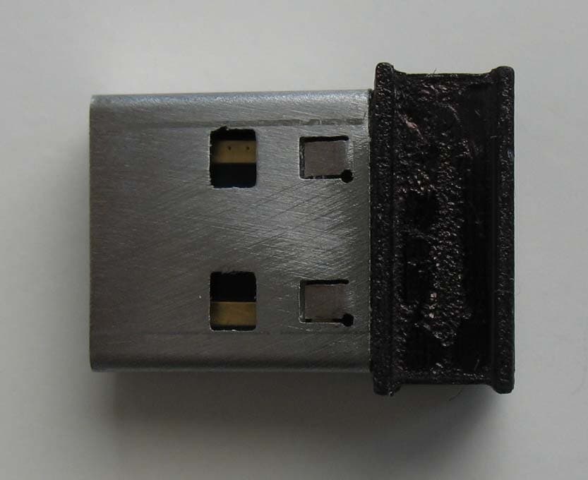
Click to zoom
Application Details
- Equipment Class
- DTS - Digital Transmission System
- Date of Grant
- Sep 08, 2011
- Application Purpose
- Original Equipment
- Date of Application
- Sep 08, 2011
- Equipment Note
- Bluetooth USB Dongle
- Frequency Range
- 2402.00000000 - 2480.00000000
- Country
- Finland
Documents & Files
Document Text
Text extracted from the exhibit documents filed with the FCC. Open a document above to read the original.
Users Manual
BLED112 USER GUIDE Friday, 19 August 2011 Version 1.0 Bluegiga Technologies Oy Copyright © 2000-2011 Bluegiga Technologies All rights reserved. Bluegiga Technologies assumes no responsibility for any errors which may appear in this manual. Furthermore, Bluegiga Technologies reserves the right to alter the hardware, software, and/or specifications detailed here at any time without notice and does not make any commitment to update the information contained here. Bluegiga’s products are not authorized for use as critical components in life support devices or systems. The WRAP is a registered trademark of Bluegiga Technologies The Bluetooth trademark is owned by the Bluetooth SIG Inc., USA and is licensed to Bluegiga Technologies. All other trademarks listed herein are owned by their respective owners. Bluegiga Technologies Oy VERSION HISTORY Version Comment 1.0 Bluegiga Technologies Oy TABLE OF CONTENTS 1 Installation .................................................................................................................................................... 5 2 General Information and Specifications ....................................................................................................... 6 3 Certifications ................................................................................................................................................. 7 4 Contact Information ...................................................................................................................................... 9 Bluegiga Technologies Oy Preliminary – information subject to change Page 5 of 9 1 Installation Please refer to BLEGUI User Guide. BLEGUI User Guide can be down loaded from (http://www.bluegiga.com/support ). Bluegiga Technologies Oy Preliminary – information subject to change Page 6 of 9 2 General Information and Specifications BLED112, Bluetooth low energy USB Dongle is a single mode USB device enabling Bluetooth low energy connectivity for PC’s and other devices having a USB port. BLED112 Bluetooth Dongle integrates all Bluetooth 4.0 single mode features. The USB dongle can simulate standard USB device, virtual COM port or USB HID device. The HID can be used for accessories like keyboards and mice, because no driver is needed. The COM port emulation enables simple host application development using a simple application programming interface. The BLED112 can be used for Bluetooth low energy development. With two BLED112 dongles you can quickly prototype new low energy application profiles by utilizing Bluegiga BG Profile Toolkit TM and also automate inmodule software functions with BGScript TM . Key Features Bluetooth v.4.0, single mode compliant Supports master and slave modes 4+ simultaneous connection is master mode Integrated Bluetooth low energy stack GAP, GATT, L2CAP, SMP Bluetooth low energy profiles Radio performance TX power: +4 dBm to -23dBm RX sensitivity: -87dBm to -93dBm USB, USB HID and virtual COM port emulation Bluetooth Low Energy Features Bluetooth 4.0 single mode compliant radio Master and slave mode support L2CAP, GAP, ATT and GATT support Security manager Advertizing, broadcasting, connections Built-in profiles Hardware Features Bluetooth low energy radio Built-in antenna 8051 microcontroller 8 kB RAM 128kB flash USB 2.0 device Programmable led 3 x timer Integrated temperature sensor Bluegiga Technologies Oy Preliminary – information subject to change Page 7 of 9 3 Certifications 3.1 Bluetooth BLED112 Bluetooth low energy module is Bluetooth qualified and listed as an End Product. 3.2 FCC and IC This equipment has been tested and found to comply with the limits for a Class B digital device, pursuant to Part 15 of the FCC Rules. These limits are designed to provide reasonable protection against harmful interference in a residential installation. This equipment generates, uses and can radiate radio frequency energy and, if not installed and used in accordance with the instructions, may cause harmful interference to radio communications. However, there is no guarantee that interference will not occur in a particular installation. If this equipment does cause harmful interference to radio or television reception, which can be determined by turning the equipment off and on, the user is encouraged to try to correct the interference by one of the following measures: Reorient or relocate the receiving antenna Increase the separation between the equipment and receiver Connect the equipment into an outlet on a circuit different from that to which the receiver is connected Consult the dealer or an experienced radio/TV technician for help FCC Caution : To assure continued compliance, any changes or modifications not expressly approved by the party responsible for compliance could void the user's authority to operate this equipment. (Example - use only shielded interface cables when connecting to computer or peripheral devices). FCC Radiation Exposure Statement This equipment complies with FCC RF radiation exposure limits set forth for an uncontrolled environment. This device complies with Part 15 of the FCC Rules. Operation is subject to the following two conditions: (1) This device may not cause harmful interference, and (2) This device must accept any interference received, including interference that may cause undesired operation. IC Statements: This device complies with Industry Canada licence-exempt RSS standard(s). Operation is subject to the following two conditions: (1) this device may not cause interference, and (2) this device must accept any interference, including interference that may cause undesired operation of the device. Under Industry Canada regulations, this radio transmitter may only operate using an antenna of a type and maximum (or lesser) gain approved for the transmitter by Industry Canada. To reduce potential radio Bluegiga Technologies Oy Preliminary – information subject t…
Text truncated - open the document above for the full version.
External Photos
Bluegiga Technologies Sinikalliontie 5A, P.O. Box 120 02630 Espoo FINLAND Tel +358 9 435 5060 | Fax +358 9 435 50660 Co ID 0934238-1, VAT registered, domicile: Espoo www.bluegiga.com | [email protected] Picture 1: External top view Picture 2: External side view
ID Label/Location Info
Bluegiga Technologies Sinikalliontie 5A, P.O. Box 120 02630 Espoo FINLAND Tel +358 9 435 5060 | Fax +358 9 435 50660 Co ID 0934238-1, VAT registered, domicile: Espoo www.bluegiga.com | [email protected] FCC ID Label for BLED112 FCC ID: QOQBLED112 IC: 5123A‐BGTBLED112 RID number TBD Model: BLED112
Internal Photos
Bluegiga Technologies Sinikalliontie 5A, P.O. Box 120 02630 Espoo FINLAND Tel +358 9 435 5060 | Fax +358 9 435 50660 Co ID 0934238-1, VAT registered, domicile: Espoo www.bluegiga.com | [email protected] Picture 3: Internal top view Picture 4: Internal bottom view
Test Report
Reference number: 264152-10 Page 1 of 58 These test results are valid for the tested unit only. This report shall not be reproduced, except in full, without a written permission of SGS Fimko. Test Report INTENTIONAL RADIATOR TESTS ACCORDING TO FCC PART 15 C and INDUSTRY CANADA REQUIREMENTS Equipment Under Test: Bluetooth dongle Model: BLED112 Type: - Manufacturer: Bluegiga Oy Sinikalliontie 5 A FI-02630 ESPOO Finland Customer: Bluegiga Oy Sinikalliontie 5 A FI-02630 ESPOO Finland FCC Rule Part: 15.247: 2010 IC Rule Part RSS-210, Issue 8, 2010 RSS-GEN Issue 3, 2010 Date: 09.09.2011 Date: 09.09.2011 Issued by: Checked by: Jari Merikari Ari Honkala Technical Manager Product Line Manager Reference number: 264152-10 Page 2 of 58 Table of Contents PRODUCT DESCRIPTION 3 Equipment Under Test (EUT) 3 Description of the EUT 3 Ratings and declarations 3 Power Supply 3 Mechanical Size of the EUT 4 Peripherals 4 Samples 4 GENERAL REMARKS 5 Disclaimer 5 SUMMARY OF TESTING 6 EUT Test Conditions During Testing 6 TEST RESULTS 7 Maximum Peak Conducted Output Power 7 Transmitter Radiated Emissions 30 – 1000 MHz 11 Transmitter Radiated Emissions 1 000 – 26 500 MHz 15 Transmitter Band Edge Measurement and Conducted Spurious Emissions 26 6 dB Bandwidth of the Channel 41 Power Spectral Density 45 99% Occupied Bandwidth 49 Receiver Radiated Emissions 30 – 26 500 MHz 53 Conducted emissions 56 LIST OF TEST EQUIPMENTS 58 Reference number: 264152-10 Page 3 of 58 Product Description PRODUCT DESCRIPTION Equipment Under Test (EUT) Bluetooth module Model: BLED112 Type: - Serial no: - HW version: SW version: 1.0 FCC ID number: QOQBLED112 Industry Canada number: 5123A-BGTBLED112 Description of the EUT The EUT is a Bluetooth low energy dongle designed to be used in the USB port of the PC. Classification of the device Fixed device Mobile Device (Human body distance > 20cm) Portable Device (Human body distance < 20cm) Modifications Incorporated in the EUT No modifications were applied to the EUT during testing Ratings and declarations Operating Frequency Range (OFR): 2402 – 2480 MHz Channels: 40 Channel separation: 2 MHz Channel bandwidth: 666.7 kHz Conducted power: -1.7 dBm Transmission technique: Digital Transmission Modulation: GFSK Antenna connector type Internal antenna Antenna gain: 0 dBi Power Supply Powered from the USB port of the computer Tested by using the IBM 30 laptop Reference number: 264152-10 Page 4 of 58 Product Description Mechanical Size of the EUT Height: 7.0 mm Width:13.5 mm Depth: 18.0 mm Peripherals Peripheral Laptop IBM 30 Samples All tests were performed with two samples. Sample A: equipped with 50Ω connector Sample B: normal construction. All conducted measurements were made to sample A, and radiated measurements to sample B. No modifications were done during the tests. Reference number: 264152-10 Page 5 of 58 General remarks GENERAL REMARKS Disclaimer This test report is issued under SGS Fimko general terms of delivery (available on request and accessible at www.fi.sgs.com). Attention is drawn to the limitations of liability, indemnification and jurisdictional issues defined therein. Unless otherwise stated: (a) the results shown in this document refer only to the sample(s) tested and (b) such sample(s) are retained for three months. This document cannot be reproduced except in full, without prior approval of SGS Fimko. Any unauthorized alteration, forgery or falsification of the content or appearance of this report is unlawful and offenders may be prosecuted to the fullest extent of the law Reference number: 264152-10 Page 6 of 58 Summary of Testing SUMMARY OF TESTING Test Specification Description of Test Result §15.247(b)(3) / RSS-210 A8.4 Maximum Peak Conducted Output Power PASS §15.247(a)(2) / RSS-210 A8.2 6 dB Bandwidth PASS §15.247(e) / RSS-210 A8.2 Power Spectral Density PASS RSS-GEN 4.6.1 99% Occupied Bandwidth PASS §15.247(d) / RSS-210 A8.5 100 kHz Bandwidth of Frequency Band Edges and Conducted Spurious Emissions PASS §15.209(a), §15.247(d) / RSS-210 A8.5 Radiated Emissions Within The Restricted Bands PASS §15.109 / RSS-GEN 7.2.3.2 Unintentional Radiated Emissions PASS §15.207 / RSS-GEN 7.2.2 Conducted emissions PASS EUT Test Conditions During Testing The EUT was in continuous transmit mode during all the tests. The hopping was stopped and the EUT was configured into the wanted channel. Normal modulation and duty cycle was applied in all the tests. Following channels were used during the tests when the hopping was stopped: Channel LOW (CH 0) = 2402 MHz Channel MID (CH 20) = 2440 MHz Channel HIGH (CH 39) = 2480 MHz Test Facility Testing Location / address: FCC registration number: 90598 SGS Fimko Ltd Särkiniementie 3 FI-00210, HELSINKI FINLAND Testing Location / address: FCC registration number: 178986 Industry Canada registration number: 8708A-2 SGS Fimko Ltd Karakaarenkuja 4 FI-02610, ESPOO FINLAND Reference number: 264152-10 Page 7 of 58 Conducted Output Power Test TEST RESULTS Maximum Peak Conducted Output Power Standard: ANSI C63.10 (2009) Tested by: JJM Date: 24.5.2011 Humidity: 38 % Temperature: 21 C Measurement uncertainty 2,87dB Level of confidence 95 % (k = 2) FCC Rule: 15.247(b) (1) For frequency hopping systems operating in the 2400-2483.5 MHz, employing less that 75 channels limit is 0.125 Watt. Maximum Conducted Output Power is defined as the total transmit power delivered to all antennas and antenna elements averaged across all symbols in the signalling alphabet when the transmitter is operating at its maximum power control level. Power must be summed across all antennas and antenna elements. The average must not include any time intervals during which the transmitter is off or is transmitting at a reduced power level. If multiple modes of operation are possible (e.g., alternative modulation methods), the maximum conducted output power is the highest total transmit power occurring in any mode. Results: Channel Conducted Power [dBm] Limit [dBm] Margin [dBm] Result Low -2.0…
Text truncated - open the document above for the full version.
Test Setup Photos
1 (3) 18.8.2011 Test setup photographs. Bluegiga Oy Dongle connected to USB port. Conducted emissions test setup. 2 (3) 18.8.2011 Conducted emissions test setup. 3 (3) 18.8.2011 Radiated emission test setup. EUT connected to USB port during the radiated emission test.
Contact Information
Applicant
Enrico Taddeo(Senior Applications and Certifications Engineer)
Test Firm
SGS Fimko OyJanne Nyman
Technical Specifications
| # | Rule Parts | Frequency Range | Power Output |
|---|---|---|---|
| 1 | 15C | 2.40 GHz - 2.48 GHz | 680.00 µW |
Other Applications from Silicon Laboratories Finland Oy
QOQ-GM270S
Dec 15, 2025Bluetooth Low Energy (LE), and 802.15.4 Wireless Radio Module
Equipment Class
DTS - Digital Transmission System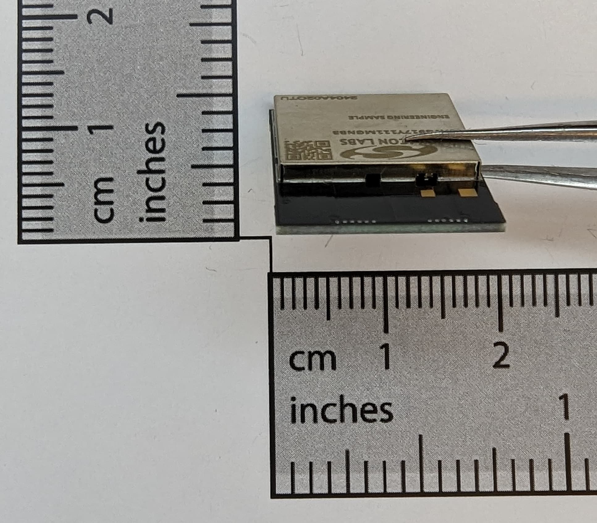
QOQ-917AC
Sep 23, 2024Bluetooth Low Energy (LE), and Wi-Fi 802.11b/g/n/ax wireless radio module
Equipment Class
DTS - Digital Transmission System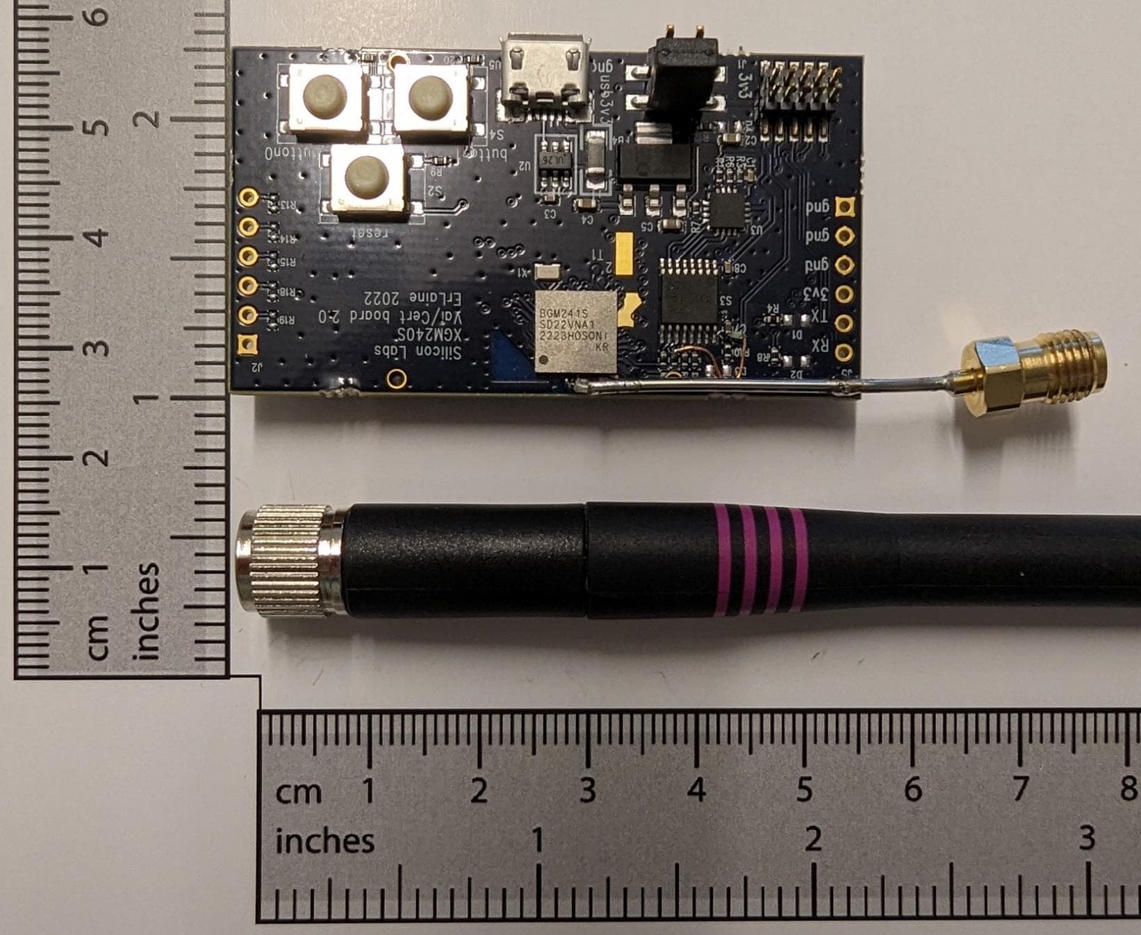
QOQ-GM241S
Sep 05, 2023Bluetooth Low Energy wireless radio module with Channel Sounding
Equipment Class
DTS - Digital Transmission System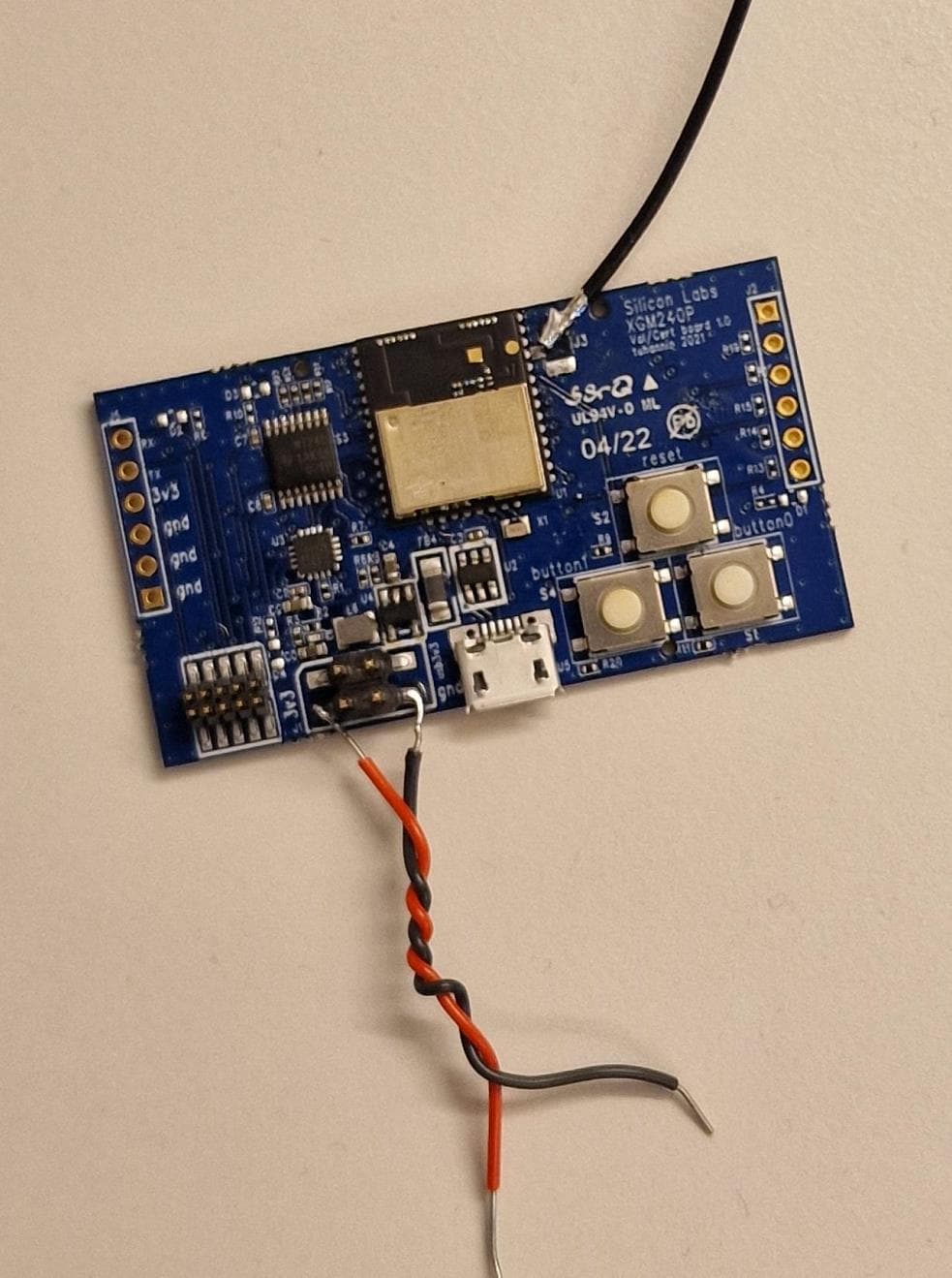
QOQ-GM240P
Aug 25, 2022Bluetooth Low Energy and 802.15.4 wireless radio module
Equipment Class
DTS - Digital Transmission System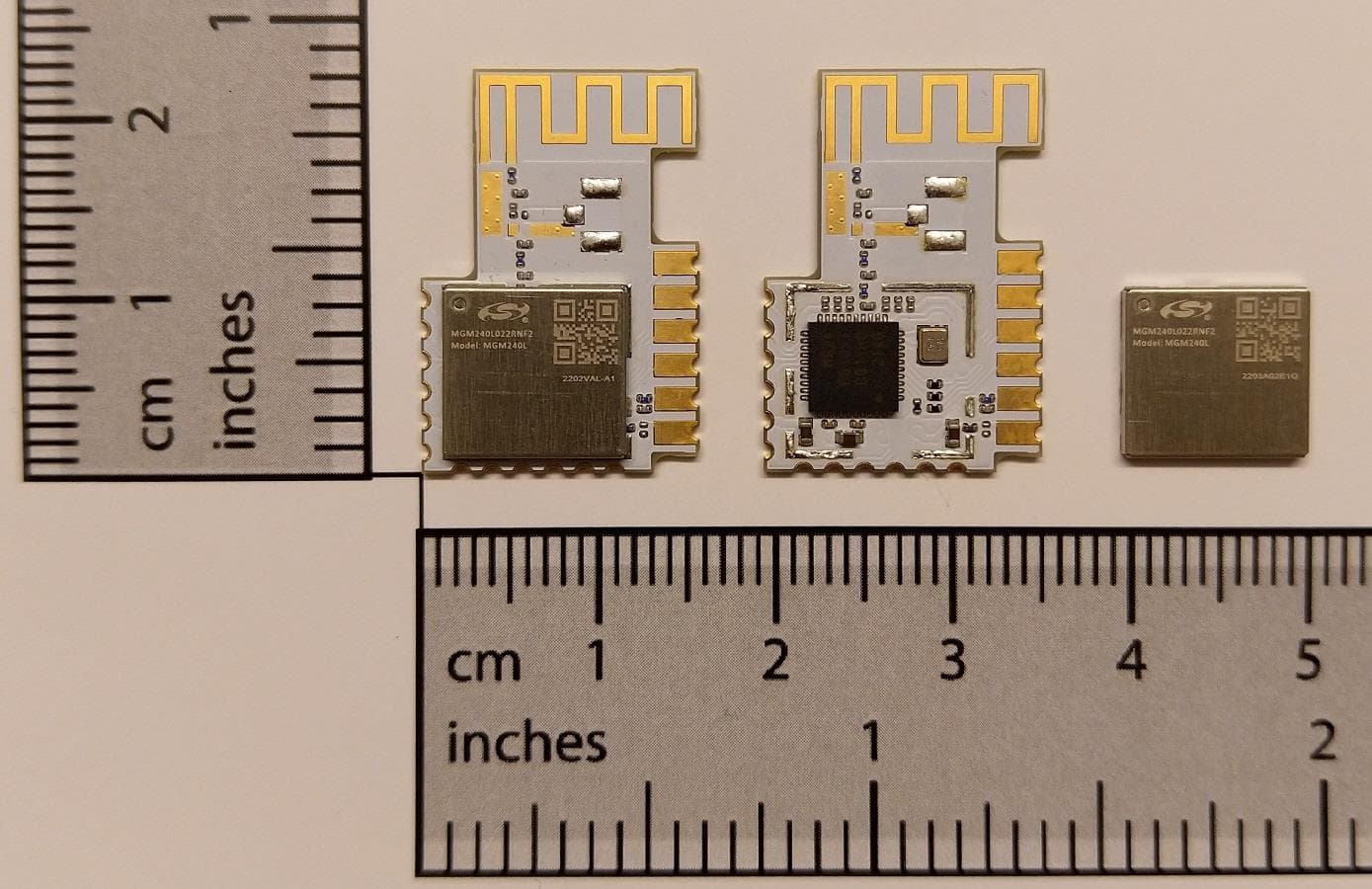
QOQ-MGM240L
Aug 20, 2022Radio Module with BLE and 802.15.4
Equipment Class
DTS - Digital Transmission System