QPI-RFMODULE01Transmitter Module
Heat-Timer Corporation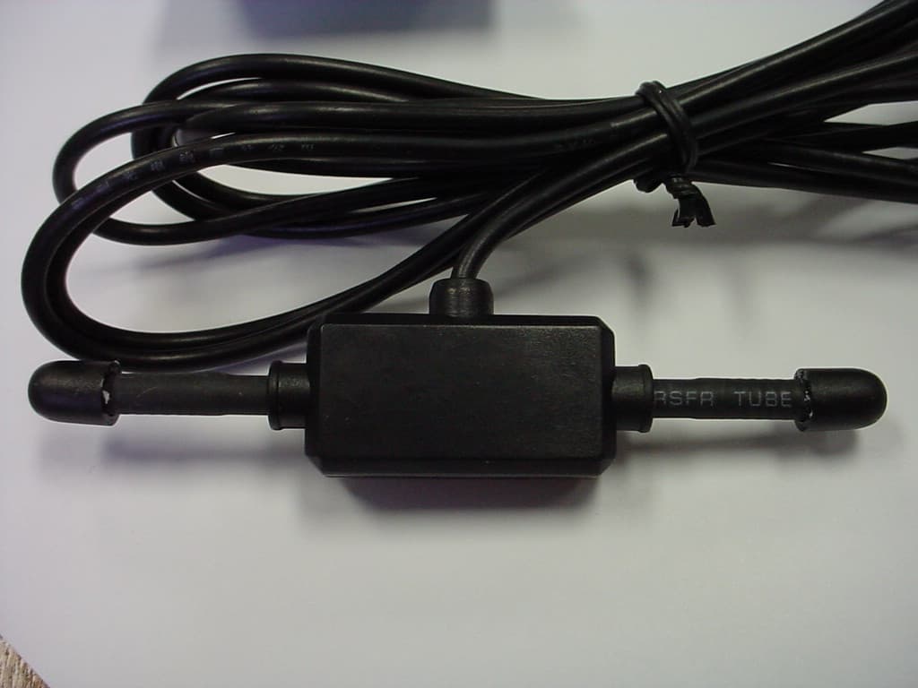
Click to zoom
Application Details
- Equipment Class
- DSS - Part 15 Spread Spectrum Transmitter
- Date of Grant
- Mar 20, 2006
- Application Purpose
- Original Equipment
- Date of Application
- Mar 20, 2006
- Equipment Note
- Transmitter Module
- Frequency Range
- 903.00000000 - 927.00000000
- Company
- Heat-Timer Corporation
- Country
- United States
Documents & Files
Document Text
Text extracted from the exhibit documents filed with the FCC. Open a document above to read the original.
Users Manual
RF Module User Manual 20 New Dutch Lane ♦ Fairfield, NJ 07004 Tel: (973) 575-4004 ♦ Fax: (973) 575-4052 HTC Product # Doc # Rev. Date Prepared by WWW.Heat-Timer.com xxxxxx-xx EDR119 C 2/6/06 Oron Brokman EDR119C RF Module User Manual.doc Page 1 of 2 3/21/2006 Follow the instructions below when integrating the module into the final product in order to make sure the final product complies with FCC requirements. 1. Use the module with the approved antennae only: use either a wire antenna or Antenna Factor’s p/n ANT-916-CW-RH, or Antenna Factor’s p/n ANT-900-MHW-RPS. 2. The power output at the RF connector should not exceed 250mW for the approved 0dB gain antennae and it should not exceed 125mW for the 3db antenna – the antennae listed above. 3. The voltage supply to the power amplifier should not exceed 3.6V +/- 0.2V. 4. Supply voltage to the VCC and VBAT pins should not exceed 3.6V +/- 0.2V. 5. All I/O pins are CMOS type. Current source/sink is 20mA max. 6. Connectors descriptions: a. J1 – used for antenna connection. b. J4 – used for mechanically supporting the module to the board with which it interfaces. c. J2 – used for in circuit programming of the microprocessor using Microchip’s ICD2 or equivalent. d. J1 – used for interfacing the module to the outside circuitry. For further pin functionality, refer to the schematic drawing and the data sheet of the microprocessor. RF Section uP J4 1 1 J2 J3 1 Compliance Statement (Part 15.19) This device complies with Part 15 of the FCC Rules. Operation is subject to the following two conditions: 1. This device may not cause harmful interference, and 2. This device must accept any interference received, including interference that may cause undesired operation. Warning (Part 15.21) Changes or modifications not expressly approved by the party responsible for compliance could void the user’s authority to operate the equipment. RF Module User Manual 20 New Dutch Lane ♦ Fairfield, NJ 07004 Tel: (973) 575-4004 ♦ Fax: (973) 575-4052 HTC Product # Doc # Rev. Date Prepared by WWW.Heat-Timer.com xxxxxx-xx EDR119 C 2/6/06 Oron Brokman EDR119C RF Module User Manual.doc Page 2 of 2 3/21/2006 Responsibility to the FCC Rules and Regulations WARNING! This module is to be installed only in Heat Timer Corporation’s end products by Heat Timer Trained Personnel, and shall not be offered to 3rd party OEM integrators or the general public. The RF Module has been certified per FCC Part 15 rules for integration into products without further testing or certification. The RF Module is labeled with its own FCC ID Number. If the FCC ID is not visible when the module is installed inside another device, then the outside of the device into which the module is installed must also display a label referring to the enclosed module. This exterior label can use wording such as the following: “Contains Transmitter Module FCC ID: QPI-RFMODULE01” or “Contains FCC ID: QPI-RFMODULE01” The RF Module must only use the approved antenna, which has been certified with this module. The final product configuration must be tested to comply with Unintentional Radiator Limits before declaring FCC compliance per Part 15 of the FCC rules. Industry Canada Statement The term "IC" before the certification / registration number only signifies that the Industry Canada technical specifications were met. Section 5.5 of RSS-210 This device has been designed to operate with an antenna having a maximum gain of [3] dB. Antenna having a higher gain is strictly prohibited per regulations of Industry Canada. The required antenna impedance is [ 50] ohms." Section 5.11 of RSS-210 To reduce potential radio interference to other users, the antenna type and its gain should be so chosen that the equivalent isotropically radiated power (EIRP) is not more than that required for successful communication. The module is to be installed only in Heat Timer Corporation’s end products by Heat Timer Trained Personnel, and will not be provided to 3rd party OEM integrators. To comply with FCC’s RF exposure limits for general population/uncontrolled exposure, the antenna(s) used for this transmitter must be installed to provide a separation distance of at least 20 cm from all persons. The antenna used for this module must not be collocated or operating in conjunction with any other antenna or transmitter.
Cover Letter(s)
20 New Dutch Lane ♦ Fairfield, NJ 07004 Tel: (973) 575-4004 ♦ Fax: (973) 575-4052 WWW.Heat-Timer.com STEAM HEATING CONTROLS RADIANT HEAT CONTROLS ONE PIPE STEAM AIR VENTS HYDRONIC HEATING CONTROLS DIGITAL SET POINT CONTROLS MOTORIZED VALVES SEQUENCING CONTROLS TEMPERING VALVES SNOW MELT CONTROLS FCC CONFIDENTIALITY Date: 1/27/06 Time: 11:00 To: FCC Authorization & Evaluation Division 7435 Oakland Mills Road Columbia, MD 21045-0429 From: Oron Brokman Phone: 973 - 575 – 4004 Senior Design Engineer Fax: 973 - 575 - 4052 Applicant: Heat Timer Corporation. E-Mail: [email protected] __________________________________________________________________________________________________ Subject: Request for Non disclosure for FCC ID: QPI – RFMODULE01. To Whom It May Concern: Pursuant to 47 CFR Section 0.459, Heat Timer Corporation hereby requests non disclosure and confidential treatment of the following materials submitted in support of FCC certification application for FCC ID: QPI – RFMODULE01. a. Schematic Diagrams b. Operational Description c. Block Diagram Above materials contain trade secrets, proprietary and technical information which would customarily be guarded from competitors under 47 CFR section 0.457(d)(2). Disclosure or publication of any portion of this company confidential material to other parties could cause substantial competitive harm and provide unjustified benefits for competitors. Heat Timer Corporation understands that pursuant to 47 CFR section 0.457(d)(1)(ii) disclosure of the applicant and all accompanying documentation will not be made before the date of the grant. Sincerely yours, By: Oron Brokman Title: Senior Design Engineer / Heat Timer Corporation
Cover Letter(s)
20 New Dutch Lane ♦ Fairfield, NJ 07004 Tel: (973) 575-4004 ♦ Fax: (973) 575-4052 WWW.Heat-Timer.com STEAM HEATING CONTROLS RADIANT HEAT CONTROLS ONE PIPE STEAM AIR VENTS HYDRONIC HEATING CONTROLS DIGITAL SET POINT CONTROLS MOTORIZED VALVES SEQUENCING CONTROLS TEMPERING VALVES SNOW MELT CONTROLS FCC A U T H O R I Z A T I O N Date: 1/27/06 Time: 11:00 To: FCC Authorization & Evaluation Division 7435 Oakland Mills Road Columbia, MD 21045-0429 From: Oron Brokman Phone: 973 - 575 – 4004 Senior Design Engineer Fax: 973 - 575 - 4052 Applicant: Heat Timer Corporation. E-Mail: [email protected] __________________________________________________________________________________________________ Dear Ladies and/or Gentlemen: I appoint Kenneth L. Boston, James Blaha and Teresa White at L.S. Compliance, Inc., to act as an agent in the preparation of applications under Part 15 of the rules and regulations of the Federal Communications Commission. I certify that the exhibitions properly describe the device being submitted under this application and will implement any changes described in the test report. The labels described will be affixed to each item. The following statement is required by the Federal Communications Commission: By checking Yes, the applicant certifies that, in the case of an individual applicant, he or she is not subject to a denial of federal benefits, that included FCC benefits, pursuant to section 5301 of the Anti-Drug Abuse Act of 1988, 21 U.S.C 853(a), or, in the case of a non-individual applicant (e.g. corporation, partnership, or other unincorporated association), no party to the application is subject to a denial of federal benefits, that includes FCC benefits, pursuant to that section. ___X___Yes _______No By: Oron Brokman Title: Senior Design Engineer / Heat Timer Corporation
Cover Letter(s)
Modular Transmitter Requirements for FCC ID: QPI-RFMODULE01 20 New Dutch Lane ♦ Fairfield, NJ 07004 Tel: (973) 575-4004 ♦ Fax: (973) 575-4052 HTC Product # Doc # Rev. Date Prepared by WWW.Heat-Timer.com xxxxxx-xx EDR122 A 2/10/06 Oron Brokman 8 point modular letter 2/10/2006 February 9, 2006 Re: Limited Modular Transmitter Approval FCC ID: QPI-RFMODULE01 Gentlemen, The following information is being provided per the requirements of DA00-1407 regarding limited modular approval of Part 15 devices. This transceiver is a complete RF module with an integral reference oscillator. External connections are provided for power, data communication, and antenna. The following numbered items correspond to similarly numbered paragraphs in DA00-1407. Each item is a response to the requirements of that document. 1) The module has integral RF shielding to isolate it from surrounding equipment and the larger environment in general. 2) All inputs are processed as data by the on-board microcontroller. The outside user has no direct control of transmit modulation. 3) There are two hardware voltage regulators on board. The power amplifier voltage is hard-limited to 3.6V by an internal company requirement and is documented. The module will not be offered for sale to external parties. 4) A reverse gender SMA style connector is employed to prevent the use of antennas other than the type specified. This is in accordance with Part 15.203. 5) The module was tested in a stand-alone configuration and found to be compliant with Part 15 regulations. 6) An FCC ID label is affixed to each unit at the time of manufacture. Information is also clearly presented in the user guide about labeling requirements for the final assembly. 7) This unit is compliant with Part 15.247. Installation and other requirements are presented in the user guide to allow the unit to be correctly installed. 8) The unit is compliant with the RF exposure requirements of Parts 15.247, 15.1091, and 15.1093. Sincerely, Oron Brokman Senior Design Engineer Heat Timer Corporation
Cover Letter(s)
The RH Series is designed to offer near straight monopole performance in an ultra-compact package. Ideal for small products where cosmetic or functional requirements dictate a compact, aesthetically pleasing antenna pack- age. Despite their tiny size, RH Series antennas are ruggedly constructed and able to withstand punishing environments just like our larger whips. Features Electrical Specifications Reduced-height helical whip Low VSWR Excellent performance Omni-directional pattern Fully weatherized Rugged construction Damage-resistant Part 15 compliant RP-SMA connector Use with plastic* or metal enclosures * Requires proximity ground plane ANT-916-CW-RH DATA SHEET Product DimensionsDescription Plots Antenna Factor575 S.E. Ashley Place Grants Pass, OR 97526-3237 www.antennafactor.com 541-956-0931 (phone) 541-471-6251 (fax) Rev 07-26-05 AzimuthElevationTypical VSWR 270 90 180 0 -30dB -25dB -20dB -15dB -10dB - 5dB 0dB 5dB 10dB 270 90 180 0 -30dB -25dB -20dB -15dB -10dB - 5dB 0dB 5dB 10dB Coming Soon Coming Soon Coming Soon Coming Soon 2.00” (51.0) 0.39” (10.0) 0.15” (3.8) 0.31” (8.0) 0.14” (3.6) End View 0.33” (8.5) CENTER 916.000MHz SPAN 75.000MHz S11 SWR 1.733 Center Freq. Bandwidth Wavelength VSWR Impedance Gain Connector 916MHz 35MHz 1/4-wave <1.9 typ. at center 50 ohms TBD RP-SMA Note: Electrical specifications and plots measured on 4” x 4” reference ground plane Ordering Information ANT-916-CW-RH
Cover Letter(s)
SPECIFICATIONANT-418-MHW-RPSANT-433-MHW-RPSANT-916-MHW-RPS Frequency Range410-426425-441881-951 Bandwidth161670 Gain2dBi2dBi2dBi V.S.W.R.<1.5<1.5<1.5 Impedance50Ω50Ω50Ω Max Power50W50W50W Length12cm12cm10cm ConnectorRP-SMARP-SMARP-SMA Cable79”79”79” ELECTRICAL SPECIFICATIONS SPECIFICATION SHEET MHW SERIES ANTENNAS For additional information, please contact Antenna Factor at 800-489-1634 Recipient understands any or all of the above specifications are subject to change without notice and proceeds with integration at own risk. Revised 7/3/01 PART #DESCRIPTION ANT-418-MHW-RPS418MHz MHW Series Antenna ANT-433-MHW-RPS433MHz MHW Series Antenna ANT-900-MHW-RPS916MHz MHW Series Antenna ORDERING INFORMATION 0.36" 0.69" 1.90" - 916MHz 2.85" - 418MHz 1.32" 0.27" 0.03" (Adhesive Pad) RP-SMA Connector Standard. Other terminations available for volume orders.
ID Label/Location Info
http://www.bradyid.com/tds/tdsv1r0.nsf/ESearchIndex/B423 1 of 31/31/2006 9:17 AM Technical Data Sheet BRADYBONDZ(TM) B-423 THERMAL TRANSFER PRINTABLE GLOSSY WHITE POLYESTER LABEL STOCK TDS No. B-423 Effective Date: 03-Jun-2004 Description: GENERAL Print Technology: Thermal transfer Materials Type: White polyester Finish: Glossy white Adhesive: Permanent acrylic APPLICATIONS Electronic PCB and component identification, bar code label and rating plates. RECOMMENDED RIBBONS Brady series R6000 Brady series R4400 (colors - red, blue, green, white) Brady series R4900 and R6200 (alternates) AGENCY APPROVALS UL: B-423 is a UL Recognized Component to UL969 Labeling and Marking Standard when printed with Brady Series R6000 ribbon. See UL file MH17154 for specific details. UL information can be accessed on line at UL.com. Search in Certifications area. The Brady Series R4900 ribbon is also UL approved. CSA: B-423 is CSA Accepted to C22.2 No.0.15-95 Adhesive Labels Standard when printed with Brady Series R6000 ribbon. See CSA file 041833 for specific details. CSA information can be accessed online at directories.csa-international.org. DIN VDE 0472 Part 815: Brady B-423 meets requirements of a halogen-free material per DIN VDE 0472 part 815. (Statement based on review of product construction and confirmation halogen content test run at an independent test laboratory.) Details: PHYSICAL PROPERTIESTEST METHODSAVERAGE RESULTS ThicknessASTM D 1000 -Substrate -Adhesive -Total 0.002 inch (0.0508 mm) 0.001 inch (0.0254 mm) 0.003 inch (0.0762 mm) Adhesion to: -Stainless Steel - Painted Enamel - Textured ABS ASTM D 1000 20 minute dwell 24 hour dwell 20 minutes dwell 24 hour dwell 20 minutes dwell 24 hour dwell 51 oz/inch (56 N/100 mm) 78 oz/inch (85 N/100 mm) 54 oz/inch (59 N/100 mm) 67 oz/inch (73 N/100 mm) 10 oz/inch (11 N/100 mm) 15 oz/inch (17 N/100mm) TackASTM D 2979 Polyken™ Probe Tack 1 second dwell 21 oz (600 g) Dielectric StrengthASTM D 10008600 Volts B-423 is not recommended for low surface energy surfaces such as polyethylene and polypropylene. Performance properties tested on B-423 printed with Series R6000 and R6200 ribbons using the Bradyprinter™ THT Model 300X-Plus thermal transfer printer. Printed samples were laminated to aluminum and allowed to dwell 24 hours before exposure to the indicated environments. Unless noted, results are the same for both ribbons. PERFORMANCE PROPERTIESTEST METHODTYPICAL RESULTS http://www.bradyid.com/tds/tdsv1r0.nsf/ESearchIndex/B423 2 of 31/31/2006 9:17 AM High Service Temperature30 days at various temperaturesNo visible effect to label at 110°C. Slight discoloration at 120°C; moderate discoloration at 145°C but label is still functional. Low Service Temperature30 days at -70°CNo visible effect Short Term High Service Temperature5 minutes at various temperaturesNo visible effect to label at 180°C. Slight discoloration and label shrinkage at 200°C; label is functional. Label becomes nonfunctional at 210°C due to label shrinkage. Humidity Resistance30 days at 100°F (37°C) and 95% relative humidity. No visible effect UV Light Resistance30 days in UV Sunlighter™ 100Slight discoloration WeatherabilityASTM G26 30 days in Xenon Arc Weatherometer No visible effect Salt Fog ResistanceASTM B 117 30 days in 5% salt fog solution chamber No visible effect PERFORMANCE PROPERTYCHEMICAL RESISTANCE Samples were printed with Series R6000 and R6200 ribbons using a Bradyprinter™ 300X-Plus thermal transfer printer. Samples were laminated to aluminum panels and allowed to dwell 24 hours prior to testing. Testing was conducted at room temperature and consisted of 30 minute immersions in the specified test fluid. After immersion, the samples were removed from the test fluid and the printed image rubbed 10 times with a cotton swab saturated with the test fluid. The rating scale below shows the effect to the quality of the print for each sample. CHEMICAL REAGENT SUBJECTIVE OBSERVATION OF VISUAL CHANGE EFFECT TO LABEL STOCK EFFECTS TO PRINTED IMAGE R6000R6200 WITHOUT RUBWITH RUBWITHOUT RUBWITH RUB AcetoneSlight adhesive ooze 1515 TolueneSlight adhesive ooze 1515 Isopropyl AlcoholNo visible effect1111 Mineral SpiritsNo visible effect1111 GasolineSlight adhesive ooze 1111 JP-8 Jet FuelSlight adhesive ooze 1111 Brake FluidNo visible effect11-215 Skydrol® 500B-4 Slight adhesive ooze 1525 SAE 20 WT Oil at 70°C No visible effect1111 MIL 5606 OilNo visible effect1111 Formula 409® Cleaner No visible effect1111 Northwoods™ Buzz Saw Citrus Degreaser No visible effect1111 Deionized WaterNo visible effect1111 Rating Scale: 1= no visible effect 2= slight smear or print removal, detectable but minimal smear 3= moderate smear or print removal (print still legible) 4= severe smear or print removal (print illegible or just barely legible) 5= complete print and/or topcoat removal NP= print removed prior to rub http://www.bradyid.com/tds/tdsv1r0.nsf/ESearchIndex/B423 3 of 31/31/2006 9:17 AM Product testing, customer feedback, and history of similar products, support a customer performance expectation of at least two years from the date of receipt for this product as long as this product is stored in its original packaging in an environment below 80 degrees F and 60% RH . We are confident that our product will perform well beyond this time frame. However, it remains the responsibility of the user to assess the risk of using such product. We encourage customers to develop functional testing protocols that will qualify a product’s fitness for use, in their actual applications. Trademarks: BradyBondz™ is a trademark of Brady Worldwide, Inc. BradyPrinter™ is a trademark of Brady Worldwide, Inc. Formula 409® is a registered trademark of the Clorox Company Northwoods™ is a trademark of the Superior Chemical Corporation Polyken™ is a trademark of Testing Machines Inc. Skydrol® is a registered trademark of the Monsanto Company Sunlighter™ is a trademark of the Test Lab Apparatus Company ASTM: American Society for Tes…
Text truncated - open the document above for the full version.
ID Label/Location Info
This device complies with Part 15 of the FCC Rules. Operation is subject to the following two conditions: 1) this device may not cause harmful interference, and 2) this device must accept any interference received, including interference that may cause undesired operation. Heat Timer Corp. IC: 6342A-RFXCVR01 P/N 900271-01 FCC ID: QPI-RFMODULE01 Size: 3/8”x3/4”
Internal Photos
Heat-Timer Corporation RF Module FCC ID#: QPI-RFMODULE01 Photo One – Internal Shield Removed, Showing RF Section Heat-Timer Corporation RF Module FCC ID#: QPI-RFMODULE01 Photo Two – Internal Flip Side of PCB Module Heat-Timer Corporation RF Module FCC ID#: QPI-RFMODULE01 Photo Three – Internal Wire Antenna Connection Heat-Timer Corporation RF Module FCC ID#: QPI-RFMODULE01 Photo Four – Internal Remote Antenna Connection – Reverse SMA Heat-Timer Corporation RF Module FCC ID#: QPI-RFMODULE01 Photo Five – Internal Lynx Antenna Heat-Timer Corporation RF Module FCC ID#: QPI-RFMODULE01 Photo Six – Internal Remote Antenna Connected Heat-Timer Corporation RF Module FCC ID#: QPI-RFMODULE01 Photo Seven – Internal Close Up of DiPole Antenna Heat-Timer Corporation RF Module FCC ID#: QPI-RFMODULE01 Photo Eight – Internal DiPole Antenna Connection
RF Exposure Info
L.S. Compliance, Inc. Page 48 of 53 Test Report Number: 305440-Tx-v1 Prepared For: Heat-Timer Corporation 21. MPE Calculations 900 MHz Transceiver Module MPE Calculation based on the highest gain antenna configuration Configuration Antenna MFG Model Gain 1 Antenna Factor ANT-916-CW-RH 2.5 dBi 2 Antenna Factor ANT-916-MHW-RPS 2.0 dBi 3 “Generic Wire Whip” 8 cm long, 22 AWG 4.1 dBi (Note 1) Notes: 1) The antenna gain was calculated based on empirical electric field intensity measurements above a conductive ground plane. The antenna gain figure listed is not free-space antenna gain. Prediction of MPE limit at a given distance Equation from page 18 of OET Bulletin 65, Edition 97-01 where:S = power density P = power input to the antenna G = power gain of the antenna in the direction of interest relative to an isotropic radiator R = distance to the center of radiation of the antenna Maximum peak output power at antenna input terminal:22.80 (dBm) Maximum peak output power at antenna input terminal:190.546 (mW) Antenna gain(typical):4.1(dBi) Maximum antenna gain:2.570 (numeric) Prediction distance:20 (cm) Prediction frequency:915 (MHz) MPE limit for uncontrolled exposure at prediction frequency:0.62 (mW/cm^2) Power densit y at prediction frequency:0.097438(mW/cm^2) Maximum allowable antenna gain:12.1 (dBi) 20cm =8.0 dB Margin of Compliance at 2 4R PG S π =
Test Report
L.S. Compliance, Inc. W66 N220 Commerce Court Cedarburg, WI 53012 262-375-4400 Fax: 262-375-4248 COMPLIANCE TESTING OF : Heat-Timer 900 MHz RF Module Prepared For: Heat-Timer Corporation Attention: Mr. Oron Brokman 20 New Dutch Lane Fairfield, NJ 07004 U.S.A. Test Report Number: 305440-Tx-v1 Test Dates: February 8 TH , through 24 TH , 2006 All results of this report relate only to the items that were tested. This report is not to be reproduced, except in full, without written approval of L. S. Compliance, Inc. L.S. Compliance, Inc. Page 2 of 53 Test Report Number: 305440-Tx-v1 Prepared For: Heat-Timer Corporation Table of Contents Section Description Page Index 2 1 L. S. Compliance in Review 3 2 Signature Page 4 3 Product and General Information 5 4 Introduction 5 5 Product Description 6-7 6 Test Requirements 8 7 Summary of Test Report 8 8 Radiated Emissions Test 9-25 9 Band-Edge Measurements 26 10 Conducted Emissions onto AC Power Line 27-31 11 Occupied Bandwidth 32-33 12 RF Power Output 34-35 13 Spurious RF Emissions 36-37 14 Minimum Channel Separation 38-41 15 Channel Occupancy 42-44 16 Frequency and Power Stability requirements 45 17 Equal Channel Usage 46 18 Pseudorandom Hopping Pattern 46 19 Receiver Synchronization 47 20 Receiver Input Bandwidth 47 21 MPE Calculations 48 Appendix A Test Equipment List 49 B Antenna Specification Sheets 50-52 C Firmware and Setup Instructions 53 L.S. Compliance, Inc. Page 3 of 53 Test Report Number: 305440-Tx-v1 Prepared For: Heat-Timer Corporation 1. L. S. Compliance In Review L.S. Compliance - Accreditations and Listing’s As an EMC Testing Laboratory, our Accreditation and Assessments are recognized through the following: A2LA – American Association for Laboratory Accreditation Accreditation based on ISO/IEC 17025 : 1999 with Electrical (EMC) Scope of Accreditation A2LA Certificate Number: 1255.01 Federal Communications Commission (FCC) – USA Listing of 3 Meter Semi-Anechoic Chamber based on Title 47 CFR – Part 2.948 FCC Registration Number: 90756 Industry Canada On file, 3 Meter Semi-Anechoic Chamber based on RSS-212 – Issue 1 File Number: IC 3088-A On file, 3 and 10 Meter OATS based on RSS-212 – Issue 1 File Number: IC 3088 U. S. Conformity Assessment Body (CAB) Validation Validated by the European Commission as a U. S. Competent Body operating under the U. S. /EU, Mutual Recognition Agreement (MRA) operating under the European Union Electromagnetic Compatibility –Council Directive 2004/108/EC (formerly 89/336/EEC, Article 10.2) Date of Validation: January 16, 2001 Validated by the European Commission as a U.S. Notified Body operating under the U.S./EU, Mutual Recognition Agreement (MRA) operating under the European Union Telecommunication Equipment – Council Directive 99/5/EC, Annex V. Date of Validation: November 20, 2002 Notified Body Identification Number: 1243 L.S. Compliance, Inc. Page 4 of 53 Test Report Number: 305440-Tx-v1 Prepared For: Heat-Timer Corporation 2. Signature Page Prepared By: March 9, 2006 Teresa A. White, Document Coordinator Date Tested By: March 9, 2006 Abtin Spantman, EMC Engineer Date Approved By: March 9, 2006 Brian E. Petted, VP of Engineering Date L.S. Compliance, Inc. Page 5 of 53 Test Report Number: 305440-Tx-v1 Prepared For: Heat-Timer Corporation 3. Product and General Information Manufacturer: Heat-Timer Corporation Date(s) of Test: February 8 TH through 24 TH , 2006 Test Engineer(s): Tom Smith √ Abtin Spantman Ken Boston Model #: 900 MHz RF Module Serial #: 05510529 and 05510534 Voltage: 3.3 VDC Operation Mode: Normal, continuous modulated transmit, and ‘Hopping’ mode 4. Introduction Between February 8 TH and 24 TH , 2006, a series of Conducted and Radiated RF Emission tests were performed on two samples of the Heat-Timer Corporation’s 900 MHz RF Modules, serial numbers 05510529 and 05510534, here forth collectively referred to as the “Equipment Under Test” or “EUT”. These tests were performed using the procedures outlined in ANSI C63.4-2003 for intentional radiators, and in accordance with the limits set forth in FCC Part 15.247 (Industry Canada RSS-210) for a low power transmitter. These tests were performed by Abtin Spantman, EMC Engineer at L.S. Compliance, Incorporated. All Radiated and Conducted RF Emission tests were performed upon the EUT to measure the emissions in the frequency bands described in FCC Title 47 CFR Part 15, including 15.35, 15.209, 15.247 and Industry Canada RSS-210 to determine whether these emissions are below the limits expressed within the standards. These tests were performed in accordance with the procedures described in the American National Standard for methods of measurement of Radio- Noise Emissions from Low-Voltage Electrical and Electronic Equipment in the Range of 9 kHz to 40 GHz (ANSI C63.4-2003). Another document used as a reference for the EMI Receiver specification was the Comite International Special Des Perturbations Radioelelectriques (CISPR) Number 16-1, 2003. All tests were performed at L.S. Compliance, Inc., in Cedarburg, Wisconsin, unless otherwise noted. L.S. Compliance, Inc. Page 6 of 53 Test Report Number: 305440-Tx-v1 Prepared For: Heat-Timer Corporation 5. Product Description The Heat-Timer 900 MHz RF Module is a Frequency Hopping transceiver module operating in the 902-928 MHz ISM band, as qualified under 47CFR Part 15.247. The transmit characteristics of this transceiver were tested and the results are covered in this report. The module has a 3.3 VDC, 175 mA nominal voltage and current requirement, and is designed to operate on 25 channels, with a nominal RF power output of 250 mW. The module may be powered from batteries or from AC wall adaptors. Power and data pins are available through a standard 0.1” header on the module. The module may be fitted with a reverse gendered SMA connector for the different antennas, or with a wire whip antenna directly soldered onto the module. The Module is based on a single chip RF transceiver processor, which is capabl…
Text truncated - open the document above for the full version.
Test Setup Photos
Heat-Timer Corporation Test Setup Photos Page 1 of 10 The Heat-Timer 900 MHz RF Transceiver Module, shown with the SMA-RP connector configuration. The Modules and antenna configurations shown on the right, And the test-board fixture shown on the left. Heat-Timer Corporation Test Setup Photos Page 2 of 10 Heat-Timer Corporation Test Setup Photos Page 3 of 10 View of the EUT setup in vertical orientation Antenna configuration 1 shown in this series of photos. View of the EUT setup in Horizontal orientation Heat-Timer Corporation Test Setup Photos Page 4 of 10 View of the EUT setup in Side orientation Heat-Timer Corporation Test Setup Photos Page 5 of 10 Front view of the EUT setup on the test stand as seen from the sense antenna. Rear view of the EUT setup showing the wire draping. Heat-Timer Corporation Test Setup Photos Page 6 of 10 Heat-Timer Corporation Test Setup Photos Page 7 of 10 View of the EUT antenna defined in vertical orientation, with module PCB in various orientation. Antenna configuration 2 shown in this series of photos. View of the EUT antenna setup in Horizontal orientation Heat-Timer Corporation Test Setup Photos Page 8 of 10 View of the EUT setup in vertical orientation Antenna configuration 3 shown in this series of photos. View of the EUT setup in Horizontal orientation Heat-Timer Corporation Test Setup Photos Page 9 of 10 View of the EUT setup in Side orientation Heat-Timer Corporation Test Setup Photos Page 10 of 10 Setup for the Conducted Emissions Test
Contact Information
Applicant
Carlos Urbina(Engineering Manager)
Test Firm
L. S. Compliance, Inc.James Blaha
262-375-4400Fax: 262-375-4248
Technical Specifications
| # | Rule Parts | Frequency Range | Power Output |
|---|---|---|---|
| 1 | 15C | 903 MHz - 927 MHz | 191.00 mW |
Other Applications from Heat-Timer Corporation
QPISLROOMTMP01
Jul 28, 2004Sensor Link Room Temperature Transmitter
Equipment Class
DXX - Part 15 Low Power Communication Device Transmitter
QPISLROOMTMP00
Jan 07, 2003Sensor Link Room Temperature Transmitter
Equipment Class
DXX - Part 15 Low Power Communication Device Transmitter