QPISLROOMTMP00Sensor Link Room Temperature Transmitter
Heat-Timer Corporation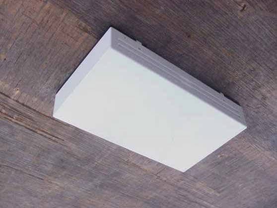
Click to zoom
Application Details
- Equipment Class
- DXX - Part 15 Low Power Communication Device Transmitter
- Date of Grant
- Jan 07, 2003
- Application Purpose
- Original Equipment
- Date of Application
- Jan 07, 2003
- Equipment Note
- Sensor Link Room Temperature Transmitter
- Frequency Range
- 915.35100000 - 915.35100000
- Company
- Heat-Timer Corporation
- Country
- United States
Documents & Files
Document Text
Text extracted from the exhibit documents filed with the FCC. Open a document above to read the original.
Users Manual
SENSOR LINK INSTALLATION/OPERATING INSTRUCTIONS The Sensor Link system consists of a Receiver and one or more Temperature or Pressure Transmitters. The Receiver is designed to intercept and decode the wireless information being emitted by the Transmitters and forward the data to the Heat-Timer panel (HWR, HWR-Q, MPC, MPC-Q, SRC, or Multi- MOD) via a wired connection. Instruction to User This equipment has been tested and found to comply with the limits for a class B digital device, pursuant to part 15 of the FCC Rules. These limits are designed to provide reasonable protection against harmful interference in a residential installation. This equipment generates, uses and can radiate radio frequency energy and if not installed and used in accordance with the instructions, may cause harmful interference to radio communications. However, there is no guarantee that interference will not occur in a particular installation. If this equipment does cause harmful interference to radio or television reception, which can be deter- mined by turning the equipment off and on, the user is encouraged to try to correct the interference by one or more of the following measures: * Reorient or relocate the receiving antenna. * Increase separation between the equipment and receiver. * Connect the equipment into an outlet on a circuit different from that to which the receiver is connected. * Consult the dealer or an experienced radio/TV technician for help. This equipment has been certified to comply with the limits for a class B computing device, pursuant to FCC Rules. In order to maintain compliance with FCC regulation, shielded cables must be used with this equipment. Operation with non-approved equipment or unshielded cables is likely to result in interference to radio and TV reception. The user is cautioned that changes or modifications made to the equipment without the approval of the manufacturer could void the userís authority to operate this equipment. PROGRAM LOCK THERMAL LOCKOUT DIFFERENTIAL E PRESS TO DISPLAY MADE IN U.S.A. CONNECTED MUST CLOCKNEUTRAL LINE 132 OPTION READ INSTRUCTIONS BEFORE PROGRAMMING PROGRAM BER B OUTPUT W 12 34 56 AUX.OPTION 7 8 9 10121113 OUTPUT RELAY UNLOCK BY-PASS AUTO CLOCK AUX. 1 OPTION SUMMER WINTER RUN N C R ADJUSTMENT BOOST VARI OPTIONOPTION 17141516 MANUAL X WITH VARI SHUT DOWN Z ON I 3 OPTION 2 ADVANCE REVIEW PAIR SHOWN ERASE Y HEATING SYSTEM SENSOR A S E OFF FAST CYCLE FOR TESTING MORNING BOOST 120 SHUT DOWN CURVE Series (DAY) SYSTEM IN NORMAL AM TUE N HEAT ADJUSTMENT SYSTEM IN SAVE (NIGHT) OUTDOOR SENSOR SET POINTS SHIFT HOURS MON CURRENT STATUS INDICATORS E A L C B P O NORMAL H G F E S S D J K M L -DAY I THU CLOCK PROGRAM CONTROLS MINUTES PM DAY WEDSATFRI SUN TEMP 2 COPYDAY OFF MANUAL MINUTES VARI-BOOST / 1 20 OUT- SIDE40 3 60 4 80 BOOST K -NIGHT R E A L E C B SAVE F S S O M D E GJ H I R P E N O M O L M Gold SERIAL NO. 5 6 100 USE COPPER WIRE ONLY OUTPUTS: 120VAC, 6A RESISTIVE 1A PILOT DUTY 15A TOTAL FOR ALL CIRCUITS HEAT-TIMER PANEL HWR, HWRQ, MPC, MPCQ, SRC, Multi-MOD HEAT SOURCE ACTIVATED HEAT CIRCULATION ESTABLISHED SYSTEM IN CYCLE J1 X1 X2 X3 120 VAC Power Sensor Link Receiver Sensor Link Transmitter SENSOR LINK RECEIVER INSTALLATION Mount the enclosure ï In a location central to the various Transmitters. ï To prevent unauthorized tampering, the Receiver should be located in an inconspicuous area, or in an area with limited access. ï The Receiver must be located where the ambient temperature will not exceed 130∞F and away from any steam or moisture. ï Attach the Receiver to a flat surface by screwing through the mounting holes located on the top and bottom flange. ï If desired, the Receiver may also be installed inside a metal enclo- sure. Power Wiring ï Bring the 120VAC 60Hz power wires through the round opening in the enclosure. ï Class 1 voltages must enter the enclosure through a different opening from any Class 2 voltage wiring. ï Connect power to the terminals as shown at right. ï The GND terminals MUST be connected to earth ground. Network Wiring ï Use 2-wire unshielded twisted pair (see specification below). ï There is no polarity to observe. Either network wire from the Receiver can be attached to Heat-Timer panel (HWR, HWRQ, MPC, MPCQ, SRC, or Multi-MOD) Network terminals A or B. ï Bring the network wiring through the rectangular opening in the enclosure. ï Network wiring must enter the enclosure through a different opening from any Class 1 voltage wiring. ï Wire the network connections to the terminal block marked J1, terminals X1 and X2. ï The wires can be run in virtually any configuration back to the Heat- Timer panel. They can be wired sensor to sensor (daisy chained). They can be wired in a star configuration, with each sensor pair brought back to the panel. Finally, there can be any combination of the two. ï The Receiver has a specific ID number. The ID number is on the back of the Receiver, and is on the Network Identification card which is provided. Fill out the location of the Receiver on the Network Identification card and return it to the Heat-Timer network adminis- trator. GND Neutral Line WireType Belden 8471 Belden 85102 Unshielded Twisted Pair 16AWG GaugeMaximum Length (ft)Maximum Temp (°F) Unshielded Twisted Pair 16AWG 1200 1200 140 185 J1 X1 X2 X3 To Network Terminals A &B SENSOR LINK RECEIVER OPERATION Power Up Display ï When the receiver is first powered, 8 will be displayed in each of the digits in turn, moving from right to left. ï Next the display will briefly show the version number, and then go blank. ï During this period, the green LED (D1), yellow LED (D2), and red LED (D3) will flash or light. ï When the display goes blank, only the red LED (D3) will remain on to indicate the Receiver is powered. Display Modes ï Pressing the push button will set the display mode for the Receiver. ï Once a display mode is selected, the Receiver will remain in the selected display mode until the push button is pressed and a new mode is selec…
Text truncated - open the document above for the full version.
Block Diagram
20 New Dutch Lane ♦ Fairfield, NJ 07004 Sensor Link Room Temperature Transmitter Block Diagram Tel: (973) 575-4004 ♦ Fax: (973) 575-4052 HTC Product # Doc # Rev. Date WWW.Heat-Timer.com 904710-00 EDR007 A 11/6/02 Block_Diagram 11/6/02 Page 1 of 1 In-Circuit Programming 4MHz Crystal Switch Attenuator Channel Select Data 10 to 18KHz 915MHz Microprocessor Pushbutton Transmitter Module Power Antenna Temperature Sensor 915MHz Power Supply - Batteries Voltage Detector 19200bd Data RTS Sensor Link Room Temperature Transmitter Block Diagram
Cover Letter(s)
114 OLINDA DRIVE • •• • BREA, CALIFORNIA 92823 • •• • (714) 579-0500 • •• • FAX (714) 579-1850 December 4, 2002 CETCB 114 Olinda Drive Brea, CA 92823 Subject: Request for Certification of the Heat Timer Corporation Sensor Link Room Temperature Transmitter Model: 904710-00 FCC ID: QPISLROOMTMP00 Gentlemen: We have enclosed a package for the certification of the Heat Timer Corporation Sensor Link Room Temperature Transmitter Model: 904710-00. We have enclosed the completed Form 731 with the applicable exhibits. If you have any questions or need any additional information, please give me a call at (714) 579-0500. Sincerely, Kyle Fujimoto Test Engineer
Cover Letter(s)
1 Scott McCutchan To: [email protected] Subject: FCC ID: QPISLROOMTMP00 Mr. Fujimoto, In order for processing of this application (FCC ID: QPISLROOMTMP00) to continue, the following issue(s) will have to be addressed: 1) Please provide a photograph or drawing showing where the FCC ID label will be placed on the device. The item(s) indicated above must be submitted before processing can continue on the above referenced application. Failure to provide the requested information within 60 days of the original e-mail date may result in application dismissal and forfeiture of the filing fee. Also, please note that partial responses increase processing time and should not be submitted. Please upload your response to our electronic filing website using a correspondance number of "QPISLROOMTMP00-1". If you have any questions, feel free to contact me. Best regards, Scott McCutchan Operations Manager Compatible Electronics TCB (714) 579-1489 fax (714) 579-1850 http://www.celectronics.com Correspondence by Project Project Number: 1041614330 Correspondence Number Memo QPISLROOMTMP00-1 1. The actual page showing the FCC- ID label already has the dimensions showing where it will be placed on the EUT. What is shown is the bottom portion of the EUT. The EUT label would be placed 1.234 inches away from the left hand side and 1.437 inches away from the top. I have added a photo after the label to show that the drawing represents the bottom of the EUT. Please see the exhibit "FCC-ID Label Revised"
ID Label/Location Info
20 New Dutch Lane ® Fairfield, NJ 07004 Sensor Link Transmitter FCC Label Tel: (973) 575-4004 ® Fax: (973) 575-4052 HTC Product # Doc # Rev. Date WWW.Heat-Timer.com EDR018B B 11/26/02 EDR018B Sensor Link Transmitter FCC label 112602.doc 12/5/02 Page 1 of 1 Purpose This document illustrates the FCC label which will be used on the Sensor Link Transmitter. Wi r el ess Room T emperature S ens or T R AN S MI TTER (2) THIS DEVICE MUST ACCEPT ANY INTERFERENCE RECEIVED, INCLUDING INTERFERENCE THAT MAY CAUSE UNDESIRED OPERATION. (1) THIS DEVICE MAY NOT CAUSE HARMFUL INTERFERENCE, AND Operation is subject to the following two conditions: This device complies with Part 15 of the FCC Rules. FCC ID: QPISLROOMTMP00 S E N S OR -L I N K
ID Label/Location Info
20 New Dutch Lane ® Fairfield, NJ 07004 Sensor Link Transmitter FCC Label Tel: (973) 575-4004 ® Fax: (973) 575-4052 HTC Product # Doc # Rev. Date WWW.Heat-Timer.com EDR018B B 11/26/02 EDR018B Sensor Link Transmitter FCC label 112602.doc 12/5/02 Page 1 of 1 Purpose This document illustrates the FCC label which will be used on the Sensor Link Transmitter. Wi r el ess Room T emperature S ens or T R AN S MI TTER (2) THIS DEVICE MUST ACCEPT ANY INTERFERENCE RECEIVED, INCLUDING INTERFERENCE THAT MAY CAUSE UNDESIRED OPERATION. (1) THIS DEVICE MAY NOT CAUSE HARMFUL INTERFERENCE, AND Operation is subject to the following two conditions: This device complies with Part 15 of the FCC Rules. FCC ID: QPISLROOMTMP00 S E N S OR -L I N K
Operational Description
20 New Dutch Lane ♦ Fairfield, NJ 07004 Sensor Link Room Temperature Transmitter Tel: (973) 575-4004 ♦ Fax: (973) 575-4052 HTC Product # Doc # Rev. Date WWW.Heat-Timer.com 904710-00 EDR006 A 11/6/02 EDR006A Sensor Link Transmitter Room Temperature FCC Description 102402 11/6/02 Page 1 of 1 Purpose This non technical document briefly describes the operation of the Sensor Link Room Temperature Transmitter. General Description The Room Temperature Sensor Link Transmitter measures room temperatures. It is installed by attaching it to a wall and is powered by batteries. The antenna is an integral part of the unit. Once every approximately 4.5 minutes, it measures the temperature and sends it by RF to a receiver. The transmission RF frequency is fixed. The receiver forwards this information to a Heat Timer’s Panel. The transmitted peak power is about 1mW and it lasts for about 40ms. Operation The transmitter operates at either Normal or Test modes. Normal Mode Following battery insertion, the unit checks batteries power. It blinks an LED 3 times if the power is adequate for operation. Then it measures the temperature level and transmits it 7 times at 5 seconds intervals. Each time, the unit blinks an LED to indicate a transmission in process. Along with the temperature value, the transmitter sends its own ID number. At the end of this process, the transmitter switches to regular 4.5 minutes transmission intervals. Once every approximately 4.5 minutes, it measures the temperature level and transmits it on the RF link. Between transmissions, the unit automatically reduces its power consumption by operating at a minimum configuration. The LED does not blink in Normal mode. Test Mode This mode allows testing connectivity between the Sensor Link Room Temperature Transmitter and a Sensor Link Receiver. When the on board switch is momentarily pressed, the transmitter enters the Test mode. In this mode it measures and sends the temperature information once every 5 seconds for a period of 5 minutes. Each time, it blinks an LED to indicate a transmission in process. At the end of the 5 minutes period, the unit reverts to its Normal operational mode. Characteristics ♦ The transmitter operates best between 0°c to 70°c (32°F to 158°F). At this temperature range, the batteries will last a minimum of 3 years and a maximum of 8 years. Although the unit can operate at a wider temperature range, its battery life span is longer at the range specified above. ♦ Temperature measurement accuracy is +/-0.5°c (+/-0.9°F). ♦ The frequency of transmission is 915.37MHz. ♦ Power source: 3 AAA type batteries. ♦ Wall mounted unit.
Schematics
20 New Dutch Lane ♦ Fairfield, NJ 07004 Sensor Link Room Temperature Transmitter Schematic Diagram Tel: (973) 575-4004 ♦ Fax: (973) 575-4052 HTC Product # Doc # Rev. Date WWW.Heat-Timer.com 904710-00 EDR005 A 11/6/02 Schematics 11/6/02 Page 1 of 1 4.0V U4 TXM-900-HP-II 2 1 3 4 5 6 7 8 9 10 RF_OUT RF_GND CHSEL0 CHSEL1 CHSEL2 CTS PWDWN VCC GND DATA_IN A1 SPLATCH ANTENNA 123456 FEEDGND1GND2GND3GND4GND5 OSC2 4.0V C4 22pF RF3 CTS U2 PIC16LF627 14 1 2 3 4 6 7 8 9 5 18 17 16 15 13 12 11 10 VDD RA2/AN2/REF RA3/AN3/CMP1 RA4/TOCKI/CMP2 RA5/MCLR/THV RB0/INT RB1/RX/DT RB2/TX/CK RB3/CCP1 VSS RA1/AN1 RA0/AN0 RA7/OSC1/CLKIN RA6/OSC2/CLKOUT RB7/T1OSI RB6/T1OSO/T1CKL RB5 RB4/PGM OSC1 or S80130BNM R4 680chan2 May not need to populate C2 4.0V C2 22nF J1 CON5 1 2 3 4 5 or NCP300LSN30T1 R7 100K D1 LED_SM 12 U3 DS18B20Z 5 3 4 GND VDD DQ C1 22nF BT3 AAA Battery 12 34 12 34 U1'' LM809 3 1 2 VCC GND RST chan1 BT1 AAA battery 12 34 12 34 or GF2301 or SI2301DS-T1 R8 100K IN-CIRCUIT PROGRAMMING TxD R2 24, 1% Mount either U1, U1'or U1'', not all 3 CTS chan1 chan2 chan0 Do not mount R8 when using S80130BLM Q1 FDN338 1 3 2 G DS 2.9V to 4.8V depending on Battery levels R1 24, 1% R5 22K TxD BT2 AAA Battery 12 34 12 34 R6 100K RF2 R3 39, 1% U1' S80830ALM 5 3 1 2 4 NC VSS OUT VDD NC2 C3 22pF RF1 PB1 PSHBTN 12 43 12 43 Because of in-circuit programming, C1 cannot be more than 47nF R9 100K Y1 4Mhz Or PIC16LF628 RFGND TMPPWR U1 S80130BLM 1 2 4 5 3 DS VSS OUT VDD NC Y2 4Mhz Resonator 3 2 1 chan0 Sensor Link Room Temperature Transmitter Schematic Diagram
Test Report
Report Number: B21121D1 FCC Part 15 Subpart B and FCC Section 15.249 Test Report Sensor Link Room Temperature Transmitter Model: 904710-00 114 OLINDA DRIVE, BREA, CALIFORNIA 92823 PHONE: (714) 579-0500 FAX: (714) 579-1850 Page 1 of 15 FCC PART 15, SUBPART B and C TEST REPORT for SENSOR LINK ROOM TEMPERATURE TRANSMITTER MODEL: 904710-00 Prepared for HEAT TIMER CORPORATION 20 NEW DUTCH LANE FAIRFIELD, NJ 07004 Prepared by:_____________________ KYLE FUJIMOTO Approved by:____________________ MICHAEL CHRISTENSEN COMPATIBLE ELECTRONICS INC. 114 OLINDA DRIVE BREA, CALIFORNIA 92823 (714) 579-0500 DATE: NOVEMBER 27, 2002 REPORT APPENDICES TOTAL BODY A B C D E PAGES 15 2 2 2 10 8 39 This report shall not be reproduced except in full, without the written approval of Compatible Electronics. Report Number: B21121D1 FCC Part 15 Subpart B and FCC Section 15.249 Test Report Sensor Link Room Temperature Transmitter Model: 904710-00 114 OLINDA DRIVE, BREA, CALIFORNIA 92823 PHONE: (714) 579-0500 FAX: (714) 579-1850 Page 2 of 15 TABLE OF CONTENTS Section / Title PAGE GENERAL REPORT SUMMARY 4 SUMMARY OF TEST RESULTS 4 1. PURPOSE 5 2. ADMINISTRATIVE DATA 6 2.1 Location of Testing 6 2.2 Traceability Statement 6 2.3 Cognizant Personnel 6 2.4 Date Test Sample was Received 6 2.5 Disposition of the Test Sample 6 2.6 Abbreviations and Acronyms 6 3. APPLICABLE DOCUMENTS 7 4. Description of Test Configuration 8 4.1 Description of Test Configuration - EMI 8 4.1.1 Cable Construction and Termination 9 5. LISTS OF EUT, ACCESSORIES AND TEST EQUIPMENT 10 5.1 EUT and Accessory List 10 5.2 EMI Test Equipment 11 6. TEST SITE DESCRIPTION 12 6.1 Test Facility Description 12 6.2 EUT Mounting, Bonding and Grounding 12 7. Test Procedures 13 7.1 Radiated Emissions (Spurious and Harmonics) Test 13 8. CONCLUSIONS 15 Report Number: B21121D1 FCC Part 15 Subpart B and FCC Section 15.249 Test Report Sensor Link Room Temperature Transmitter Model: 904710-00 114 OLINDA DRIVE, BREA, CALIFORNIA 92823 PHONE: (714) 579-0500 FAX: (714) 579-1850 Page 3 of 15 LIST OF APPENDICES APPENDIX TITLE A Laboratory Recognitions B Modifications to the EUT C Additional Models Covered Under This Report D Diagrams, Charts, and Photos • Test Setup Diagrams • Radiated Emissions Photos • Antenna and Effective Gain Factors E Data Sheets LIST OF FIGURES FIGURE TITLE 1 Plot Map And Layout of Test Site Report Number: B21121D1 FCC Part 15 Subpart B and FCC Section 15.249 Test Report Sensor Link Room Temperature Transmitter Model: 904710-00 114 OLINDA DRIVE, BREA, CALIFORNIA 92823 PHONE: (714) 579-0500 FAX: (714) 579-1850 Page 4 of 15 GENERAL REPORT SUMMARY This electromagnetic emission test report is generated by Compatible Electronics Inc., which is an independent testing and consulting firm. The test report is based on testing performed by Compatible Electronics personnel according to the measurement procedures described in the test specifications given below and in the "Test Procedures" section of this report. The measurement data and conclusions appearing herein relate only to the sample tested and this report may not be reproduced without the written permission of Compatible Electronics, unless done so in full. This report must not be used to claim product endorsement by NVLAP or any other agency of the U.S. Government. Device Tested: Sensor Link Room Temperature Transmitter Model: 904710-00 S/N: N/A Product Description: See Expository Statement. Modifications: The EUT was not modified during the testing. Manufacturer: Heat Timer Corporation 20 New Dutch Lane Fairfield, NJ 07004 Test Date: November 21, 2002 Test Specifications : EMI requirements CFR Title 47, Part 15 Subpart B; and Subpart C, Sections 15.205, 15.209, and 15.249 Test Procedure: ANSI C63.4: 1992 Test Deviations: The test procedure was not deviated from during the testing. SUMMARY OF TEST RESULTS TEST DESCRIPTION RESULTS 1 Conducted RF Emissions, 450 kHz - 30 MHz This test was not performed because the EUT operates on battery power only and cannot be plugged into the AC public mains. 2 Radiated RF Emissions, 10 kHz - 9300 MHz Complies with the Class B limits of CFR Title 47, Part 15, Subpart B; and Subpart C, sections 15.205, 15.209, and 15.249. Report Number: B21121D1 FCC Part 15 Subpart B and FCC Section 15.249 Test Report Sensor Link Room Temperature Transmitter Model: 904710-00 114 OLINDA DRIVE, BREA, CALIFORNIA 92823 PHONE: (714) 579-0500 FAX: (714) 579-1850 Page 5 of 15 1. PURPOSE This document is a qualification test report based on the Electromagnetic Interference (EMI) tests performed on the Sensor Link Room Temperature Transmitter Model: 904710-00. The EMI measurements were performed according to the measurement procedure described in ANSI C63.4: 1992. The tests were performed in order to determine whether the electromagnetic emissions from the equipment under test, referred to as EUT hereafter, are within the Class B specification limits defined by CFR Title 47, Part 15, Subpart B; and Subpart C, sections 15.205, 15.209, and 15.249. Report Number: B21121D1 FCC Part 15 Subpart B and FCC Section 15.249 Test Report Sensor Link Room Temperature Transmitter Model: 904710-00 114 OLINDA DRIVE, BREA, CALIFORNIA 92823 PHONE: (714) 579-0500 FAX: (714) 579-1850 Page 6 of 15 2. ADMINISTRATIVE DATA 2.1 Location of Testing The EMI tests described herein were performed at the test facility of Compatible Electronics, 114 Olinda Drive, Brea, California 92823. 2.2 Traceability Statement The calibration certificates of all test equipment used during the test are on file at the location of the test. The calibration is traceable to the National Institute of Standards and Technology (NIST) . 2.3 Cognizant Personnel Heat Timer Corporation Oron Brokman Senior Design Engineer Compatible Electronics, Inc. Kyle Fujimoto Test Engineer Michael Christensen Test Engineer 2.4 Date Test Sample was Received The test sample was received on November 20, 2002. 2.5 Disposition of the Test Sample The sample has not been return…
Text truncated - open the document above for the full version.
Contact Information
Applicant
Carlos Urbina(Engineering Manager)
Technical Contact
Kyle FujimotoKyle Fujimoto
714-579-0500
114 Olinda Drive · Brea, California · United States
Test Firm
Compatible ElectronicsScott McCutchan
714-579-0500Fax: 714-579-1850
Technical Specifications
| # | Rule Parts | Frequency Range | Power Output |
|---|---|---|---|
| 1 | 15C | 915.351 MHz - 915.351 MHz | - |
Other Applications from Heat-Timer Corporation
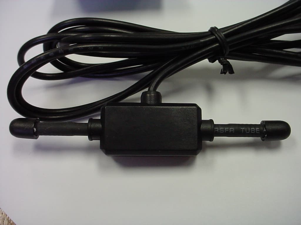
QPI-RFMODULE01
Mar 20, 2006Transmitter Module
Equipment Class
DSS - Part 15 Spread Spectrum Transmitter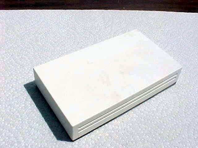
QPISLROOMTMP01
Jul 28, 2004Sensor Link Room Temperature Transmitter
Equipment Class
DXX - Part 15 Low Power Communication Device Transmitter