QQ6-XML02CodeXML M3 Bluetooth Modem
Code Corporation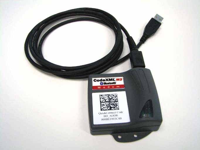
Click to zoom
Application Details
- Equipment Class
- DSS - Part 15 Spread Spectrum Transmitter
- Date of Grant
- Nov 14, 2007
- Application Purpose
- Original Equipment
- Date of Application
- Nov 14, 2007
- Equipment Note
- CodeXML M3 Bluetooth Modem
- Frequency Range
- 2402.00000000 - 2480.00000000
- Company
- Code Corporation
- Country
- United States
Documents & Files
Document Text
Text extracted from the exhibit documents filed with the FCC. Open a document above to read the original.
Users Manual
English (Default) Universal French German 2 C003996_01_CodeXML_M3_Modem_Quickstart C003996_01_CodeXML_M3_Modem_Quickstart 3 CodeXML M3 Bluetooth® Modem Installation with USB Cable Figure 3 Cable Installation Attach the end of the USB cable to the CodeXML M3 Bluetooth® Modem (Figure 2). Connect the USB connector to the host computer (Figure 3). Once connected the modem’s blue LED light will turn on. Figure 2 Establish Mode Scan the USB Mode code (M708_01-right). You are ready to begin reading bar codes and transmitting decoded data to the host computer. USB Cable installed to CodeXML M3 Bluetooth® Modem USB Mode Scan the QuickConnect Code on the label of the CodeXML M3 Bluetooth® Modem using the Code reader with which you wish to establish a paired connection to a host computer. The reader and host computer should easily connect within 60 seconds. The Code reader will beep once and flash both LEDs green as confirmation. If the reader and computer do not connect, the reader will beep three times in rapid succession and flash red LEDs. VVVVvvvvCKP BaudString: VVVV 4 digit firmware version (MSP430 firmware version) vvvv 4 digit firmware version (TUSB firmware version) C 1 digit comm mode: 1=RS-232, 2=Wand Emul., 3=USB KBD K Keyboard Map, same as reader host ICD setting 0x2d P 1 digit packet protocol: 0=Raw, 1=SPX packet, 2=Code Reader packet, 4=Encrypted Packet Format, 5= Protocol Version (AES) BaudString spx: Baud:DataBitsParityStopbits For All Readers: Scan to View Firmware Version Non-printable ASCII Keyboard (Crtl + character) Japanese Non-printable ASCII Keyboard (No Leading 0) The CodeXML Modem has been tested for compliance with FCC regulations and was found to be compliant with all applicable FCC Rules and Regulations. FCC ID#: QQ6-XML02 Model #: BTHDG-M3-RO-CX This equipment has been tested and found to comply with the limits for a Class B digital device, pursuant to Part 15 of the FCC Rules. These limits are designed to provide reasonable protection against harmful interference in a residential installation. This equipment generates, uses, and can radiate radio frequency energy and, if not installed and used in accordance with the instructions, may cause harmful interference to radio communications. However, there is no guarantee that interference will not occur in a particular installation. If this equipment does cause harmful interference to radio or television reception, which can be determined by turning the equipment off and on, the user is encouraged to try to correct the interference by one or more of the following measures: - Reorient or relocate the receiving antenna. - Increase the separation between the equipment and receiver. - Connect the equipment into an outlet on a circuit different from that to which the receiver is connected. - Consult the dealer or an experienced radio/TV technician for help. Any changes made by the user not approved by Code Corporation can void the user’s authority to operate the equipment. To satisfy FCC RF exposure requirements for mobile transmitting devices, a separation of 20 cm or more should be maintained between the antenna of this device and persons during device operation. To ensure compliance, operations at closer than this distance are not recommended. The antenna used for this transmitter must not be co-located in conjunction with any other antenna or transmitter. CodeXML M3 Bluetooth® Modem Important Note: Connecting with QuickConnect Code See instructions on page 3 for establishing a paired connection between the modem and the host computer. Keyboard Input (USB) The modem is defaulted to English language keyboards. If you need to communicate in a different language requiring a change in keyboard settings, please scan the appropriate code below: Connecting with QuickConnect Code (for all cable types): Modem Firmware Version Output & Values (for reference only): Quickstart Guide 4 C003996_01_CodeXML_M3_Modem_Quickstart CodeXML M3 Bluetooth® Modem - Multiple Interface Unit (MIU) C003996_01_CodeXML_M3_Modem_Quickstart 1 CodeXML M3 Blueooth® Modem Installation with RS232 The CodeXML M3 Bluetooth® MIU Modem is an external modem designed to be connected to the host computer in use with a Code reader (CR2 or CR3). The Modem enables a reader to wirelessly transmit captured and decoded data to its host computer. The Modem can accommodate cabled attachment with two connector types (Figure 1). Figure 1 The CodeXML M3 Bluetooth® Modem is ‘plug & play.’ You simply plug- in the Modem and start transmitting data from Code readers without downloading any drivers or software. The Modem can receive Bluetooth signals from up to 300 feet (100 meters) away. For assistance, contact Code Technical Support at: (801) 495 2200; or by email: [email protected] Figure 7Figure 8 Figure 9 Figure 10 RS-232 Cable (Left) - CodeXML M3 Bluetooth® Modem (Center) - Power Supply (Right) RS-232 Mode CodeXML M3 Bluetooth®Modem MIU Change Baud Rate Settings: Scan the appropriate code below: Note: These codes only affect Baud Rate for the modem and do not affect any settings on Code Readers. 1200 2400 4800 9600 (Default) 19200 38400 57600 115200 Default Modem settings: Baud Rate: 9600 Stop Bits: 8 Parity: None Stop Bits: 1 Hardware: None Establish Mode Scan the RS-232 Mode code (M661_01-right). You are ready to begin reading bar codes and transmitting decoded data to a host computer with any open software application that accepts data from RS-232/Serial input Connecting with QuickConnect Code See Page 2 for instructions to establish a paired connection between the Modem and the host computer. Cable Installation Attach the end of the RS-232 cable (pictured below) to the CodeXML M3 Bluetooth Modem (Figure 7). Connect the RS-232 adapter to the back of your computer (Figure 8). Connect the RS-232 cable to the power supply (Figure 9). Plug the power supply into a wall socket (Figure 10). Once connected the Modem’s blue LED light will turn on.
External Photos
External Photos
ID Label/Location Info
XML MODEM LABEL REFERENCE DRAWING C003688 (LABEL 8) MFG#: BTHDG- M2_01 Bluetooth Class: Class 1 Serial #: R0000000 Designed and assembled in the USA. Pat. Pending FCC ID# QQ6-XML02
Internal Photos
Top Side of PCB Bottom Side of PCB Top Side of PCB with RF Shield Removed
RF Exposure Info
Code Corporation FCC ID Number QQ6-XML02 Model Number BTHDG-M3-R0-CX RF Exposure Evaluation Report Per 47 CFR 15.247 (b)(4), the EUT meets the requirement that it be operated in a manner that ensures that the public is not exposed to radio frequency energy levels in excess of the Commission’s guidelines (ref. CFR 1.1307, 1.130, and 2.1093. See also OET Bulletin 65, Supplement C). The EUT is considered a mobile transmitter per 47 CFR 2.1093. The EUT will be installed and used 20 cm from the human body. The MPE estimates are as follows: The EUT is a mobile device. 47 CFR 2.1093 defines the maximum permissible exposure (MPE) to the body for the general population as 4W/kg as averaged over any 10 grams of tissue in the shape of a cube. This translates into a limit of 40mW for any 10 grams of tissue in the shape of a cube. The maximum power output of the EUT is 33.1 mW. The worst-case duty factor of the transmitter is 5/6. This occurs when the following sequence is repeated: The EUT transmits for 5 625us time slots The EUT receives for 1 625 us time slots The applicable duty cycle factor is 5/6. Applying the worst-case absorption by the user as well as the duty cycle factor of 5/6 to the power output of the EUT yields an absorption value of 27.583mW (33.1mW x 5/6 = 27.583 mW). If all of the absorbed energy were distributed in 10 grams of tissue in the shape of a cube then resulting power density would still fall below the limit of 40 mW for any 10 grams of tissue in the shape of a cube.
Test Report
COMMUNICATION CERTIFICATION LABORATORY 1940 West Alexander Street Salt Lake City, UT 84119 801-972-6146 Test Report Certification Test Of: CodeXML Modem BTHDG-M3-R0-CX FCC ID: QQ6-XML02 Test Specification: FCC PART 15, Subpart C Test Report Serial No: 871 Applicant: The Code Corporation 11814 South Election Road, Suite 200 Draper, UT 84020 Dates of Test: June 20 & 21, 2007 August 21, 2007 Issue Date: September 26, 2007 Accredited Testing Laboratory By: NVLAP Lab Code 100272-0 COMMUNICATION CERTIFICATION LABORATORY TEST REPORT: 871 FCC ID: QQ6-XML02 Page 2 of 43 CERTIFICATION OF ENGINEERING REPORT This report has been prepared by Communication Certification Laboratory to document compliance of the device described below with the requirements of Federal Communications Commission (FCC) Part 15, Subpart C. This report may be reproduced in full. Partial reproduction may only be made with the written consent of the laboratory. The results in this report apply only to the sample tested. - Applicant: The Code Corporation - Manufacturer: The Code Corporation - Brand Name: The Code Corporation - Model Number: CodeXML Modem BTHDG-M3-R0-CX - FCC ID Number: QQ6-XML02 On this 26 th day of September 2007, I, individually, and for Communication Certification Laboratory, certify that the statements made in this engineering report are true, complete, and correct to the best of my knowledge, and are made in good faith. Although NVLAP has accredited the Communication Certification Laboratory EMC testing facilities, this report must not be used to claim product certification, approval, or endorsement by NVLAP, NIST, or any agency of the federal government. COMMUNICATION CERTIFICATION LABORATORY Tested by: Norman P. Hansen EMC Technician COMMUNICATION CERTIFICATION LABORATORY TEST REPORT: 871 FCC ID: QQ6-XML02 Page 3 of 43 TABLE OF CONTENTS PAGE SECTION 1.0 CLIENT INFORMATION.................................4 SECTION 2.0 EQUIPMENT UNDER TEST (EUT) ..........................5 SECTION 3.0 TEST SPECIFICATION, METHODS & PROCEDURES ...........7 SECTION 4.0 OPERATION OF EUT DURING TESTING ...................15 SECTION 5.0 SUMMARY OF TEST RESULTS...........................16 SECTION 6.0 MEASUREMENTS, EXAMINATIONS AND DERIVED RESULTS.....17 APPENDIX 1 TEST PROCEDURES AND TEST EQUIPMENT ..................32 APPENDIX 2 PHOTOGRAPHS.........................................37 COMMUNICATION CERTIFICATION LABORATORY TEST REPORT: 871 FCC ID: QQ6-XML02 Page 4 of 43 SECTION 1.0 CLIENT INFORMATION 1.1 Applicant: Company Name: The Code Corporation 11814 South Election Road, Suite 200 Draper, UT 84020 Contact Name: Ryan Hyde Title: VP of Engineering 1.2 Manufacturer: Company Name: The Code Corporation 11814 South Election Road, Suite 200 Draper, UT 84020 Contact Name: Ryan Hyde Title: VP of Engineering COMMUNICATION CERTIFICATION LABORATORY TEST REPORT: 871 FCC ID: QQ6-XML02 Page 5 of 43 SECTION 2.0 EQUIPMENT UNDER TEST (EUT) 2.1 Identification of EUT: Brand Name: The Code Corporation Model Number: CodeXML Modem BTHDG-M3-R0-CX Serial Number: None Options Fitted: N/A 2.2 Description of EUT: The Radio Modem CR2AG-R0-01-02 functions as a wireless serial or USB cable replacement. Data from the USB or serial cable is transmitted by the Bluetooth transceiver. Power for the Radio Modem CR2AG-R0-01-02 is provided over the USB cable or placed on the serial cable by an external 5 VDC power supply. This report covers the transmitter that is required to meet the requirements of FCC Part 15, Subpart C. The other digital circuitry is covered in separate testing and report. 2.3 EUT and Support Equipment: The FCC ID numbers for the EUT and support equipment used during the test are listed below: Brand Name Model Number Serial No. FCC ID Number Description Name of Interface Ports / Interface Cables BN: Code Corporation MN: Radio Modem CR2AG-R0-01-02 (Note 1) QQ6- XML02 Bluetooth to USB adapter See Section 2.4 BN: HP MN: Pavilion DoC Laptop Computer USB/USB cable (Note 2) Note: (1) EUT (2) Interface port connected to EUT (See Section 2.4) COMMUNICATION CERTIFICATION LABORATORY TEST REPORT: 871 FCC ID: QQ6-XML02 Page 6 of 43 The support equipment listed above was not modified in order to achieve compliance with this standard. 2.4 Interface Ports on EUT: Name of Port No. of Ports Fitted to EUT Cable Descriptions/Length USB 1 USB cable/1.5 meters 2.5 Modification Incorporated/Special Accessories on EUT: There were no modifications or special accessories required to comply with the specification. Signature: Typed Name: Ryan Hyde Title: VP of Engineering COMMUNICATION CERTIFICATION LABORATORY TEST REPORT: 871 FCC ID: QQ6-XML02 Page 7 of 43 SECTION 3.0 TEST SPECIFICATION, METHODS & PROCEDURES 3.1 Test Specification: Title: FCC PART 15, Subpart C (47 CFR 15) Purpose of Test: The tests were performed to demonstrate initial compliance for modular certification. 3.2 Requirements: 3.2.1 §15.203 Antenna Requirement An intentional radiator shall be designed to ensure that no antenna other than that furnished by the responsible party shall be used with the device. The use of a permanently attached antenna or of an antenna that uses a unique coupling to the intentional radiator shall be considered sufficient to comply with the provisions of this Section. The manufacturer may design the unit so that a broken antenna can be replaced by the user, but the use of a standard antenna jack or electrical connector is prohibited. This requirement does not apply to carrier current devices or to devices operated under the provisions of Sections 15.211, 15.213, 15.217, 15.219, or 15.221. Further, this requirement does not apply to intentional radiators that must be professionally installed, such as perimeter protection systems and some field disturbance sensors, or to other intentional radiators which, in accordance with Section 15.31(d), must be measured at the installation site. However, the installer shall be responsible for ensuring that the proper antenna is employed so…
Text truncated - open the document above for the full version.
Test Setup Photos
Front View Radiated Spurious Emission Worst Case Configuration Back View Radiated Spurious Emission Worst Case Configuration Front View Conducted Disturbance Worst Case Configuration Back View Conducted Disturbance Worst Case Configuration
Contact Information
Applicant
Ryan W Hoobler(Director of Engineering)
Test Firm
Nemko-CCL, IncThomas Jackson
Technical Specifications
| # | Rule Parts | Frequency Range | Power Output |
|---|---|---|---|
| 1 | 15C | 2.40 GHz - 2.48 GHz | 33.10 mW |
Other Applications from Code Corporation
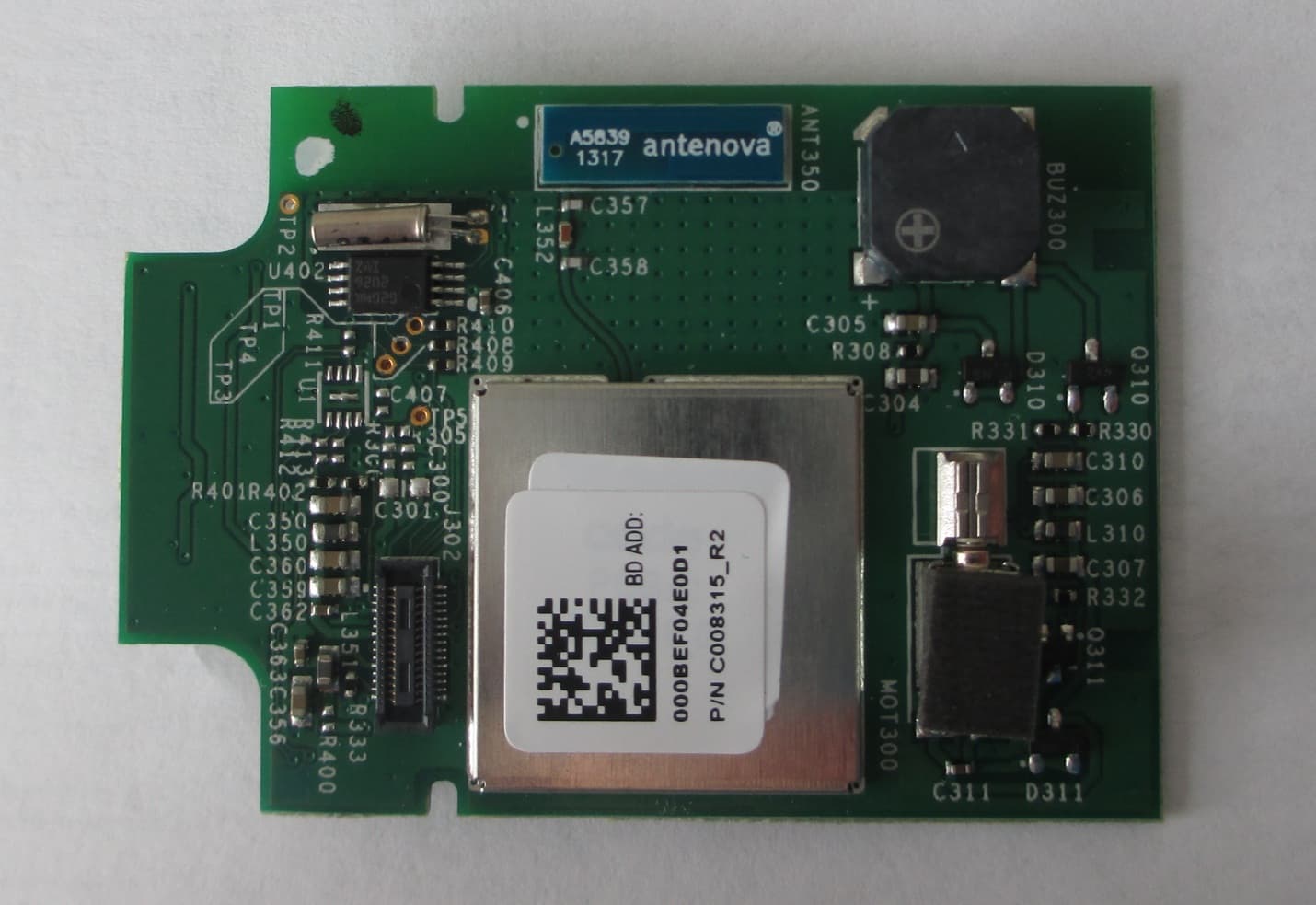
QQ6-BTR12
Dec 18, 2013BLUETOOTH MODULE
Equipment Class
DSS - Part 15 Spread Spectrum Transmitter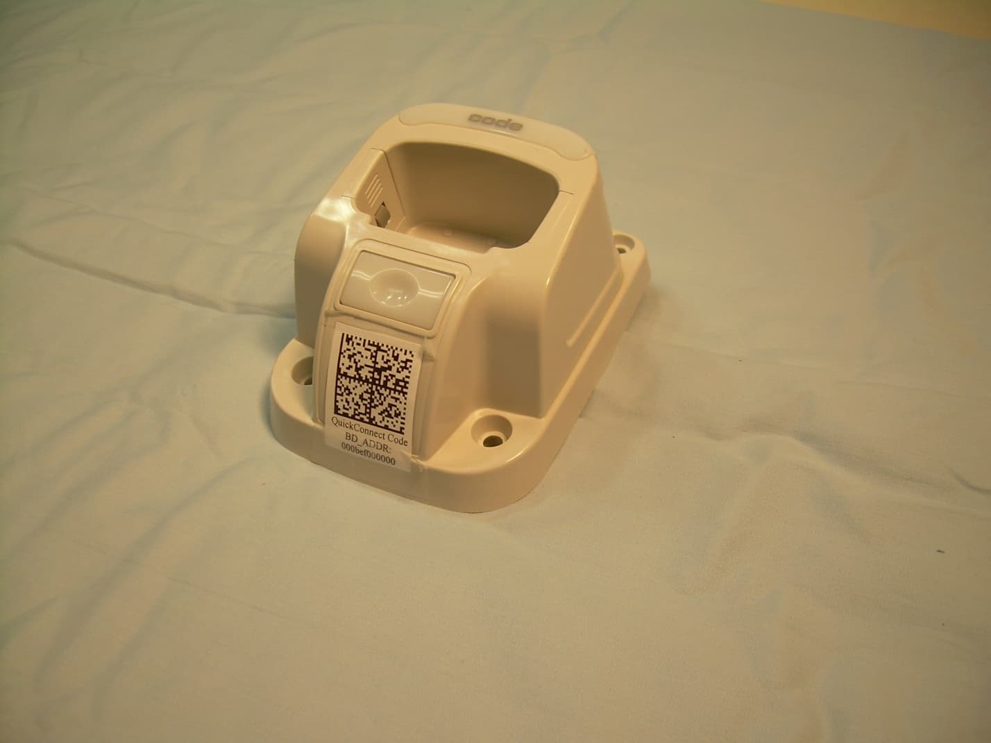
QQ6-BTC02
Dec 05, 2013CHARGER WITH BLUETOOTH TRANSCEIVER
Equipment Class
DSS - Part 15 Spread Spectrum Transmitter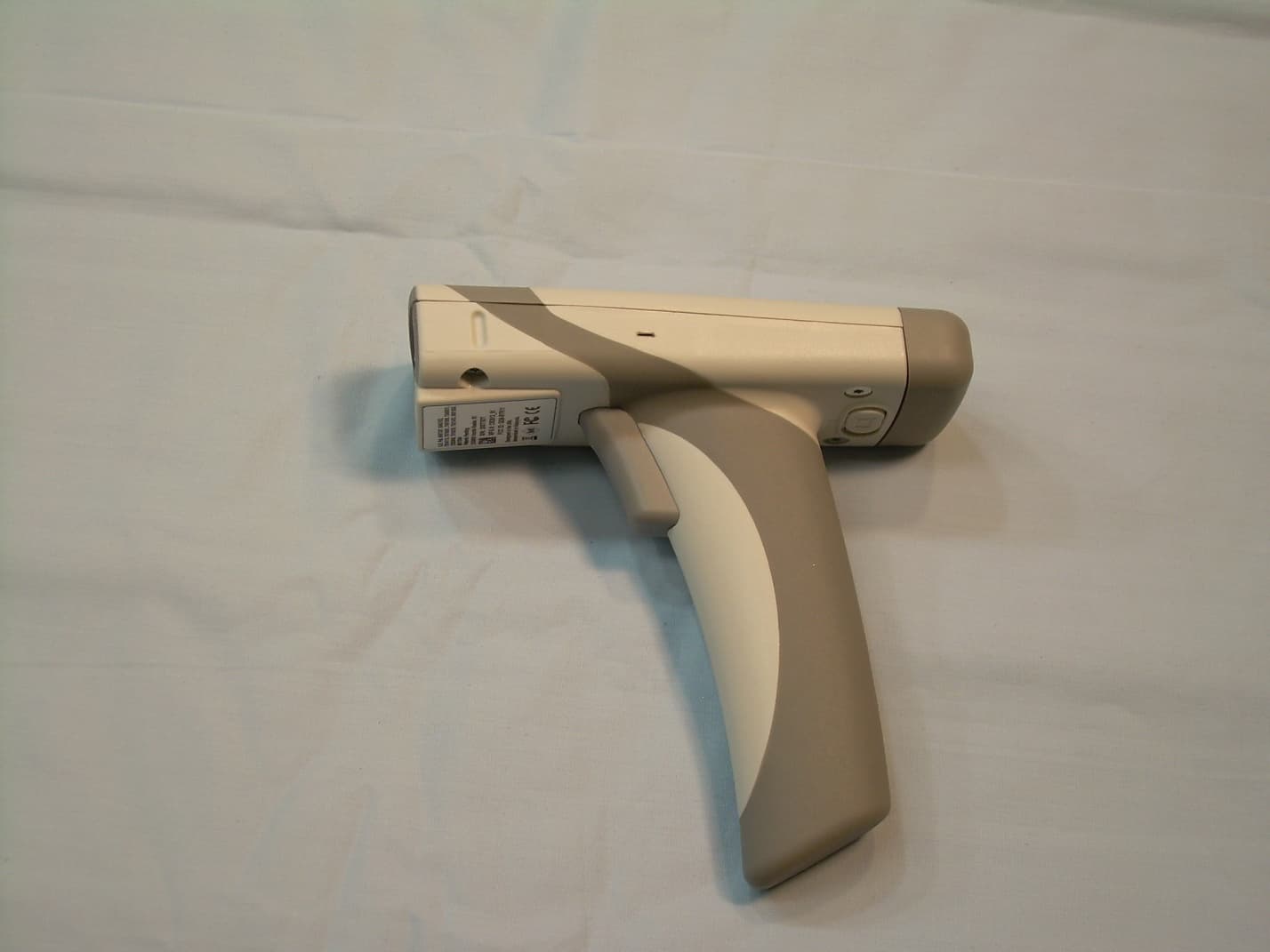
QQ6-BTR11
Feb 13, 2013BAR CODE READER
Equipment Class
DSS - Part 15 Spread Spectrum Transmitter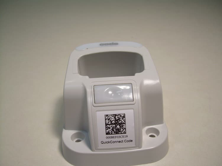
QQ6-BTC01
Feb 12, 2013CHARGING STATION WITH BLUETOOTH
Equipment Class
DSS - Part 15 Spread Spectrum Transmitter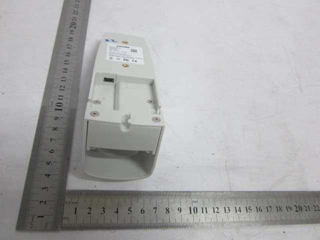
QQ6-RMS02
Apr 26, 2012ECS-RMS
Equipment Class
DSS - Part 15 Spread Spectrum Transmitter