QQL-R1902GGSM 850/1900 Data Modems
Sierra Wireless, ULC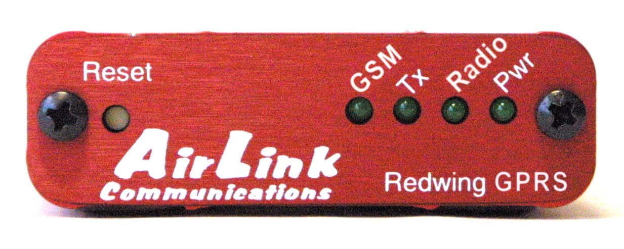
Click to zoom
Application Details
- Equipment Class
- PCB - PCS Licensed Transmitter
- Date of Grant
- Nov 04, 2003
- Application Purpose
- Original Equipment
- Date of Application
- Nov 04, 2003
- Equipment Note
- GSM 850/1900 Data Modems
- Frequency Range
- 1850.20000000 - 1909.80000000
- Company
- Sierra Wireless, ULC
- Country
- Canada
Documents & Files
Document Text
Text extracted from the exhibit documents filed with the FCC. Open a document above to read the original.
Users Manual
R R a a v v e e n n G G P P R R S S User Guide Version 1.08 AirLink Communications, Inc. September 29, 2003 AirLink Communications Information in this document is subject to change without notic © Copyright AirLink Communications, Inc, 1993-2003. All rights reserved. Please send comments to: email: [email protected] Fax: 510-226-4299 Phone: 510-226-4200 Post: AirLink Communications, Inc. Attention: Technical Publications Dept. 472 Kato Terrace Fremont, CA 94539 Important Notice Because of the nature of wireless communications, transmission and reception of data can never be guaranteed. Data may be delayed, corrupted (i.e., have errors) or be totally lost. Although significant delays or losses of data are rare when wireless devices such as the AirLink Communications modem are used in a normal manner with a well-constructed network, the AirLink modem should not be used in situations where failure to transmit or receive data could result in damage of any kind to the user or any other party, including but not limited to personal injury, death, or loss of property. AirLink Communications, Inc., accepts no responsibility for damages of any kind resulting from delays or errors in data transmitted or received using the AirLink Communications modem, or for failure of the AirLink Communications modem to transmit or receive such data. Safety and Hazards Do not operate the AirLink Communications modem in areas where blasting is in progress, where explosive atmospheres may be present, near medical equipment, near life support equipment, or any equipment which may be susceptible to any form of radio interference. In such areas, the AirLink Communications modem MUST BE POWERED OFF. The AirLink Communications modem can transmit signals that could interfere with this equipment. Do not operate the AirLink Communications modem in any aircraft, whether the aircraft is on the ground or in flight. In aircraft, the AirLink Communications modem MUST BE POWERED OFF. When operating, the AirLink Communications modem can transmit signals that could interfere with various onboard systems. The driver or operator of any vehicle should not operate the AirLink Communications modem while in control of a vehicle. Doing so will detract from the driver or operator's control and operation of that vehicle. In some states and provinces, operating such communications devices while in control of a vehicle is an offence. Limitation of Liability The information in this manual is subject to change without notice and does not represent a commitment on the part of AirLink Communications, Inc. AIRLINK COMMUNICATIONS, INC. SPECIFICALLY DISCLAIMS LIABILITY FOR ANY AND ALL DIRECT, INDIRECT, SPECIAL, GENERAL, INCIDENTAL, CONSEQUENTIAL, PUNITIVE OR EXEMPLARY DAMAGES INCLUDING, BUT NOT LIMITED TO, LOSS OF PROFITS OR REVENUE OR ANTICIPATED PROFITS OR REVENUE ARISING OUT OF THE USE OR INABILITY TO USE ANY AIRLINK COMMUNICATIONS, INC. PRODUCT, EVEN IF AIRLINK COMMUNICATIONS, INC. HAS BEEN ADVISED OF THE POSSIBILITY OF SUCH DAMAGES OR THEY ARE FORESEEABLE OR FOR CLAIMS BY ANY THIRD PARTY. Raven GPRS User Guide Table of Contents 1. Introduction ..................................................................................... 5 1.1 Raven Product Overview ............................................................................... 6 2. Network Connection ...................................................................... 7 2.1 Internet (TCP/IP) Connections via GPRS .................................................... 7 2.2 Data Connections........................................................................................... 7 3. Raven and PinPoint GPRS Configuration ................................ 9 3.1 Local Configuration ....................................................................................... 9 3.2 Modem Activation ........................................................................................ 11 3.2.1 SIM Check 12 3.2.2 PDP Context 12 3.3 Remote Configuration.................................................................................. 13 4. Windows Dial-Up Networking Setup ........................................ 14 4.1 Add Windows Modem Driver ...................................................................... 14 4.1.1 Setup Modem 14 4.1.2 Add Modem Driver 14 4.2 Windows Dial-Up Networking (PPP) Configuration ................................. 17 4.3 Making a GPRS Data Connection............................................................... 25 5. Dynamic IP Addresses ................................................................. 26 5.1 IPManager and Dynamic DNS Updates..................................................... 27 5.2 Using Names in the Modem, Domain Name Resolving............................. 27 6. Serial Communication Modes .................................................... 29 6.1 AT Mode ....................................................................................................... 30 6.2 PPP Mode ..................................................................................................... 30 6.3 PassThru Mode ............................................................................................ 31 6.4 UDP PAD Mode ........................................................................................... 31 6.4.1 UDP Auto Answer 32 6.4.2 Reliable UDP 32 6.4.3 Multicast UDP [Raven Only Feature] 33 6.5 TCP PAD Mode ............................................................................................ 33 6.6 TCP Auto Answer ........................................................................................ 34 6.7 Hybrid Modes ............................................................................................... 34 6.8 SLIP Mode.................................................................................................... 35 6.9 Modbus/BSAP Configuration [Raven Only Feature] ................................. 35 6.9.1 Configuring the Pol…
Text truncated - open the document above for the full version.
Users Manual
P P i i n n P P o o i i n n t t G G P P R R S S User Guide Version 1.08 AirLink Communications, Inc. September 27, 2003 AirLink Communications Information in this document is subject to change without notic © Copyright AirLink Communications, Inc, 1993-2003. All rights reserved. Please send comments to: email: [email protected] Fax: 510-226-4299 Phone: 510-226-4200 Post: AirLink Communications, Inc. Attention: Technical Publications Dept. 472 Kato Terrace Fremont, CA 94539 Important Notice Because of the nature of wireless communications, transmission and reception of data can never be guaranteed. Data may be delayed, corrupted (i.e., have errors) or be totally lost. Although significant delays or losses of data are rare when wireless devices such as the AirLink Communications modem are used in a normal manner with a well-constructed network, the AirLink modem should not be used in situations where failure to transmit or receive data could result in damage of any kind to the user or any other party, including but not limited to personal injury, death, or loss of property. AirLink Communications, Inc., accepts no responsibility for damages of any kind resulting from delays or errors in data transmitted or received using the AirLink Communications modem, or for failure of the AirLink Communications modem to transmit or receive such data. Safety and Hazards Do not operate the AirLink Communications modem in areas where blasting is in progress, where explosive atmospheres may be present, near medical equipment, near life support equipment, or any equipment which may be susceptible to any form of radio interference. In such areas, the AirLink Communications modem MUST BE POWERED OFF. The AirLink Communications modem can transmit signals that could interfere with this equipment. Do not operate the AirLink Communications modem in any aircraft, whether the aircraft is on the ground or in flight. In aircraft, the AirLink Communications modem MUST BE POWERED OFF. When operating, the AirLink Communications modem can transmit signals that could interfere with various onboard systems. The driver or operator of any vehicle should not operate the AirLink Communications modem while in control of a vehicle. Doing so will detract from the driver or operator's control and operation of that vehicle. In some states and provinces, operating such communications devices while in control of a vehicle is an offence. Limitation of Liability The information in this manual is subject to change without notice and does not represent a commitment on the part of AirLink Communications, Inc. AIRLINK COMMUNICATIONS, INC. SPECIFICALLY DISCLAIMS LIABILITY FOR ANY AND ALL DIRECT, INDIRECT, SPECIAL, GENERAL, INCIDENTAL, CONSEQUENTIAL, PUNITIVE OR EXEMPLARY DAMAGES INCLUDING, BUT NOT LIMITED TO, LOSS OF PROFITS OR REVENUE OR ANTICIPATED PROFITS OR REVENUE ARISING OUT OF THE USE OR INABILITY TO USE ANY AIRLINK COMMUNICATIONS, INC. PRODUCT, EVEN IF AIRLINK COMMUNICATIONS, INC. HAS BEEN ADVISED OF THE POSSIBILITY OF SUCH DAMAGES OR THEY ARE FORESEEABLE OR FOR CLAIMS BY ANY THIRD PARTY. PinPoint GPRS Table of Contents 1. Introduction ..................................................................................... 1 1.1 PinPoint Product Overview ........................................................................... 2 2. Network Connection ...................................................................... 3 2.1 Internet (TCP/IP) Connections via GPRS .................................................... 3 2.2 Data Connections........................................................................................... 3 3. Raven and PinPoint GPRS Configuration ................................ 5 3.1 Local Configuration ....................................................................................... 5 3.2 Modem Activation .......................................................................................... 7 3.2.1 SIM Check 8 3.2.2 PDP Context 8 3.3 Remote Configuration.................................................................................... 9 4. Windows Dial-Up Networking Setup ........................................ 10 4.1 Add Windows Modem Driver ...................................................................... 10 4.1.1 Setup Modem 10 4.1.2 Add Modem Driver 10 4.2 Windows Dial-Up Networking (PPP) Configuration ................................. 13 4.3 Making a GPRS Data Connection............................................................... 20 5. Dynamic IP Addresses ................................................................. 21 5.1 IPManager and Dynamic DNS Updates..................................................... 22 5.2 Using Names in the Modem, Domain Name Resolving............................. 22 6. Serial Communication Modes .................................................... 23 6.1 AT Mode ....................................................................................................... 24 6.2 PPP Mode ..................................................................................................... 24 6.3 PassThru Mode ............................................................................................ 25 6.4 UDP PAD Mode ........................................................................................... 25 6.4.1 UDP Auto Answer 26 6.4.2 Reliable UDP 26 6.4.3 Multicast UDP [Raven Only Feature] 26 6.5 TCP PAD Mode ............................................................................................ 27 6.6 TCP Auto Answer ........................................................................................ 28 6.7 Hybrid Modes ............................................................................................... 28 6.8 SLIP Mode.................................................................................................... 28 6.9 Modbus/BSAP Configuration [Raven Only Feature] ................................. 28 6.9.1 Configuring the …
Text truncated - open the document above for the full version.
Users Manual
R R e e d d w w i i n n g g G G P P R R S S User Guide Version 1.08 AirLink Communications, Inc. September 29, 2003 AirLink Communications Information in this document is subject to change without notic © Copyright AirLink Communications, Inc, 1993-2003. All rights reserved. Please send comments to: email: [email protected] Fax: 510-226-4299 Phone: 510-226-4200 Post: AirLink Communications, Inc. Attention: Technical Publications Dept. 472 Kato Terrace Fremont, CA 94539 Important Notice Because of the nature of wireless communications, transmission and reception of data can never be guaranteed. Data may be delayed, corrupted (i.e., have errors) or be totally lost. Although significant delays or losses of data are rare when wireless devices such as the AirLink Communications modem are used in a normal manner with a well-constructed network, the AirLink modem should not be used in situations where failure to transmit or receive data could result in damage of any kind to the user or any other party, including but not limited to personal injury, death, or loss of property. AirLink Communications, Inc., accepts no responsibility for damages of any kind resulting from delays or errors in data transmitted or received using the AirLink Communications modem, or for failure of the AirLink Communications modem to transmit or receive such data. Safety and Hazards Do not operate the AirLink Communications modem in areas where blasting is in progress, where explosive atmospheres may be present, near medical equipment, near life support equipment, or any equipment which may be susceptible to any form of radio interference. In such areas, the AirLink Communications modem MUST BE POWERED OFF. The AirLink Communications modem can transmit signals that could interfere with this equipment. Do not operate the AirLink Communications modem in any aircraft, whether the aircraft is on the ground or in flight. In aircraft, the AirLink Communications modem MUST BE POWERED OFF. When operating, the AirLink Communications modem can transmit signals that could interfere with various onboard systems. The driver or operator of any vehicle should not operate the AirLink Communications modem while in control of a vehicle. Doing so will detract from the driver or operator's control and operation of that vehicle. In some states and provinces, operating such communications devices while in control of a vehicle is an offence. Limitation of Liability The information in this manual is subject to change without notice and does not represent a commitment on the part of AirLink Communications, Inc. AIRLINK COMMUNICATIONS, INC. SPECIFICALLY DISCLAIMS LIABILITY FOR ANY AND ALL DIRECT, INDIRECT, SPECIAL, GENERAL, INCIDENTAL, CONSEQUENTIAL, PUNITIVE OR EXEMPLARY DAMAGES INCLUDING, BUT NOT LIMITED TO, LOSS OF PROFITS OR REVENUE OR ANTICIPATED PROFITS OR REVENUE ARISING OUT OF THE USE OR INABILITY TO USE ANY AIRLINK COMMUNICATIONS, INC. PRODUCT, EVEN IF AIRLINK COMMUNICATIONS, INC. HAS BEEN ADVISED OF THE POSSIBILITY OF SUCH DAMAGES OR THEY ARE FORESEEABLE OR FOR CLAIMS BY ANY THIRD PARTY. Redwing GPRS User Guide Table of Contents 1. Introduction ..................................................................................... 1 1.1 Redwing Product Overview ........................................................................... 2 2. Redwing Network Connection ..................................................... 3 2.1 Internet (TCP/IP) Connections via GPRS .................................................... 3 3. Redwing GPRS Configuration ..................................................... 4 3.1 Configuration Procedure ............................................................................... 4 3.2 Modem Activation .......................................................................................... 6 3.2.1 SIM Check 7 3.2.2 PDP Context 7 4. Using AT Commands ...................................................................... 9 4.1 Redwing GPRS Specific AT Commands ..................................................... 10 4.2 Redwing AT Command Summary .............................................................. 13 4.3 Redwing SMS Command Summary ........................................................... 15 4.4 Redwing GPRS Commands ......................................................................... 16 4.5 RIM Specific AT Commands ....................................................................... 16 5. Redwing GPRS Technical Specifications ................................ 17 5.1 Physical Characteristics .............................................................................. 17 5.2 Power Specifications .................................................................................... 17 5.3 Environmental ............................................................................................. 17 5.4 RF Features ................................................................................................. 17 5.5 Status LED Display ..................................................................................... 18 5.6 Application Interface Features ................................................................... 18 Redwing GPRS User Guide 1. Introduction The GSM/GPRS wireless network combines the world’s leading wireless standard— the Global System for Mobile Communications (GSM)—with fast, packet-switched access to data networks such as the Internet. Providing this fast access is the General Packet Radio Service (GPRS). The AirLink GPRS modems are designed to operate in GSM/GPRS networks. Two data services are available in the GSM/GPRS networks: GPRS, a packet switched connection, and SMS, a short message service.. GPRS GPRS is an IP-based service that offers fast, packet-switched access to data networks such as the Internet. It is a mobile service that improves the peak-time capacity of a GSM network. GPRS gives packet-switched access over GSM to external data networks with high …
Text truncated - open the document above for the full version.
Attestation Statements
AirLink Communications, Inc. 472 Kato Terrace Fremont, CA 94539 Phone: 510-226-4200 Fax: 510-226-4299 Date: August 22, 2003 Federal Communications Commission Authorization & Evaluation Division 7345 Oakland Mills Road Columbia, Maryland 21046 Gentlemen: We the undersigned, hereby authorize CETECOM Inc. (411 Dixon Landing Road, Milpitas, CA 95035, Tel.408 586 6214) to act on our behalf in all manners relating to application for equipment authorization, including signing of all documents relating to these matters. Any and all acts carried out by CETECOM Inc., on our behalf shall have the same effect as acts of our own. The authorization from AirLink Communications, Inc. is valid until further notice from us. This is to advise that we are in full compliance with the Anti-Drug Abuse Act. The Applicant is not subject to a denial of federal benefits pursuant to Section 5301 of the Anti- Drug Abuse Act of 1988, 21 USC 862, and no party to the application is subject to a denial of federal benefits pursuant to that section. AirLink Communications, Inc. Jim Baichtal Vice President of Engineering AirLink Communications AirLink AirLink Communications, Inc. September 7, 2002 Page 2 Confidential
Attestation Statements
G G 3 3 1 1 1 1 0 0 G G 3 3 2 2 1 1 0 0 G G 3 3 3 3 1 1 0 0 Feature Comparison Version 1.0 AirLink Communications, Inc. October 14, 2003 AirLink Communications Information in this document is subject to change without notice. © Copyright AirLink Communications, Inc, 1993-2003. All rights reserved. Please send comments to: email: [email protected] Fax: 510-226-4299 Phone: 510-226-4200 Post: AirLink Communications, Inc. Attention: Technical Publications Dept. 472 Kato Terrace Fremont, CA 94539 G3110 G3210 G3310 Feature Comparison Version 1.0 AirLink Communications, Inc. Page i October 14, 2003 Table of Contents 1 Introduction ..................................................................................... 1 2 Overview of Common Features.................................................... 1 2.1 Redwing Block Diagram ................................................................................ 2 2.2 Raven Block Diagram .................................................................................... 3 2.3 PinPoint Block Diagram ................................................................................ 4 2.4 RIM 1902G OEM Module .............................................................................. 5 2.5 Voltage Regulators......................................................................................... 5 2.6 Power Input Protection.................................................................................. 5 2.7 Serial Port Protection and Conversion ......................................................... 5 3 Raven and PinPoint Enhancements ........................................... 6 3.1 ALEOS Features ............................................................................................ 6 3.2 Real-Time Clock ............................................................................................. 6 3.3 Voltage Regulator Control............................................................................. 6 3.4 GPS Module in PinPoint................................................................................ 6 4 Network Operations ....................................................................... 7 4.1 Redwing .......................................................................................................... 7 4.2 Raven and PinPoint ....................................................................................... 8 AirLink Communications, Inc. Page 1 October 14, 2003 G3110 G3210 G3310 Feature Comparison 1 Introduction The Redwing [G3110], Raven [G3210], and PinPoint [G3310] GPRS modems are designed to operate in GPRS networks. The Redwing is intended to be used with intelligent devices that contain a TCP/IP protocol stack, and use the Redwing only as a GPRS network access device. The Raven and PinPoint modems add an ARM processor and a real-time clock which enhances the capabilities of these modems. The Raven can interface with a large number of different devices and provide the data communications functions necessary for the devices to operate over a GPRS network. The PinPoint contains the same functionality as the Raven, and adds a GPS module to provide location information. 2 Overview of Common Features The GPRS modems share a number of common hardware features. The AirLink GPRS modems use the RIM OEM module, the 1902G, to implement the GSM/GPRS modem functions. AirLink mounts all the components for the modems in rugged enclosures which provide physical and electrical protection, and a wide range power regulator. G3110 G3210 G3310 Feature Comparison Version 1.0 AirLink Communications, Inc. Page 2 October 14, 2003 The following block diagrams show the major hardware functions for each. 2.1 Redwing Block Diagram RIM 1902G GSM GPRS Modem DB9 Connector ESD Protection RS232 – TTL Signal Conversion Serial Port Power Input 10 – 28 VDC Protection and Voltage Monitor 3.6 VDC Voltage Regulator LED Status LEDs Antenna Connector G3110 G3210 G3310 Feature Comparison Version 1.0 AirLink Communications, Inc. Page 3 October 14, 2003 2.2 Raven Block Diagram Serial Port DB9 Connector ESD Protection RS232 Signal Conversion Power Input 10 – 28 VDC Protection and Voltage Monitor 3.3, 3.6 DC Voltage Regulators Status LEDs & Drivers RIM 1902G GSM GPRS Modem Modem Antenna Connector ARM Processor RTC Dual UART G3110 G3210 G3310 Feature Comparison Version 1.0 AirLink Communications, Inc. Page 4 October 14, 2003 2.3 PinPoint Block Diagram Serial Port DB9 Connector ESD Protection RS232 Signal Conversion Power Input 10 – 28 VDC Protection and Voltage Monitor 3.3, 3.6, 5.0 VDC Voltage Regulators Status LEDs & Drivers RIM 1902G GSM/GPRS Modem Modem Antenna Connector PS Antenna GPS Module Dual UART ARM Processor NVRAM RTC G3110 G3210 G3310 Feature Comparison Version 1.0 AirLink Communications, Inc. Page 5 October 14, 2003 2.4 RIM 1902G OEM Module RIM’s embedded OEM GPRS modem module, the 1902G, is used to provide the GSM/GPRS modem functions in the AirLink GPRS modems. 2.5 Voltage Regulators An efficient switching voltage regulator converts the 10 to 28 VDC input power to 3.6 VDC in the Redwing and 5.3 VDC in the Raven and PinPoint. A pair of linear voltage regulators regulates the 5.3 VDC to 3.3 and 3.6 VDC in the Raven and PinPoint. 2.6 Power Input Protection Power input over-current protection is provided by employing a 500 ma resettable PTC device that will open when the input current exceeds 500 ma. After a period of time, it will reset and conduct current again. A diode in the power input ground path protects against accidental reverse power connections. Current is blocked from flowing through the ground path to other external ground connections to the modem. Overvoltage protection is provided with a tranzorb connected across the power input lines. It will conduct the input voltage to ground if the input voltage exceeds 30V. A voltage monitor circuit will turn the voltage regulator on and off at levels sufficient to insure proper operation of th…
Text truncated - open the document above for the full version.
Cover Letter(s)
AirLink Communications, Inc. 472 Kato Terrace Fremont, CA 94539 Phone: 510-226-4200 Fax: 510-226-4299 October 3, 2003 Federal Communications Commission EQUIPMENT APPROVAL SERVICES P. O. Box 358315 Pittsburgh, PA 15251-5315 ATTN: Authorization & Evaluation Division PER: 47 CFR 0.457 and 0.459 RE: QQL-R1902G Pursuant to Sections 0.457(d)(1)(ii) and 0.459 of the Commission's Rules, the Applicant hereby requests confidential treatment of some of the information accompanying this Application as listed below, i.e. Schematics, Bills of materials, Theory of operation, Block Diagram, and the Tune-Up Procedure. These materials contain trade secrets and proprietary information not customarily released to the public and the public disclosure of these matters might be harmful to the Applicant and provide unjustified benefits to its competitors. The Applicant understands that pursuant to Rule 0.457(d)(1)(ii) disclosure of this Application and all accompanying documentation will not be made before the date of the Grant for this Application. Sincerely, AirLink Communications, Inc. Jim Baichtal Vice President of Engineering AirLink Communications
External Photos
Model: PinPoint GPRS Model Number: G3310 FCC ID: QQL-R1902G Front view Rear view Rear view Top view Bottom view Model: Redwing GPRS Model Number: G3110 FCC ID: QQL-R1902G Front view Rear view Top view Bottom view
ID Label/Location Info
AirLink Communications, Inc. 472 Kato Terrace Fremont, CA 94539 Phone: 510-226-4200 Fax: 510-226-4299 Date: August 22, 2003 Raven GPRS G3210 LABEL FOR 1-PART STATEMENT AirLink Communications, Inc. FCC ID: QQL-R1902G Model: G3210 IC: 4481A-R1902G Country Of Origin: USA This device complies with Part 15 of the FCC Rules. Operation is subject to the condition that this device does not cause harmful interference. Label Size: 1” high x 4” long Label Location: Centered on bottom of unit AirLink Communications
ID Label/Location Info
AirLink Communications, Inc. 472 Kato Terrace Fremont, CA 94539 Phone: 510-226-4200 Fax: 510-226-4299 Date: August 22, 2003 PinPoint GPRS G3310 LABEL FOR 1-PART STATEMENT AirLink Communications, Inc. FCC ID: QQL-R1902G Model: G3310 IC: 4481A-R1902G Country Of Origin: USA This device complies with Part 15 of the FCC Rules. Operation is subject to the condition that this device does not cause harmful interference. Label Size: 1” high x 4” long Label Location: Centered on bottom of unit AirLink Communications
ID Label/Location Info
AirLink Communications, Inc. 472 Kato Terrace Fremont, CA 94539 Phone: 510-226-4200 Fax: 510-226-4299 Date: August 22, 2003 Redwing GPRS G3110 LABEL FOR 1-PART STATEMENT AirLink Communications, Inc. FCC ID: QQL-R1902G Model: G3110 IC: 4481A-R1902G Country Of Origin: USA This device complies with Part 15 of the FCC Rules. Operation is subject to the condition that this device does not cause harmful interference. Label Size: 1” high x 4” long Label Location: Centered on bottom of unit AirLink Communications
Internal Photos
Model: PinPoint GPRS Model Number: G3310 FCC ID: QQL-R1902G PCB Bottom view with GSM Module PCB Bottom view without GSM Module Top view with GPS Top view without GPS GSM Module Top view GSM Module Bottom view Model: Raven GPRS Model Number: G3210 FCC ID: QQL-R1902G Top view with GSM Module Top view without GSM Module Bottom view GSM Module Top view GSM Module Bottom view Model: Redwing GPRS Model Number: G3110 FCC ID: QQL-R1902G PCB Top view PCB Bottom view
Operational Description
R R a a v v e e n n G G P P R R S S G G 3 3 2 2 1 1 0 0 Theory of Operation Version 1.0 AirLink Communications, Inc. Proprietary and Confidential July 18, 2003 AirLink Communications Information in this document is subject to change without notice. © Copyright AirLink Communications, Inc, 1993-2003. All rights reserved. Please send comments to: email: [email protected] Fax: 510-226-4299 Phone: 510-226-4200 Post: AirLink Communications, Inc. Attention: Technical Publications Dept. 472 Kato Terrace Fremont, CA 94539 Table of Contents 1 Introduction ..................................................................................... 1 2 Block Diagram ................................................................................. 2 3 Description ....................................................................................... 3 3.1 RIM 1902G Modem ........................................................................................ 3 3.2 Voltage Regulator Control............................................................................. 3 3.3 Power Input Protection.................................................................................. 3 3.4 Serial Port Protection and Conversion ......................................................... 3 3.5 LED Drivers ................................................................................................... 3 3.6 Modem Antenna Connector.............................…
Text truncated - open the document above for the full version.
Contact Information
Applicant
Ying Wang
Technical Contact
CETECOM Inc.Lothar Schmidt
[email protected]+1 408 586 6214
411 Dixon Landing Road · Milpitas, California · United States
Test Firm
Cetecom Inc.Lothar Schmidt
Technical Specifications
| # | Rule Parts | Frequency Range | Power Output | Emission | Tolerance |
|---|---|---|---|---|---|
| 2 | 24E | 1.85 GHz - 1.91 GHz | 903.00 mW | 300KGXW | 0.028 ppm |
Other Applications from Sierra Wireless, ULC
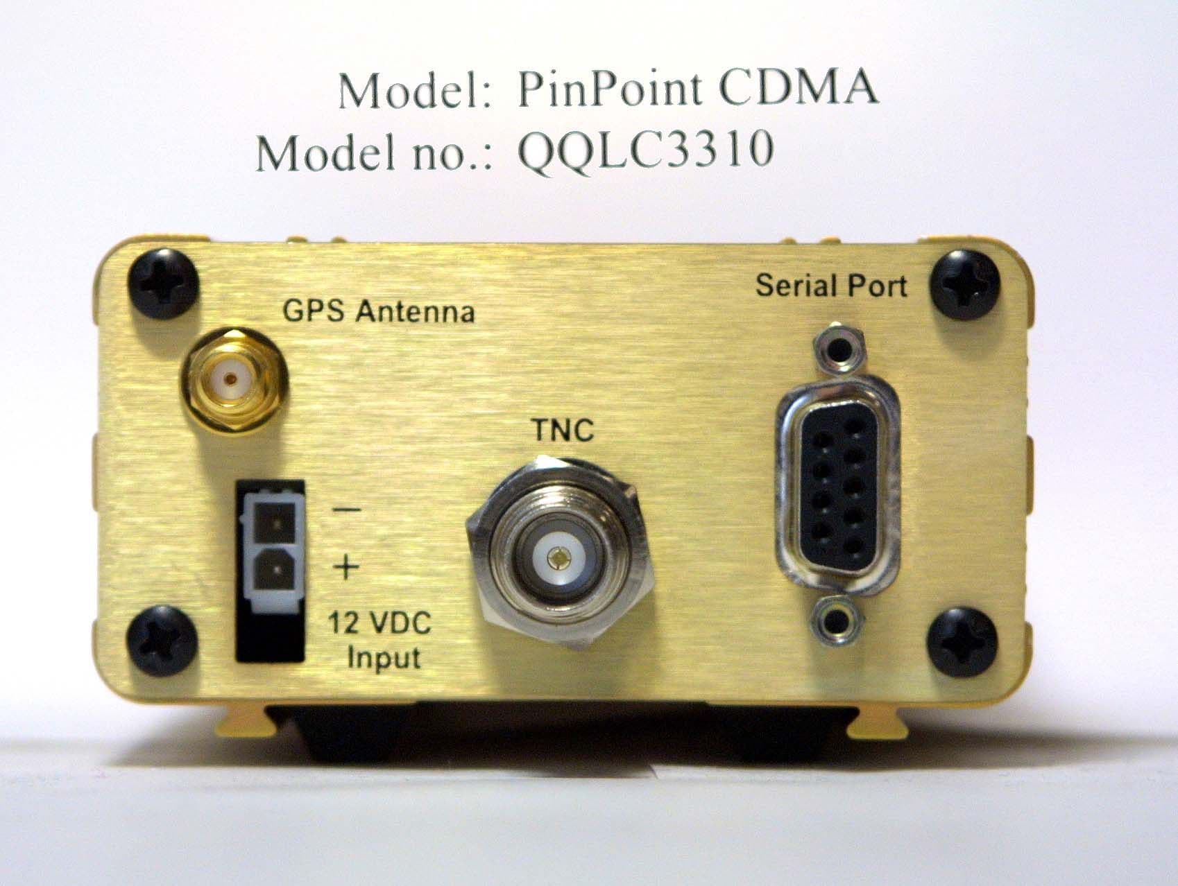
QQLC3310
Mar 09, 2003Dual Mode, Dual Channel Modem
Equipment Class
PCB - PCS Licensed Transmitter
QQLC3110
Dec 26, 2002Dual Mode, Dual Channel Modem
Equipment Class
PCB - PCS Licensed Transmitter