QQLC3110Dual Mode, Dual Channel Modem
Sierra Wireless, ULC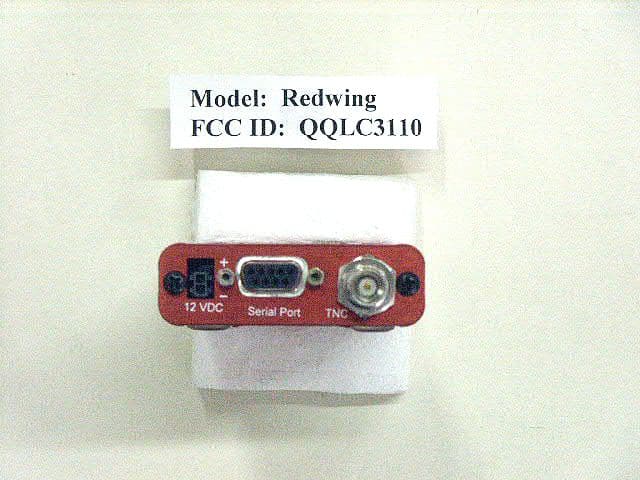
Click to zoom
Application Details
- Equipment Class
- PCB - PCS Licensed Transmitter
- Date of Grant
- Dec 26, 2002
- Application Purpose
- Original Equipment
- Date of Application
- Dec 26, 2002
- Equipment Note
- Dual Mode, Dual Channel Modem
- Frequency Range
- 825.00000000 - 848.00000000
- Company
- Sierra Wireless, ULC
- Country
- Canada
Documents & Files
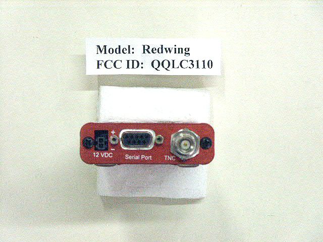
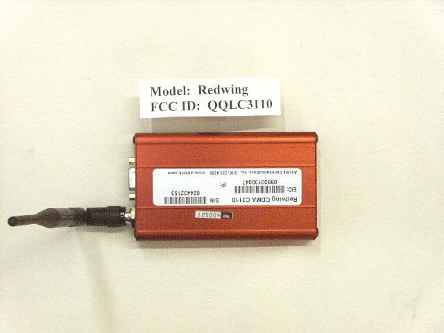
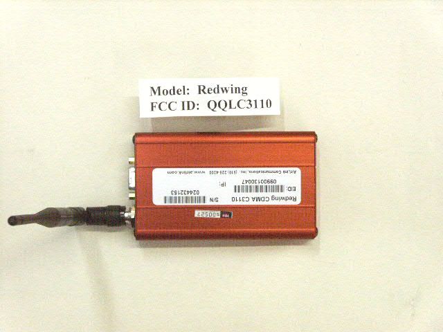
Document Text
Text extracted from the exhibit documents filed with the FCC. Open a document above to read the original.
Users Manual
R R e e d d w w i i n n g g C C D D M M A A User Guide Version 1.0 AirLink Communications, Inc. December 11, 2002 AirLink Communications Redwing CDMA User Guide Version 1.0 AirLink Communications, Inc. Page 1 December 11, 2002 Information in this document is subject to change without notice. © Copyright AirLink Communications, Inc, 1993-2002. All rights reserved. Please send comments to: email: [email protected] Fax: 510-226-4299 Phone: 510-226-4200 Post: AirLink Communications, Inc. Attention: Technical Publications Dept. 472 Kato Terrace Fremont, CA 94539 Preface AirLink Communications, Inc. Page i December 11, 2002 Important Notice Because of the nature of wireless communications, transmission and reception of data can never be guaranteed. Data may be delayed, corrupted (i.e., have errors) or be totally lost. Although significant delays or losses of data are rare when wireless devices such as the Sierra Wireless modem are used in a normal manner with a well- constructed network, the Sierra Wireless modem should not be used in situations where failure to transmit or receive data could result in damage of any kind to the user or any other party, including but not limited to personal injury, death, or loss of property. AirLink Communications, Inc., accepts no responsibility for damages of any kind resulting from delays or errors in data transmitted or received using the AirLink Communications modem, or for failure of the AirLink Communications modem to transmit or receive such data. Safety and Hazards Do not operate the AirLink Communications modem in areas where blasting is in progress, where explosive atmospheres may be present, near medical equipment, near life support equipment, or any equipment which may be susceptible to any form of radio interference. In such areas, the AirLink Communications modem MUST BE POWERED OFF. The AirLink Communications modem can transmit signals that could interfere with this equipment. Do not operate the AirLink Communications modem in any aircraft, whether the aircraft is on the ground or in flight. In aircraft, the AirLink Communications modem MUST BE POWERED OFF. When operating, the AirLink Communications modem can transmit signals that could interfere with various onboard systems. The driver or operator of any vehicle should not operate the AirLink Communications modem while in control of a vehicle. Doing so will detract from the driver or operator's control and operation of that vehicle. In some states and provinces, operating such communications devices while in control of a vehicle is an offence. Limitation of Liability The information in this manual is subject to change without notice and does not represent a commitment on the part of AirLink Communications, Inc. AIRLINK COMMUNICATIONS, INC. SPECIFICALLY DISCLAIMS LIABILITY FOR ANY AND ALL DIRECT, INDIRECT, SPECIAL, GENERAL, INCIDENTAL, CONSEQUENTIAL, PUNITIVE OR EXEMPLARY DAMAGES INCLUDING, BUT NOT LIMITED TO, LOSS OF PROFITS OR REVENUE OR ANTICIPATED PROFITS OR REVENUE ARISING OUT OF THE USE OR INABILITY TO USE ANY AIRLINK COMMUNICATIONS, INC. PRODUCT, EVEN IF AIRLINK COMMUNICATIONS, INC. HAS BEEN ADVISED OF THE POSSIBILITY OF SUCH DAMAGES OR THEY ARE FORESEEABLE OR FOR CLAIMS BY ANY THIRD PARTY. Redwing CDMA User Guide Version 1.0 AirLink Communications, Inc. Page i December 11, 2002 Table of Contents 1 Introduction ..................................................................................... 1 2 Product Overview ........................................................................... 3 2.1 Technical Overview........................................................................................ 3 2.1.1 Quick Look: 3 2.1.2 Physical Characteristics: 3 2.1.3 Power Specifications: 3 2.1.4 Environmental: 4 2.1.5 Local LED Display: 4 2.1.6 RF Features: 4 2.1.7 IS-95A Circuit-Switched Mode Features: 4 2.1.8 Short Message Service (SMS) Features: 4 2.1.9 Packet Mode Features (1xRTT): 4 2.1.10 Application Interface Features: 4 2.1.11 CDMA and Cellular Standards: 5 3 Network Connection Options ....................................................... 6 3.1 Internet (TCP/IP) Connections via 1xRTT ................................................... 6 3.2 Circuit-Switched CDMA Connections........................................................... 7 4 Windows 2000 Setup for 1xRTT Communications ................... 8 4.1 Windows 2000 Com Port Configuration ....................................................... 8 4.2 Windows 2000 Modem Configuration........................................................... 9 4.2.1 Prepare the Modem for Installation 9 4.2.2 Adding the Modem 9 4.3 Windows 2000 PPP Configuration .............................................................. 10 4.4 Making a 1xRTT Data Connection ............................................................. 20 4.5 Verifying 1xRTT Connection throughput ................................................... 21 5 Using AT Commands ...................................................................... 1 5.1 Account Activation Commands ..................................................................... 3 5.2 Basic Modem Setup and Status Commands................................................. 5 5.3 Device and Service Interrogation Commands .............................................. 8 5.4 FAX Operation Commands (Basic) .............................................................. 8 5.5 Alphabetic List of AT Commands ................................................................. 9 Redwing CDMA User Guide Version 1.0 AirLink Communications, Inc. Page ii December 11, 2002 6 Default/Stored Profile Settings .................................................. 14 Redwing CDMA User Guide Version 1.0 AirLink Communications, Inc. Page 1 December 11, 2002 Redwing CDMA User Guide WARNING: To satisfy compliance with FCC RF exposure guidelines: All persons must be at least 20 cm from the antenna when the transmitter is operating to meet FCC RF expos…
Text truncated - open the document above for the full version.
Cover Letter(s)
November 12, 2002 Federal Communications Commission EQUIPMENT APPROVAL SERVICES P. O. Box 358315 Pittsburgh, PA 15251-5315 ATTN: Authorization & Evaluation Division PER: 47 CFR 0.457 and 0.459 RE: QQLC3110 Pursuant to Sections 0.457(d)(1)(ii) and 0.459 of the Commission's Rules, the Applicant hereby requests confidential treatment of some of the information accompanying this Application as listed below, i.e. Schematics, Bills of materials, Theory of operation.. These materials contain trade secrets and proprietary information not customarily released to the public and the public disclosure of these matters might be harmful to the Applicant and provide unjustified benefits to its competitors. The Applicant understands that pursuant to Rule 0.457(d)(1)(ii) disclosure of this Application and all accompanying documentation will not be made before the date of the Grant for this Application. Sincerely, AirLink Communications, Inc. Jim Baichtal Vice President of Engineering AirLink Communications AirLink Communications, Inc. 472 Kato Terrace Fremont, CA 94539 Phone: 510-226-4200 Fax: 510-226-4299
Cover Letter(s)
November 21, 2002 Federal Communications Commission Authorization and Standards Division 7435 Oakland Mills Rd. Columbia, M.D. 21046 Dear sir/madam: Re: Request for Confidentiality We hereby request that the documentation listed below, submitted with the application for certification, be withheld from public disclosure. This request is made under the provisions of Section 0.457(d) of the Commission’s Rules, and Section 552(b)(4) of the Freedom of Information Act. We cite trade secrets as the reason and purpose of the request. 1. SB555 modem schematics SB555SCH_S_3C.PDF 2. SB555 Bill of Materials SB555BOM_S_3C.PDF. 3. SB555 Detailed Circuit Description SB555DCD_S_3C.PDF 4. SB55 Block Diagram SB555BLK_S_3C.PDF Sincerely, Jit Roop Project Manager Sierra Wireless Inc
ID Label/Location Info
AirLink Communications, Inc. 472 Kato Terrace Fremont, CA 94539 Phone: 510-226-4200 Fax: 510-226-4299 Date: November 12, 2002 AirLink Communications, Inc. FCC ID: QQLC3110 Model: C3110 IC: xxx-yyyy Country Of Origin: USA This device complies with Part 15 of the FCC Rules. Operation is subject to the condition that this device does not cause harmful interference. A ir L ink C om m unications
Parts List/Tune Up Info
December 9, 2002 Gentlemen: The AirLink CDMA Model C3110 modem does not require any tune-up procedures. The C3110 uses the embedded OEM modem module, the SB555 from Sierra Wireless, and is preset in the manufacturing process. AirLink Communications, Inc. Jim Baichtal Vice President of Engineering AirLink Communications AirLink Communications, Inc. 472 Kato Terrace Fremont, CA 94539 Phone: 510-226-4200 Fax: 510-226-4299
Test Report
FCC ID: QQLC3110 MFA p02a0006, d02b0042 Date of Report: Date of Submission: November 13, 2002 December 10, 2002 Federal Communications Commission Via: Electronic Filing Attention: Authorization & Evaluation Division Applicant: AirLink Communications, Inc. Equipment: C3110 FCC ID: QQLC3110 FCC Rules: Radiofrequency Radiation Exposure Limits 47 CFR 1.1310 MPE - Mobiles x Fixed Based Station x Gentlemen: On behalf of the Applicant, enclosed please find the Supplemental Test Data Report, the whole for Environmental Assessment (MPE) of the referenced equipment as shown. We trust the same is in order. Should you need any further information, kindly contact the writer who is authorized to act as agent. Sincerely yours, Morton Flom, P. Eng. enclosure(s) cc: Applicant MF/cva FCC ID: QQLC3110 MFA p02a0006, d02b0042 ENVIRONMENTAL ASSESSMENT for MOBILES/FIXED BASE STATION for FCC ID: FCC ID: QQLC3110 Model:C3110 to FEDERAL COMMUNICATIONS COMMISSION 47 CFR 1.1310 (MPE) Radiofrequency Radiation Exposure Limits DATE OF REPORT: November 13, 2002 ON THE BEHALF OF THE APPLICANT: AirLink Communications, Inc. AT THE REQUEST OF: P.O. 0020790 and 0020791 AirLink Communications, Inc. 472 Kato Terrace Fremont, CA 94539 Attention of: Jim Baichtal 510-226-4201; FAX: -4299 email: [email protected] SUPERVISED BY: Morton Flom, P. Eng. FCC ID: QQLC3110 MFA p02a0006, d02b0042 TABLE OF CONTENTS RULEDESCRIPTIONPAGE . Test Report 1 . Identification of the Equipment Under Test 2 . Standard Test Conditions and Engineering Practices 4 1.1310 Environmental Assessment 5 FCC ID: QQLC3110 MFA p02a0006, d02b0042 PAGE NO.1of6. Required information per ISO/IEC Guide 25-1990, paragraph 13.2: a) TEST REPORT (SUPPLEMENTAL) b) Laboratory: (FCC: 31040/SIT) (Canada: IC 2044) M. Flom Associates, Inc. 3356 N. San Marcos Place, Suite 107 Chandler, AZ 85225 c) Report Number: d02b0042 d) Client: AirLink Communications, Inc. 472 Kato Terrace Fremont, CA 94539 e) Identification: C3110 FCC ID: QQLC3110 Description: CDMA Modem f) EUT Condition: Not required unless specified in individual tests. g) Report Date: November 13, 2002 EUT Received: October 25, 2002 h, j, k): As indicated in individual tests. i) Sampling method: No sampling procedure used. l) Uncertainty: In accordance with MFA internal quality manual. m) Supervised by: Morton Flom, P. Eng. n) Results: The results presented in this report relate only to the item tested. o) Reproduction: This report must not be reproduced, except in full, without written permission from this laboratory. FCC ID: QQLC3110 MFA p02a0006, d02b0042 PAGE NO.2of6. IDENTIFICATION OF THE EQUIPMENT UNDER TEST (EUT) NAME AND ADDRESS OF APPLICANT: AirLink Communications, Inc. 472 Kato Terrace Fremont, CA 94539 MANUFACTURER: Applicant FCC ID: QQLC3110 MODEL NO: C3110 DESCRIPTION: CDMA Modem TYPE OF EMISSION: 40K0F8W, 40K0F1D, 1M25F9W FREQUENCY RANGE, MHz: 824.04 to 848 1850 to 1910 POWER RATING, Watts: 0.200 Switchable Variable x N/A MODULATION: AMPS TDMA x CDMA OTHER ANTENNA: HELICAL MONOPOLE WHIP x OTHER NOTE: For RF Safety test antenna gain taken at the upper range of expected gain (i.e. 0 dBd) and RF Power set to highest nominal power across all channels. FCC ID: QQLC3110 MFA p02a0006, d02b0042 PAGE NO.3of6. M. Flom Associates, Inc. is accredited by the American Association for Laboratory Association (A2LA) as shown in the scope below. "This laboratory is accredited by the American Association for Laboratory Accreditation (A2LA) and the results shown in this report have been determined in accordance with the laboratory's terms of accreditation unless stated otherwise in the report." Should this report contain any data for tests for which we are not accredited, or which have been undertaken by a subcontractor that is not A2LA accredited, such data would not covered by this laboratory's A2LA accreditation. FCC ID: QQLC3110 MFA p02a0006, d02b0042 PAGE NO.4of6. STANDARD TEST CONDITIONS and ENGINEERING PRACTICES Except as noted herein, the following conditions and procedures were observed during the testing: In accordance with ANSI C63.4-1992/2000, section 6.1.9, and unless otherwise indicated in the specific measurement results, the ambient temperature of the actual EUT was maintained within the range of 10°to 40°C (50°to 104°F) unless the particular equipment requirements specify testing over a different temperature range. Also, unless otherwise indicated, the humidity levels were in the range of 10% to 90% relative humidity. Prior to testing, the EUT was tuned up in accordance with the manufacturer's alignment procedures. All external gain controls were maintained at the position of maximum and/or optimum gain throughout the testing. Measurement results, unless otherwise noted, are worst case measurements. FCC ID: QQLC3110 MFA p02a0006, d02b0042 PAGE NO.5of6. Name of test:Environmental Assessment Specification:FCC: 47 CFR 1.1310 Measurement Guide:ANSI/IEEE C95.1 1992 Test Equipment:Maximum Permissible Exposure (MPE) measurement system, consisting of: Narda 8717-1174R, Radiation meter Narda 8761D, E-field probe (300 kHz – 3 GHz) (Calibrated Nov-98) Measurement Procedure: 1. The following measurements were performed with a Narda probe using ANSI/IEEE C95.1 as a guide. 2. Prior to making any measurements, the measurements system was calibrated in accordance with the manufacturer’s procedures. 3. The EUT’s radiating element (antenna) was placed ona1mtall table for ease of testing. For equipment normally operated on a metal surface, a ground plane was used. 4. The remaining equipment necessary to operate the EUT was maintained at a distance from the measurement arrangement suitable to minimize interference with the measurements. 5. The minimum safe distance was calculated from the formula Power Density = EIRP / 4πR 2 (Peak Watts/m 2 ). The calculation is shown with the measurement data. 6. With the EUT operating at maximum power, a search was initiated for worst case emissions with the probe raised and lowered over a range…
Text truncated - open the document above for the full version.
Test Report
FCC ID: QQLC3110 MFA p02a0006, d02b0039 TRANSMITTER CERTIFICATION of FCC ID: QQLC3110 MODEL: C3110 to FEDERAL COMMUNICATIONS COMMISSION Rule Part(s) 2, 22, 24E, 22.901d, Confidentiality DATE OF REPORT: November 13, 2002 ON THE BEHALF OF THE APPLICANT: AirLink Communications, Inc. AT THE REQUEST OF : P.O. 0020790 AirLink Communications, Inc. 472 Kato Terrace Fremont, CA 94539 Attention of: Jim Baichtal 510-226-4201; FAX: -4299 email: [email protected] SUPERVISED BY: Morton Flom, P. Eng. FCC ID: QQLC3110 MFA p02a0006, d02b0039 LIST OF EXHIBITS (FCCCERTIFICATION(CELLULAR TRANSMITTERS) - REVISED 9/28/98) APPLICANT: AirLink Communications, Inc. FCC ID: QQLC3110 BY APPLICANT: 1. LETTER OF AUTHORIZATION x 2. IDENTIFICATION DRAWINGS, 2.1033(c)(11) xLABEL LOCATION OF LABEL xCOMPLIANCE STATEMENT xLOCATION OF COMPLIANCE STATEMENT 3. PHOTOGRAPHS, 2.1033(c)(12) x 4. CONFIDENTIALITY REQUEST: 0.457 and 0.459 x 5. DOCUMENTATION: 2.1033(c) (3) USER MANUAL x (9) TUNE UP INFO x (10) SCHEMATIC DIAGRAM x (10) CIRCUIT DESCRIPTION x BLOCK DIAGRAM x ACTIVE DEVICES/BOM x BY M.F.A. INC. A. TESTIMONIAL & STATEMENT OF CERTIFICATION B. STATEMENT OF QUALIFICATIONS FCC ID: QQLC3110 MFA p02a0006, d02b0039 THE APPLICANT HAS BEEN CAUTIONED AS TO THE FOLLOWING: 15.21 INFORMATION TO USER. The users manual or instruction manual for an intentional radiator shall caution the user that changes or modifications not expressly approved by the party responsible for compliance could void the user's authority to operate the equipment. 15.27(a) SPECIAL ACCESSORIES. Equipment marketed to a consumer must be capable of complying with the necessary regulations in the configuration in which the equipment is marketed. Where special accessories, such as shielded cables and/or special connectors are required to enable an unintentional or intentional radiator to comply with the emission limits in this part, the equipment must be marketed with, i.e. shipped and sold with, those special accessories. However, in lieu of shipping or packaging the special accessories with the unintentional or intentional radiator, the responsible party may employ other methods of ensuring that the special accessories are provided to the consumer, without additional charge. Information detailing any alternative method used to supply the special accessories for a grant of equipment authorization or retained in the verification records, as appropriate. The party responsible for the equipment, as detailed in § 2.909 of this chapter, shall ensure that these special accessories are provided with the equipment. The instruction manual for such devices shall include appropriate instructions on the first page of text concerned with the installation of the device that these special accessories must be used with the device. It is the responsibility of the user to use the needed special accessories supplied with the equipment. FCC ID: QQLC3110 MFA p02a0006, d02b0039 TABLE OF CONTENTS RULE DESCRIPTION PAGE . Test Report 1 2.1033(c) General Information Required 2 2.1033(c)(14) Rule Summary 5 . General Information 6 . Standard Test Conditions and Engineering Practices 7 2.1046(a) Carrier Output Power (Conducted) 8 2.1046(a) ERP Carrier Power (Radiated) 10 2.1049(c)(1), 22 Emission Masks (Occupied Bandwidth) 12 2.1051, 2.1049(c), 24, 24.238(b). . Transmitter Conducted Measurements 20 2.1051, 22.917 Spurious Emissions at Antenna Terminals 28 2.1053(a) Field Strength of Spurious Radiation 31 2.1055(a)(1) Frequency Stability (Temperature Variation) 35 2.1055(b)(1) Frequency Stability (Voltage Variation) 38 2.202(g) Necessary Bandwidth and Emission Bandwidth 39 FCC ID: QQLC3110 MFA p02a0006, d02b0039 PAGE NO.1of39. Required information per ISO/IEC Guide 25-1990, paragraph 13.2: a) TEST REPORT b) Laboratory: (FCC: 31040/SIT) (Canada: IC 2044) M. Flom Associates, Inc. 3356 N. San Marcos Place, Suite 107 Chandler, AZ 85225 c) Report Number: d02b0039 d) Client: AirLink Communications, Inc. 472 Kato Terrace Fremont, CA 94539 e) Identification: C3110 FCC ID: QQLC3110 Description: CDMA Modem f) EUT Condition: Not required unless specified in individual tests. g) Report Date: November 13, 2002 EUT Received: October 25, 2002 h, j, k): As indicated in individual tests. i) Sampling method: No sampling procedure used. l) Uncertainty: In accordance with MFA internal quality manual. m) Supervised by: Morton Flom, P. Eng. n) Results: The results presented in this report relate only to the item tested. o) Reproduction: This report must not be reproduced, except in full, without written permission from this laboratory. FCC ID: QQLC3110 MFA p02a0006, d02b0039 PAGE NO.2of39. LIST OF GENERAL INFORMATION REQUIRED FOR CERTIFICATION IN ACCORDANCE WITH FCC RULES AND REGULATIONS, VOLUME II, PART 2 AND TO 2, 22, 24E, 22.901d, Confidentiality Sub-part 2.1033 (c)(1): NAME AND ADDRESS OF APPLICANT: AirLink Communications, Inc. 472 Kato Terrace Fremont, CA 94539 MANUFACTURER: AirLink Communications, Inc. 472 Kato Terrace Fremont, CA 94539 (c)(2): FCC ID: QQLC3110 MODEL NO: C3110 (c)(3): INSTRUCTION MANUAL(S): PLEASE SEE ATTACHED EXHIBITS (c)(4): TYPE OF EMISSION: 40K0F8W, 40K0F1D, 1M25F9W (c)(5): FREQUENCY RANGE, MHz : 824.04 to 848 1850 to 1910 (c)(6): POWER RATING, Watts: 0.200 Switchable Variable x N/A FCC GRANT NOTE: BC - The output power is continuously variable from the value listed in this entry to 5%-10% of the value listed. (c)(7): MAXIMUM POWER RATING, Watts : 0.6 FCC ID: QQLC3110 MFA p02a0006, d02b0039 PAGE NO.3of39. Subpart 2.1033(continued) (c)(8): VOLTAGES & CURRENTS IN ALL ELEMENTS IN FINAL R. F. STAGE, INCLUDING FINAL TRANSISTOR OR SOLID STATE DEVICE: COLLECTOR CURRENT, A = 600 ma COLLECTOR VOLTAGE, Vdc = 3.3 SUPPLY VOLTAGE, Vdc = 19.3 (c)(9): TUNE-UP PROCEDURE: PLEASE SEE ATTACHED EXHIBITS (c)(10): CIRCUIT DIAGRAM/CIRCUIT DESCRIPTION: Including description of circuitry & devices provided for determining and stabilizing frequency, for suppression of spurious radiation, for limiting modulation and lim…
Text truncated - open the document above for the full version.
Test Report
FCC ID: QQLC3110 MFA p02a0006, d02b0039 PAGE NO.25 of 39. AMENDED December 16, 2002 NAME OF TEST: Emission Masks (Occupied Bandwidth) g02a0039: 2002-Oct-25 Fri 14:14:00 STATE: 2:High Power CORR'D RES BW 30 kHzVBW 30 kHzSWP 210 msec ATTEN 40 dBREF 23.9 dBm 10 dB/ POS PK CENTER 1.910 00 GHz SPAN 7.00 MHz DL -13.0 dBm MKR 1.910 026 GHz -14.60 dBm POWER: HIGH MODULATION: CDMA PCS BAND UPPER BANDEDGE CH 1175 PERFORMED BY: Doug Noble, B.A.S. E.E.T. FCC ID: QQLC3110 MFA p02a0006, d02b0039 PAGE NO.26 of 39. AMENDED December 16, 2002 NAME OF TEST: Emission Masks (Occupied Bandwidth) g02a0040: 2002-Oct-25 Fri 14:57:00 STATE: 2:High Power CORR'D RES BW 30 kHzVBW 30 kHzSWP 210 msec ATTEN 40 dBREF 23.9 dBm 10 dB/ POS PK CENTER 1.850 00 GHz SPAN 7.00 MHz DL -13.0 dBm MKR 1.850 022 GHz -20.90 dBm POWER: HIGH MODULATION: CDMA PCS BAND LOWER BANDEDGE CH 025 PERFORMED BY: Doug Noble, B.A.S. E.E.T. FCC ID: QQLC3110 MFA p02a0006, d02b0039 PAGE NO.37 of 39. AMENDED December 16, 2002 NAME OF TEST: Frequency Stability (Temperature Variation) ̊C Frequency, MHz Change in Freq., Hz Change in Freq., ppm -30 836.412448 -1839.2 -2.2 -20 836.415563 -1329.0 -1.6 -10 836.414771 -2037.4 -2.4 0 836.418070 1178.0 1.4 10 836.415577 -1315.0 -1.6 20 836.414467 -2007.0 -2.4 25 836.416892 0.0 0.0 30 836.414802 -1922.8 -2.3 40 836.415596 -1296.0 -1.5 50 836.417245 353.0 0.4 PERFORMED BY: Doug Noble, B.A.S. E.E.T.
Contact Information
Applicant
Ying Wang
Test Firm
M. Flom Associates, Inc.Morton Flom
Technical Specifications
| # | Rule Parts | Frequency Range | Power Output | Emission | Tolerance |
|---|---|---|---|---|---|
| 2 | 22.901(d) | 825 MHz - 848 MHz | 248.00 mW | 1M25F9W | 2.5 ppm |
Other Applications from Sierra Wireless, ULC
QQL-R1902G
Nov 04, 2003GSM 850/1900 Data Modems
Equipment Class
PCB - PCS Licensed Transmitter
QQLC3310
Mar 09, 2003Dual Mode, Dual Channel Modem
Equipment Class
PCB - PCS Licensed Transmitter