QR8-MT0760UD1PBluetooth USB Dongle, Class 1
Microtune, Inc.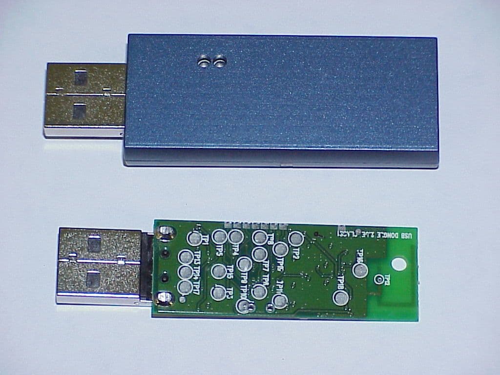
Click to zoom
Application Details
- Equipment Class
- DSS - Part 15 Spread Spectrum Transmitter
- Date of Grant
- Dec 30, 2002
- Application Purpose
- Original Equipment
- Date of Application
- Dec 30, 2002
- Equipment Note
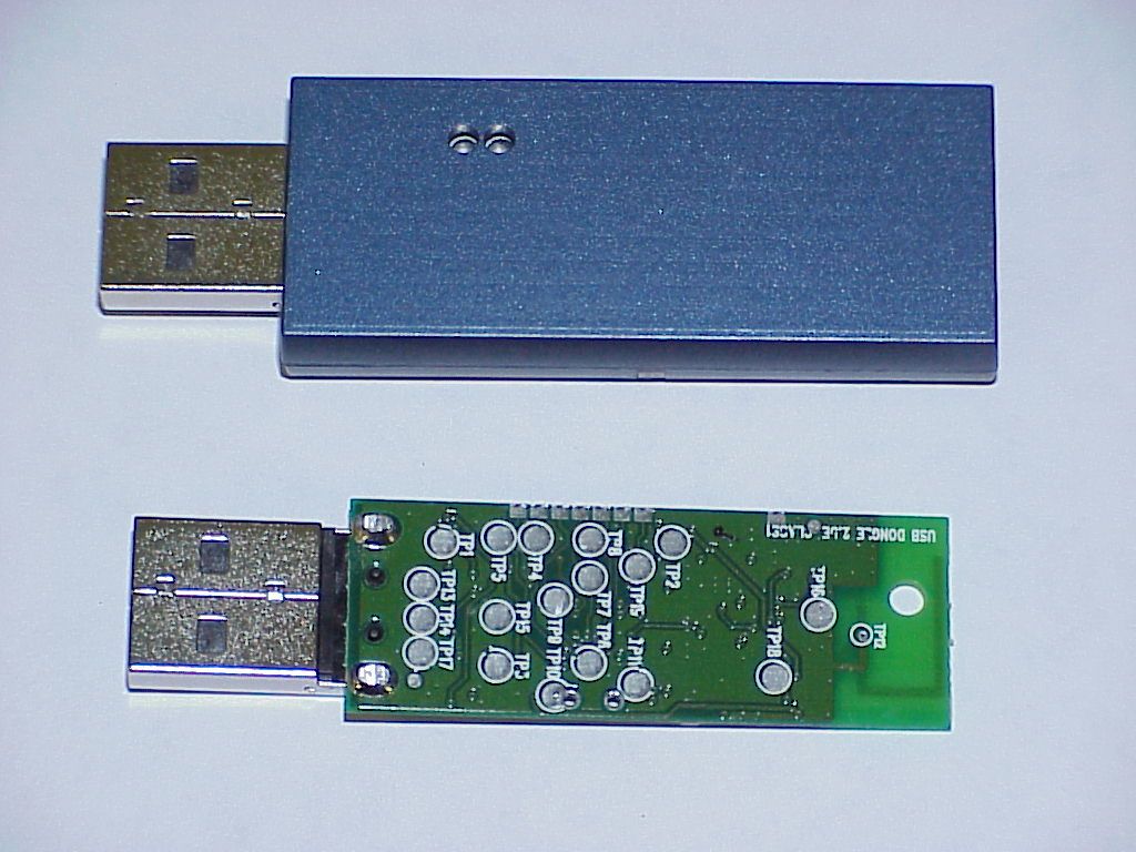
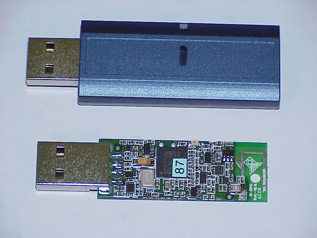
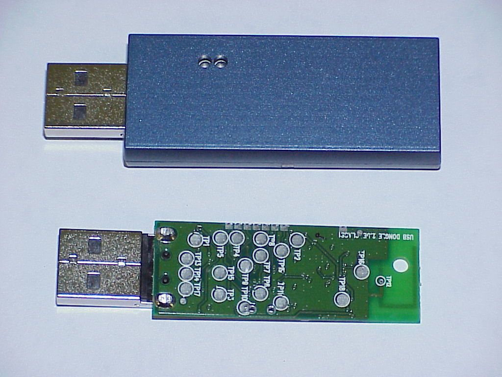
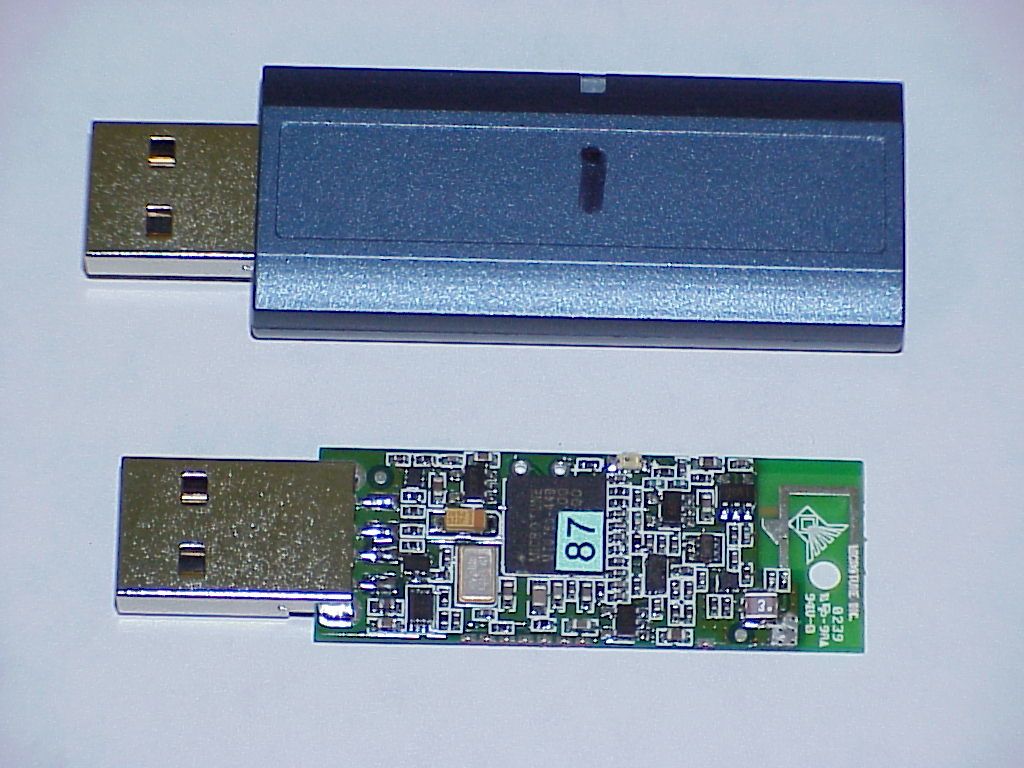
- Bluetooth USB Dongle, Class 1
- Frequency Range
- 2402.00000000 - 2480.00000000
- Company
- Microtune, Inc.
- Country
- United States
Documents & Files
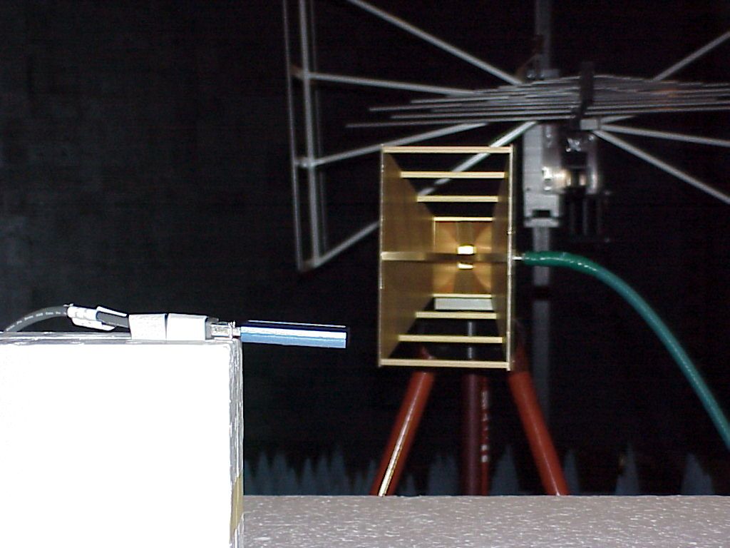
Document Text
Text extracted from the exhibit documents filed with the FCC. Open a document above to read the original.
Users Manual
Microtune, Inc. Bluetooth USB Dongle User Manual MT0760-UD1P • •• • MT0760-UD2P MT0760-UDW1P • •• • MT0760-UDW2P Host Requirements The Microtune OneChip Solution for Windows software supports the following operating systems: •=Windows 98SE •=Windows ME •=Windows 2000 •=Windows XP If using other host-based software, please consult the related documentation. Package Contents The Microtune MT0760-UDW1P USB Dongle Bundle should contain the following items: •=MT0760-UD1P USB Dongle •=MT-OSW CD The Microtune MT0760-UDW2P USB Dongle Bundle should contain the following items: •=MT0760-UD2P USB Dongle •=MT-OSW CD Instructions Installation Plug the USB dongle in prior to installing the Bluetooth host software. •=For MT0760-UDW1P or MT0760-UDW2P, install software from included MT-OSW CD Usage Plug MT0760-UD1P or MT0760-UD2P USB Dongle into an available USB port on the computer When connected, the green LED will light Windows will recognize new hardware Run host-based Bluetooth software to enable use with a Bluetooth device Technical Support If you experience problems, please contact: Microtune, Inc. Wireless Connectivity Business Unit 6440 Lusk Blvd. Suite D-205 San Diego, CA 92121 USA Phone: 858.558.6088 Fax: 858.558.6598 Microtune Bluetooth USB Dongle User Manual MT0760-UD1P • •• • MT0760-UD2P MT0760-UDW1P • •• • MT0760-UDW2P World Headquarters•Microtune, Inc., 2201 Tenth Street, Plano, TX 75074 USA•Tel: 972-673-1600, Fax: 972-673-1602, E-mail: [email protected], Web site: www.microtune.com Wireless Headquarters•Microtune, Inc. Wireless Connectivity Business Unit, 6440 Lusk Blvd. Suite D-205, San Diego, CA 92121 USA•Tel: 858-558- 6088, Fax: 858-558-6598 Europe•Microtune GmbH and Co. KG, Marie Curie Strasse 1, 85055 Ingolstadt / Germany•Tel: +49-841-9378-020, Fax: +49-841-9378-024 Japan•Microtune (Japan) Ltd., Kawasho Building 4F, 3-10 Nihonbashi Kodemmacho, Chuo-ku, Tokyo 103-0001•Tel: +81-3-5652-0250, Fax: +81-3-5652-0251 Taiwan•Microtune (Taiwan) Ltd., 18F-7, No.77, Sec.1, Hsin Tai Wu Rd., Hsi-Chih, Taipei Hsien, Taiwan, R.O.C.•Tel: +886-2-2698-8648, Fax: +886-2- 2698-8647 For a detailed list of current sales representatives, visit our Web site at www.microtune.com. The information in this document is believed to be accurate and reliable. Microtune assumes no responsibility for any consequences arising from the use of this information, nor from any infringement of patents or the rights of third parties which may result from its use. No license i s granted by implication or otherwise under any patent or other rights of Microtune. The information in this publication replaces and supersedes all information previously supplied, and is subject to change without notice. The customer is responsible for assuring that proper design and operating safeguards are observed to minimize inherent and procedural hazards. Microtune assumes no responsibility for applications assistance or customer product design. The devices described in this document are not authorized for use in medical, life-support equipment, or any other application involving a potential risk of severe property or environmental damage, personal injury, or death without prior express written approval of Microtune. Any such us e is understood to be entirely at the user’s risk. Microtune, MicroTuner, MicroModule, and the Microtune logo are trademarks of Microtune, Inc. All other trademarks belong to their respective companies. Microtune’s products are protected by one or more of the following U.S. patents: 5,625,325; 5,648,744; 5,717,730; 5,737,035; 5,739,730; 5,805,988; 5,847,612; 6,100,761; 6,104,242; 6,144,402; 6,163,684; 6,169,569; 6,177,964; 6,218,899 and additional patents pending or filed. Entire contents Copyright © 2001 Microtune, Inc. Products not to be used in life support or safety applications. Regulatory Information This product complies with the regulations of the following organizations: •=FCC •=European Union (EU) and EFTA •=Bluetooth SIG This equipment is Bluetooth 1.1 qualified according to specification. MT0760-UD Hardware Specifications BLUETOOTH WIRELESS CONNECTION SPECIFICATION MT0760-UD2 MT0760-UD1 Radio class Class 2 (1.5 dBm) Class 1 (20 dBm) Range, 0.1% BER (> 500kbps) > 10m (30 ft) > 60m (200 ft) Power consumption (DM5) 50 mA 120 mA Frequency range 2.400 to 2.4835 GHz Data throughput 1 Mbps (723 kBps effective rate) ACL data DM1/DH1, DM3/DH3, DM5/DH5, AUX1 Power management Sniff, park, and hold Encryption 128 bit Antenna Horizontal plane (1.7 dBi) USB CONNECTION SPECIFICATIONS USB type USB version 1.1 slave USB data input 12 Mbps USB power input 5V required from host USB connector type Standard USB male type A DONGLE GENERAL SPECIFICATIONS Dongle temperature range -20° to +50° C Dongle firmware LM, LC, HCI Certification and regulatory USB1.1, BT1.1, FCC, CE MT-OSW Software Specifications BLUETOOTH HOST SOFTWARE Host stacks HCI, L2CAP, RFCOMM, SDP, OBEX Application profiles GAP, SDAP SPP client and server DUN client and server LAN client and server FAX client GEOP, OPP, FTP, SYNC HSP Operating system support Windows 98 Windows 2000 Windows ME Windows XP This device complies with Part 15 of the FCC Rules. Operation is subject to the following two conditions: (1) this device may not cause harmful interference, and (2) this device must accept any interference received, including interference that may cause undesired operation. Statement according FCC part 15.21 Modifications not expressly approved by Microtune, Inc. could void the user's authority to operate the equipment. Statement according FCC part 15.105 NOTE: This equipment has been tested and found to comply with the limits for a Class B digital device, pursuant to Part 15 of the FCC Rules. These limits are designed to provide reasonable protection against harmful interference in a residential installation. This equipment generates, uses and can radiate radio frequency energy and, if not installed and used in accordance with the instructions, may cause harmful in…
Text truncated - open the document above for the full version.
Block Diagram
Block Diagram MT0760-UD1P
Cover Letter(s)
Federal Communication Commission Equipment Authorization Division, Application Processing Branch 7435 Oakland Mills Road Columbia, MD 21048 December 27, 2002 TO WHOM IT MAY CONCERN Pursuant to Paragraphs §0.457 and 0.459 of the Commission’s Rules (47 C.F.R.) and Section §552(b)(4) of the Freedom of Information Act, Microtune, Inc. requests confidentiality for the following product: FCC ID Number Product Title/Model QR8-MT0760UD1P MT0760-UD1P For the product stated above, we request that the following information be held confidential: 1) Exhibit 1. Electrical Schematics of the Circuitry: Schematics SC-00048-1-0 2) Exhibit 2. Tune-up procedure: SPEC-00038 USB Dongle Production Development Rev 03 3) Exhibit 3. Bill of materials: BOM-class 1 No other items submitted as part of the equipment authorization filing process are deemed confidential. The above exhibits contain Microtune, Inc. trade secrets and proprietary information that could be of benefit to our competitors regarding the design of our mobile handset. This material is not customarily available to the general public and we request that it be withheld from public inspection. If you have any questions, please feel free to contact me at the address shown below. Sincerely, Pete Krebill Engineer Cetecom Inc. 411 Dixon Landing Rd Milpitas, CA 95035 (408) 586-6200
ID Label/Location Info
Microtune USB Slave dongle
ID Label/Location Info
Microtune, Inc.MT0760-UD1P Input: DC 5V FCC ID: QR8-MT0760UD1PClass 1Made in the Philippines 37.8 ± 0.2mm USB Dongle Class 1 Label (approved) 17.8 ± 0.2mm Letter Height 1.45 mm Arial Bold Letter Height 1.3 mm Arial Letter Height 1.3 mm Arial Logo 5 x 5 mm Logo 4 x 4 mm(All 3 logos)
Operational Description
Microtune USB Dongle : Cable free MT0760-CF30/100 Operational Description Hopping sequence is generated (pseudorandomly) In total, 10 types of hopping sequences are defined .five for the 79-hop and five for the 23-hop system, respectively. Using the notation of parentheses () for figures related to the 23-hop system, these sequences are: •A page hopping sequence with 32 (16) unique wake-up frequencies dis-tributed equally over the 79 (23) MHz, with a period length of 32 (16); •A page response sequence covering 32 (16) unique response frequencies that all are in an one-to-one correspondence to the current page hopping sequence. The master and slave use different rules to obtain the same sequence; •An inquiry sequence with 32 (16) unique wake-up frequencies distributed equally over the 79 (23) MHz, with a period length of 32 (16); •A inquiry response sequence covering 32 (16) unique response frequen-cies that all are in an one-to-one correspondence to the current inquiry hop-ping sequence. •A channel hopping sequence which has a very long period length, which does not show repetitive patterns over a short time interval, but which dis-tributes the hop frequencies equally over the 79 (23) MHz during a short time interval; For the page hopping sequence, it is important that we can easily shift the phase forward or backward, so we need a 1-1 mapping from a counter to the hop frequencies. For each case, both a hop sequence from master to slave and from slave to master are required. The inquiry and inquiry response sequences always utilizes the GIAC LAP as lower address part and the DCI as upper address part in deriving the hopping sequence, even if it concerns a DIAC inquiry. Example of the hopping sequence channels (hopset table) The selection scheme consists of two parts: • selecting a sequence; • mapping this sequence on the hop frequencies; The general block diagram of the hop selection scheme is shown in 1. The mapping from the input to a particular hop frequency is per-formed in the selection box. Basically, the input is the native clock and the cur-rent address. In CONNECTION state, the native clock (CLKN) is modified by an offset to equal the master clock (CLK). Only the 27 MSBs of the clock are used. In the page and inquiry substates, all 28 bits of the clock are used. How- ever, in page substate the native clock will be modified to the master’s estimate of the paged unit. The address input consists of 28 bits, i.e., the entire LAP and the 4 LSBs of the UAP. In CONNECTION state, the address of the master is used. In page sub-state the address of the paged unit is used. When in inquiry substate, the UAP/LAP corresponding to the GIAC is used. The output constitutes a pseudo- random sequence, either covering 79 hop or 23 hops, depending on the state. For the 79-hop system, the selection scheme chooses a segment of 32 hop frequencies spanning about 64 MHz and visits these hops once in a random order. Next, a different 32-hop segment is chosen, etc. In case of the page, page scan, or page response substates, the same 32-hop segment is used all the time (the segment is selected by the address; different units will have differ-ent paging segments). In connection state, the output constitutes a pseudo-random sequence that slides through the 79 hops or 23 hops, depending on the selected hop system. Figure 1. For the 79-hop system, the selection scheme chooses a segment of 32 hop frequencies spanning about 64 MHz and visits these hops once in a random order. Next, a different 32-hop segment is chosen, etc. In case of the page, page scan, or page response substates, the same 32-hop segment is used all the time (the segment is selected by the address; different units will have differ-ent paging segments). In connection state, the output constitutes a pseudo-random sequence that slides through the 79 hops or 23 hops, depending on the selected hop system. The principle is depicted in Figure 2.0 SELECTION BOX ULP/LAP CLOCK 28 27 Hop Frequencies 23/79 mode 0 64...............781.......................77 Seg 1 Seg 2 Seg 3 The hop selection kernels for the 79 hop system are shown in Figure 3.0 The X input determines the phase in the 32-hop segment, whereas Y1 and Y2 selects between master-to-slave and slave-to-master transmission. The inputs A to D determine the ordering within the segment, the inputs E and F determine the mapping onto the hop frequencies. The kernel addresses a register containing the hop frequencies. This list should be created such that first all even hop fre- quencies are listed and then all odd hop frequencies. In this way, a 32-hop seg-ment spans about 64 MHz, whereas a 16-hop segment spans the entire 23-MHz. Figure 3.0 The selection procedure consists of an addition, an XOR operation, a permuta-tion operation, an addition, and finally a register selection. In the remainder of this chapter, the notation A i is used for bit i of the BD_ADDR. 11.2.1 First addition operation The first addition operation only adds a constant to the phase and applies a modulo 32 or a modulo 16 operation. For the page hopping sequence, the first addition is redundant since it only changes the phase within the segment. How- ever, when different segments are concatenated (as in the channel hopping sequence), the first addition operation will have an impact on the resulting sequence. ADD XOR PERM4 ADD A B CD EF MOD 16 Y2 XOR 0 2 4 . . 22 1 3 5 . . 21 11.2.2 XOR operation Let Z’ denote the output of the first addition. In the XOR operation, the four LSBs of Z’ are modulo-2 added to the address bits A 22-19 . The permutation operation involves the switching from 5 inputs to 5 outputs for the 79 hop system and from 4 inputs to 4 outputs for 23 hop system, in a manner controlled by the control word. Table 1 shows the control of the butterflies by the control signals P. Note that P 0-8 corresponds to D 0-8 , and, corresponds to for in Figure 3.0 Control Control Signal Butterfly signal Butterfly P 0 {Z 0 ,Z 1 } …
Text truncated - open the document above for the full version.
Test Report
CETECOM Inc. CETECOM Inc. 411 Dixon Landing Road, Milpitas, CA-95035, USA Phone: +1 408 586 6200 Fax: +1 408 586 6299 www.cetecom.com Issued test report consists of 62 Pages Page 1 (62) FCC15.247-FHSS-A Test report no.: 361FCC15.247/2002 FCC Part 15.247 for FHSS systems / CANADA RSS-210 (MT0760-UDIP Bluetooth USB Dongle Class 1) FCC LISTED, REG. NO.: 101450 & RECOGNIZED BY INDUSTRY CANADA IC – 3925 CETECOM Inc. Test report no.:EMC361FCC15.247/2002 Issue date:2002-12-20 Page 2 (62) Table of Contents 1 General information 1.1 Notes 1.2 Testing laboratory 1.3 Details of applicant 1.4 Application details 1.5 Test item 1.6 Test standards 2 Technical test 2.1 Summary of test results 2.2 Test report 1 General information 1.1 Notes The test results of this test report relate exclusively to the test item specified in 1.5. The CETECOM Inc. USA does not assume responsibility for any conclusions and generalisations drawn from the test results with regard to other specimens or samples of the type of the equipment represented by the test item. The test report may only be reproduced or published in full. Reproduction or publication of extracts from the report requires the prior written approval of the CETECOM Inc USA. TEST REPORT PREPARED BY: EMC Engineer: Mark Sechrist 1.2 Testing laboratory CETECOM Inc. 411 Dixon Landing Road, Milpitas, CA-95035, USA Phone: +1 408 586 6200 Fax: +1 408 586 6299 E-mail: [email protected] Internet: www.cetecom.com CETECOM Inc. Test report no.:EMC361FCC15.247/2002 Issue date:2002-12-20 Page 3 (62) 1.3 Details of applicant Name : Microtune Inc. Street : 6440 Lusk Blvd., Suite D-205 City / Zip Code : San Diego, CA 92121 Country : U.S.A. Contact : Kevin Lynaugh Telephone : (858) 558-6088 ext. 197 Tele-fax : (858) 558-6598 e-mail : [email protected] 1.4 Application details Date of receipt of application : 10/16/02 Date of receipt test item : 10/16/02 Date of test : 10/22/02, 10/23/02, 12/19/02, 12/20/02 1.5 Test item Manufacturer : Microtune Inc. Street Address : 6440 Lusk Blvd., Suite D-205 City / Zip Code : San Diego, CA 92121 Country : U.S.A. Marketing Name : Bluetooth USB Dongle Class 1 Model No. : MT0760-UD1P Description : Wireless USB connectivity between Window’s based hosts and common peripheral devices. FCC-ID : QR8-MT0760UD1P Additional information Frequency : 2402-2480 MHz Type of modulation : GFSK Number of channels : 79 Antenna : Internal Power supply : 3.7 volt Output power : Class 1 Extreme vol. Limits : 3.1 volt to 3.7 volt Extreme temp. Tolerance : 0 to 55 degrees celsius 1.6 Test standards: FCC Part 15 §15.247 (DA00-705) Note: All radiated measurements were made in all three orthogonal planes. The values reported are the maximum values. CETECOM Inc. Test report no.:EMC361FCC15.247/2002 Issue date:2002-12-20 Page 4 (62) 2 Technical test 2.1 Summary of test results No deviations from the technical specification(s) were ascertained in the course of the tests Performed Final Verdict: (only “passed” if all single measurements are “passed”) Passed Technical responsibility for area of testing: 2002-xx-xx EMC & Radio Lothar Schmidt (Manager) Date Section Name Signature Responsible for test report and project leader: 2002-12-20 EMC & Radio Mark Sechrist (EMC Engineer) Date Section Name Signature CETECOM Inc. Test report no.:EMC361FCC15.247/2002 Issue date:2002-12-20 Page 5 (62) 2.2 Test report TEST REPORT Test report no. : EMC361FCC15.247/2002 (MT0760-UD1P Bluetooth USB Dongle Class 1) CETECOM Inc. Test report no.:EMC361FCC15.247/2002 Issue date:2002-12-20 Page 6 (62) TEST REPORT REFERENCE ANTENNA GAIN § 15.204 7 CARRIER FREQUENCY SEPERATION §15.247(a) 8 NUMBER OF HOPPING CHANNELS §15.247(a) 9 TIME OF OCCUPANCY (DWELL TIME) §15.247(a) 13 SPECTRUM BANDWIDTH OF FHSS SYSTEM §15.247(a) 16 POWER SPECTRAL DENSITY §15.247 (d) 20 MAXIMUM PEAK OUTPUT POWER (conducted) § 15.247 (b) (1) 24 MAXIMUM PEAK OUTPUT POWER (Radiated) § 15.247 (b) (1) 28 BAND EDGE COMPLIANCE §15.247 (c) 32 EMISSION LIMITATIONS (Transmitter conducted) § 15.247 (c) (1) 40 EMISSION LIMITATIONS (Transmitter radiated) § 15.247 (c) (1) 47 RECEIVER SPURIOUS RADIATION § 15.209 56 TEST EQUIPMENT AND ANCILLARIES USED FOR TESTS 60 BLOCK DIAGRAMS 61 CETECOM Inc. Test report no.:EMC361FCC15.247/2002 Issue date:2002-12-20 Page 7 (62) ANTENNA GAIN § 15.204 The antenna gain of the complete system is calculated by the difference of conducted power of the module and the radiated power in EIRP. Low channel Mid channel High channel Conducted Power 11.81 dBm 12.02 dBm 12.24dBm Raidated Power (EIRP) 10.53 dBm 10.26 dBm 9.87 dBm Antenna Gain -1.28 dBi -1.76 dBi -2.37 dBi The calculated antenna gain is between –1.28 dBi and –2.37 dBi. CETECOM Inc. Test report no.:EMC361FCC15.247/2002 Issue date:2002-12-20 Page 8 (62) CARRIER FREQUENCY SEPERATION §15.247(a) Cfs.wmf CETECOM Inc. Test report no.:EMC361FCC15.247/2002 Issue date:2002-12-20 Page 9 (62) NUMBER OF HOPPING CHANNELS §15.247(a) The number of hopping channels is 79 (see next 4 plots) The right red line corresponds to the left red line from the next plot. Plot 1: Total 23 Plot-1.wmf CETECOM Inc. Test report no.:EMC361FCC15.247/2002 Issue date:2002-12-20 Page 10 (62) Plot 2: Total 25 Plot-2.wmf CETECOM Inc. Test report no.:EMC361FCC15.247/2002 Issue date:2002-12-20 Page 11 (62) Plot 3: Total 20 Plot-3.wmf CETECOM Inc. Test report no.:EMC361FCC15.247/2002 Issue date:2002-12-20 Page 12 (62) Plot 4: Total 11 Plot-4.wmf CETECOM Inc. Test report no.:EMC361FCC15.247/2002 Issue date:2002-12-20 Page 13 (62) TIME OF OCCUPANCY (DWELL TIME) §15.247(a) DH1 – Packet The system makes worst case 1600 hops per second or 1 time slot has a length of 625μs with 79 channels. A DH1 Packet need 1 time slot for transmitting and 1 time slot for receiving. Then the system makes worst case 800 hops per second with 79 channels. So you have each channel 10.13 times per second and so for 30 seconds you have 303.9 times of appearence . Each Tx-time per appearence is xxxx μs. So we…
Text truncated - open the document above for the full version.
Test Report
CETECOM Inc. Milpitas, USA EUT: BT USB Dongle plugged into laptop Manufacturer: Microtune Operating mode: Tx at 2441MHz Test Engineer: Harpreet Sidhu LISN: L+N Comment: Spec: FCC 15.247/15.209 SWEEP TABLE: "55022 cond" Short Description: EN 55022 for 150KHz-30MHz Start Stop Detector Meas. IF Transducer Frequency Frequency Time Bandw. 150.0 kHz 30.0 MHz MaxPeak Coupled 10 kHz None SCAN TABLE: "55022 V AV" Short Description: Cable Calibration Start Stop Step Detector Meas. IF Transducer Frequency Frequency Width Time Bandw. 150.0 kHz 30.0 MHz 10.0 % MaxPeak 1.0 s 9 kHz None Average -30-20 0 20406080 Level [dBμV] 150k 300k 500k 1M 2M 3M 4M 6M 10M 30M Frequency [Hz] MES vol_0001_pre PK MES vol_0001_pre AV LIM EN 55022 V QP Voltage QP LimitLIM EN 55022 V AV Voltage AV Limit
Contact Information
Applicant
Hidekazu Nakama(VP Engineering)
Technical Contact
CETECOM Inc.Lothar Schmidt
[email protected]408-586-6214
411 Dixon Landing · Milpitas, California · United States
Non-Technical Contact
CETECOM Inc.Lothar Schmidt
[email protected]408-586-6214
Test Firm
Cetecom Inc.Lothar Schmidt
Technical Specifications
| # | Rule Parts | Frequency Range | Power Output |
|---|---|---|---|
| 1 | 15C | 2.40 GHz - 2.48 GHz | 11.30 mW |
Other Applications from Microtune, Inc.
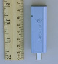
QR8-MT0760UM1PCF
Feb 24, 2003Cable Free USB Master Class 1
Equipment Class
DSS - Part 15 Spread Spectrum Transmitter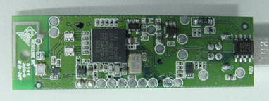
QR8-MT0760UM2PCF
Feb 24, 2003Cable Free USB Master Class 2
Equipment Class
DSS - Part 15 Spread Spectrum Transmitter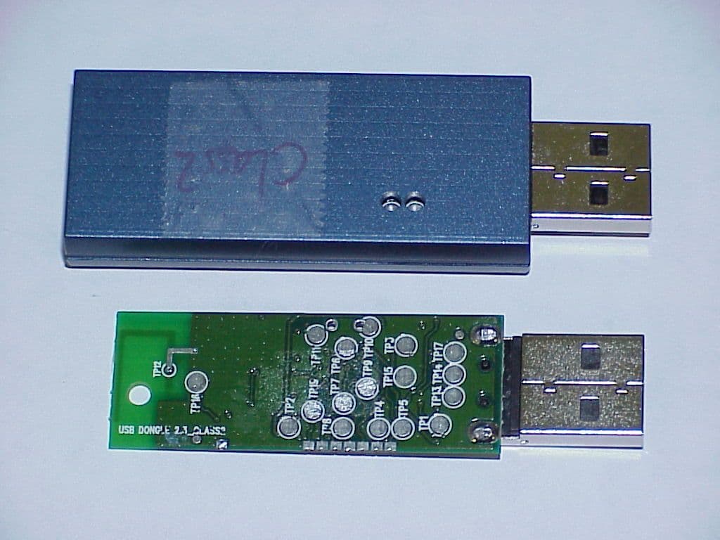
QR8-MT0760UD2P
Dec 30, 2002Bluetooth USB Dongle, Class 2
Equipment Class
DSS - Part 15 Spread Spectrum Transmitter