QR8-MT0760UM2PCFCable Free USB Master Class 2
Microtune, Inc.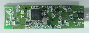
Click to zoom
Application Details
- Equipment Class
- DSS - Part 15 Spread Spectrum Transmitter
- Date of Grant
- Feb 24, 2003
- Application Purpose
- Original Equipment
- Date of Application
- Feb 24, 2003
- Equipment Note
- Cable Free USB Master Class 2
- Frequency Range
- 2402.00000000 - 2480.00000000
- Company
- Microtune, Inc.
- Country
- United States
Documents & Files
Document Text
Text extracted from the exhibit documents filed with the FCC. Open a document above to read the original.
Users Manual
Microtune, Inc. “CableFree USB” Kit User Manual MT0760-CF30 • MT0760-CF100 Patent Pending USB Dongle Specifications Bluetooth Wireless Connection Specification Standard Bluetooth version 1.1 Frequency Range 2.400 to 2.4835 GHz Radio Type Class 2 (MT0760-CF30) Class 1 (MT0760-CF100) Range 30 ft (MT0760-CF30) 100 ft (MT0760-CF100) Data Throughput 100 Kbps USB Connection Specifications USB Standard USB version 1.1 USB Connector Type USB Male Type “A” (Slave) USB Male Type “B” (Master) USB Power Input Requirement 5V (From Host or PS) USB Master Power Output 5V (to Peripheral with use of PS) Dongle General Specifications Master Power Connector 1.3mm Jack Connector (5V +/-5% External Supply Required) Dongle Operation Indication Green LED Dongle Temperature Range -20 to +50C Certification & Regulatory USB1.1, BT1.1, FCC, CE Interoperability & USB Device Conformance Printers – Most HP, Cannon Scanners – Most HP, Cannon Cameras – PTP Conformance Host Requirements Wireless USB connectivity can be achieved between Windows-based hosts and common peripheral devices. Package Contents The Microtune MT0760-CF30 USB “CableFree USB” Kit should contain the following items: • MT0760-UD2P USB Slave Dongle with ”A” type connector • MT0760-UM2P USB Master Dongle with ”B” type connector and 5V power jack • PS5-USB-NA 5V Regulated Wall Adapter North American Power Supply • C-USB-A/B Receptacle Adapter The Microtune MT0760-CF100 USB “CableFree USB” Kit should contain the following items: • MT0760-UD1P USB Slave Dongle with ”A” type connector • MT0760-UM1P USB Master Dongle with ”B” type connector and 5V power jack • PS5-USB-NA 5V Regulated Wall Adapter North American Power Supply • C-USB-A/B Receptacle Adapter Instructions Installation • Connect the MT0760-UD1P/MT0760- UD2P slave dongle to the PC at an available USB port • Connect the MT0760-UM1P/MT0760- UM2P master dongle to the peripheral’s USB port • Attach power supply to port on MT0760- UM1P/MT0760-UM2P master dongle and plug into wall socket Usage • Use peripheral in accordance with usage of a standard USB cable. • The MT0760-CF30 will allow wireless connectivity up to a range of 30 feet, the MT0760-CF100 will extend to 100 feet. DRAFT Microtune “CableFree USB”Kit User Manual MT0760-CF30• MT0760-CF100 Patent Pending World Headquarters • Microtune, Inc., 2201 Tenth Street, Plano, TX 75074 USA • Tel: 972-673-1600, Fax: 972-673-1602, E-mail: [email protected], Web site: www.microtune.com Wireless Headquarters • Microtune, Inc. Wireless Connectivity Business Unit, 6440 Lusk Blvd. Suite D-205, San Diego, CA 92121 USA • Tel: 858-558-6088, Fax: 858-558-6598 Europe • Microtune GmbH and Co. KG, Marie Curie Strasse 1, 85055 Ingolstadt / Germany • Tel: +49-841-9378-020, Fax: +49-841-9378-024 Japan • Microtune (Japan) Ltd., Kawasho Building 4F, 3-10 Nihonbashi Kodemmacho, Chuo-ku, Tokyo 103-0001• Tel: +81-3-5652-0250, Fax: +81-3-5652-0251 Taiwan • Microtune (Taiwan) Ltd., 18F-7, No.77, Sec.1, Hsin Tai Wu Rd., Hsi-Chih, Taipei Hsien, Taiwan, R.O.C. • Tel: +886-2-2698-8648, Fax: +886-2-2698-8647 For a detailed list of current sales representatives, visit our Web site at www.microtune.com. The information in this document is believed to be accurate and reliable. Microtune assumes no responsibility for any consequences arising from the use of this information, nor from any infringement of patents or the rights of third parties which may result from its use. No license is granted by implication or otherwise under any patent or other rights of Microtune. The information in this publication replaces and supersedes all information previously supplied, and is subject to change without notice. The customer is responsible for assuring that proper design and operating safeguards are observed to minimize inherent and procedural hazards. Microtune assumes no responsibility for applications assistance or customer product design. The devices described in this document are not authorized for use in medical, life-support equipment, or any other application involving a potential risk of severe property or environmental damage, personal injury, or death without prior express written approval of Microtune. Any such use is understood to be entirely at the user’s risk. Microtune, MicroTuner, MicroModule, and the Microtune logo are trademarks of Microtune, Inc. All other trademarks belong to their respective companies. Microtune’s products are protected by one or more of the following U.S. patents: 5,625,325; 5,648,744; 5,717,730; 5,737,035; 5,739,730; 5,805,988; 5,847,612; 6,100,761; 6,104,242; 6,144,402; 6,163,684; 6,169,569; 6,177,964; 6,218,899 and additional patents pending or filed. Entire contents Copyright © 2001 Microtune, Inc. Products not to be used in life support or safety applications. This device complies with Part 15 of the FCC Rules. Operation is subject to the following two conditions: (1) this device may not cause harmful interference, and (2) this device must accept any interference received, including interference that may cause undesired operation. Statement according FCC part 15.21 Modifications not expressly approved by Microtune, Inc. could void the user's authority to operate the equipment. Statement according FCC part 15.105 NOTE: This equipment has been tested and found to comply with the limits for a Class B digital device, pursuant to Part 15 of the FCC Rules. These limits are designed to provide reasonable protection against harmful interference in a residential installation. This equipment generates, uses and can radiate radio frequency energy and, if not installed and used in accordance with the instructions, may cause harmful interference to radio communications. However, there is no guarantee that interference will not occur in a particular installation. If this equipment does cause harmful interference to radio or television reception, which can be determined by turning the equipment off and on, the user is encouraged to try to correct the interference by…
Text truncated - open the document above for the full version.
Block Diagram
Microtune Master U S B Dongle C2 Block Diagram BluetoothBasebanduP8051 USB Host Controller USB B Ty p e Conn ecto r D+D-GND5V Regul ators LED 6.0MHz CLOCK Printed Antenn a 24.0MHz Crystal GMSK MODEM SW BPF 2. 4~ 2. 5GHz 0~4dB m AGC +5VDC 3V 3.3V IF=2 M H z LPF MT0760 Ferrite Bead PLLVCO Balun PA LNA 2400~248 0M Hz Balun
ID Label/Location Info
Microtune, Inc. MT0760-UM2P-CF Input: DC 5V FCC ID: QR8-MT0760UM2PCF CableFree USB™ Master Class 2 Patent Pending Made in the Philippines
Internal Photos
BOTTOM ZOOM TOP ZOOM
Test Report
TÜV AMERICA, INC. 10040 Mesa Rim Road San Diego, CA 92121-2912 Phone 858 546 3999 FAX 858 546 0364 Report No. SC300105-03A Page 1 of 20 Rev.No 1.0 MEASUREMENT AND TECHNICAL REPORT MICROTUNE INCORPORATED 6440 Lusk Boulevard, Suite D-251 San Diego, CA 92121 DATE: 30 January 2003 This Report Concerns: Original Grant: X Class II Change: Equipment Type: CableFree USB Master Class II, Model MT0760-UM2P Deferred grant requested per 47 CFR 0.457(d)(1)(ii)? Yes: Defer until: No: X Company Name agrees to notify the Commission by: N/A of the intended date of announcement of the product so that the grant can be issued on that date. Transition Rules Request per 15.37? Yes: No: X* (*) FCC Part 15, Paragraph(s) 15.247(a)(1), 15.247(a)(1)(ii), 15.247(b)(1), 15.247(c) Report Prepared by: TÜV AMERICA, INC 10040 Mesa Rim Road San Diego, CA 92121-2912 Phone: 858 546 3999 Fax: 858 546 0364 TÜV AMERICA, INC. 10040 Mesa Rim Road San Diego, CA 92121-2912 Phone 858 546 3999 FAX 858 546 0364 Report No. SC300105-03A Page 2 of 20 Rev.No 1.0 TABLE OF CONTENTS Pages 1.0 GENERAL INFORMATION 3 - 6 1.1 Product Description 3 - 5 1.2 Related Submittal Grant 6 1.3 Tested System Details 6 1.4 Test Methodology 6 1.5 Test Facility 6 1.6 Part 2 Requirements 6 2.0 SYSTEM TEST CONFIGURATION 7 2.1 Justification 7 2.2 EUT Exercise Software 7 2.3 Special Accessories 7 2.4 Equipment Modifications 7 2.5 Configuration of Test System 7 3.0 CHANNEL SEPARATION EQUIPMENT/DATA NUMBER OF HOPPING FREQUENCIES EQUIPMENT/DATA BANDWIDTH EQUIPMENT/DATA TIME OF OCCUPANCY EQUIPMENT/DATA POWER OUTPUT EQUIPMENT/DATA RADIATED SPURIOUS EQUIPMENT/DATA 8 - 19 4.0 ATTESTATION STATEMENT 20 TÜV AMERICA, INC. 10040 Mesa Rim Road San Diego, CA 92121-2912 Phone 858 546 3999 FAX 858 546 0364 Report No. SC300105-03A Page 3 of 20 Rev.No 1.0 1.0 GENERAL INFORMATION 1.1 Product Description General Equipment Description -- NOTE: This information will be input into your test report as shown below. EUT Description USB Host Bluetooth Class2 Dongle EUT Name CableFree USB Master Class2 Model No.: MT0760-UM2P Serial No.: -CF Product Options: with(-UM2P) and without (UM2) plastic housing Configurations to be tested: normal operation Power Requirements Regulations require testing to be performed at typical power ratings in the countries of intended use. (i.e., European power is typically 230 VAC 50 Hz or 400 VAC 50 Hz, single and three phase, respectively) Voltage: 5DCV (If battery powered, make sure battery life is sufficient to complete testing.) # of Phases: -- Current (Amps/phase(max)): -- Current (Amps/phase(nominal)): -- Other -- Other Special Requirements Test Firmware will be provided Typical Installation and/or Operating Environment (ie. Hospital, Small Business, Industrial/Factory, etc.) -- EUT Power Cable Permanent OR n Removable Length (in meters): 1.0 Shielded OR Unshielded Not Applicable TÜV AMERICA, INC. 10040 Mesa Rim Road San Diego, CA 92121-2912 Phone 858 546 3999 FAX 858 546 0364 Report No. SC300105-03A Page 4 of 20 Rev.No 1.0 EUT Interface Ports and Cables Interface Shielding Type Type Termination Connector Type Port Termination EXAMPLE: RS232 o ̋ 2 ̋ o Foil over braid Coaxial Metallized 9-pin D-Sub Characteristic Impedance 6 ̋ o -- EUT Software. Revision Level: Ver 1.44 Description: -- Oscillator Frequencies Frequency Derived Frequency Component # / Location Description of Use 24MHz 24MHz Crystal Y1 System Clk and PLL reference 6MHz 6MHz Crystal Y2 Clk for USB Host controller 2402~2480MHz -- U1 TX/RX Carrier/LO Power Supply Manufacturer Model # Serial # Type -- Switched-mode: (Frequency) Linear Other: Power Line Filters Manufacturer Model # Location in EUT -- TÜV AMERICA, INC. 10040 Mesa Rim Road San Diego, CA 92121-2912 Phone 858 546 3999 FAX 858 546 0364 Report No. SC300105-03A Page 5 of 20 Rev.No 1.0 Critical EMI Components (Capacitors, ferrites, etc.) Description Manufacturer Part # or Value Qty Component # / Location -- EMC Critical Detail -- Describe other EMC Design details used to reduce high frequency noise. -- TÜV AMERICA, INC. 10040 Mesa Rim Road San Diego, CA 92121-2912 Phone 858 546 3999 FAX 858 546 0364 Report No. SC300105-03A Page 6 of 20 Rev.No 1.0 1.2 Related Submittal Grant None 1.3 Tested System Details The FCC ID’s for all equipment, plus descriptions of all cables used in the tested system are: None 1.4 Test Methodology Purpose of Test: To demonstrate compliance with the following tests. TEST FCC CFR 47# PASS/FAIL Channel Separation Number of Hopping Frequencies Bandwidth Time of Occupancy 15.247(a)(1) 15.247(a)(1)(ii) 15.247(a)(1)(ii) 15.247(a)(1)(ii) Pass Pass Pass Pass Power Output Radiated Spurious Band Edge Measurment 15.247(b)(1) 15.247(c) 15.247 Pass Pass Pass Both Conducted and Radiated testing were performed according to the procedures in FCC/ANSI C63.4 and CSA 108.8-M1983. Radiated testing was performed at an antenna-to-EUT distance of 3 meters (1 - 25 GHz). 1.5 Test Facility The open area test site and conducted measurement data were tested by: TÜV AMERICA, INC 10040 Mesa Rim Road San Diego, CA 92121-2912 Phone: 858 546 3999 Fax: 858 546 0364 The Test Site Data and performance comply with ANSI C63.4 and are registered with the FCC, 7435 Oakland Mills Road, Columbia Maryland 21046. All Measurement Data is acquired according to the content of FCC Measurement Procedure and ANSI C63.4, unless supplemented with additional requirements as noted in the test report. TÜV AMERICA, INC. 10040 Mesa Rim Road San Diego, CA 92121-2912 Phone 858 546 3999 FAX 858 546 0364 Report No. SC300105-03A Page 7 of 20 Rev.No 1.0 2.0 SYSTEM TEST CONFIGURATION 2.1 Justification The EUT was initially tested for FCC emissions in the normal operating mode as it will be used while in service. 2.2 EUT Exercise Software None 2.3 Special Accessories None 2.4 Equipment Modifications None 2.5 Configuration of Test System None TÜV AMERICA, INC. 10040 Mesa Rim Road San Diego, CA 92121-2912 Phone 858 546 3999 FAX 858 546 0364 Report No. SC300105-03A Page 8 of 20…
Text truncated - open the document above for the full version.
Contact Information
Applicant
Hidekazu Nakama(VP Engineering)
Test Firm
TUV AmericaJames Owen
Technical Specifications
| # | Rule Parts | Frequency Range | Power Output |
|---|---|---|---|
| 1 | 15C | 2.40 GHz - 2.48 GHz | 600.00 µW |
Other Applications from Microtune, Inc.
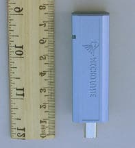
QR8-MT0760UM1PCF
Feb 24, 2003Cable Free USB Master Class 1
Equipment Class
DSS - Part 15 Spread Spectrum Transmitter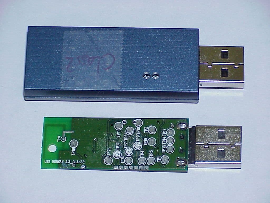
QR8-MT0760UD2P
Dec 30, 2002Bluetooth USB Dongle, Class 2
Equipment Class
DSS - Part 15 Spread Spectrum Transmitter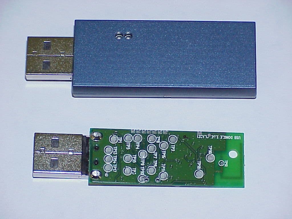
QR8-MT0760UD1P
Dec 30, 2002Bluetooth USB Dongle, Class 1
Equipment Class
DSS - Part 15 Spread Spectrum Transmitter