QRF-TR-3115802.11b Wireless Network Device
Tranzeo Wireless Technologies, Inc
Click to zoom
Application Details
- Equipment Class
- DTS - Digital Transmission System
- Date of Grant
- Apr 14, 2003
- Application Purpose
- Original Equipment
- Date of Application
- Apr 14, 2003
- Equipment Note
- 802.11b Wireless Network Device
- Frequency Range
- 2412.00000000 - 2462.00000000
- Country
- Canada
Documents & Files
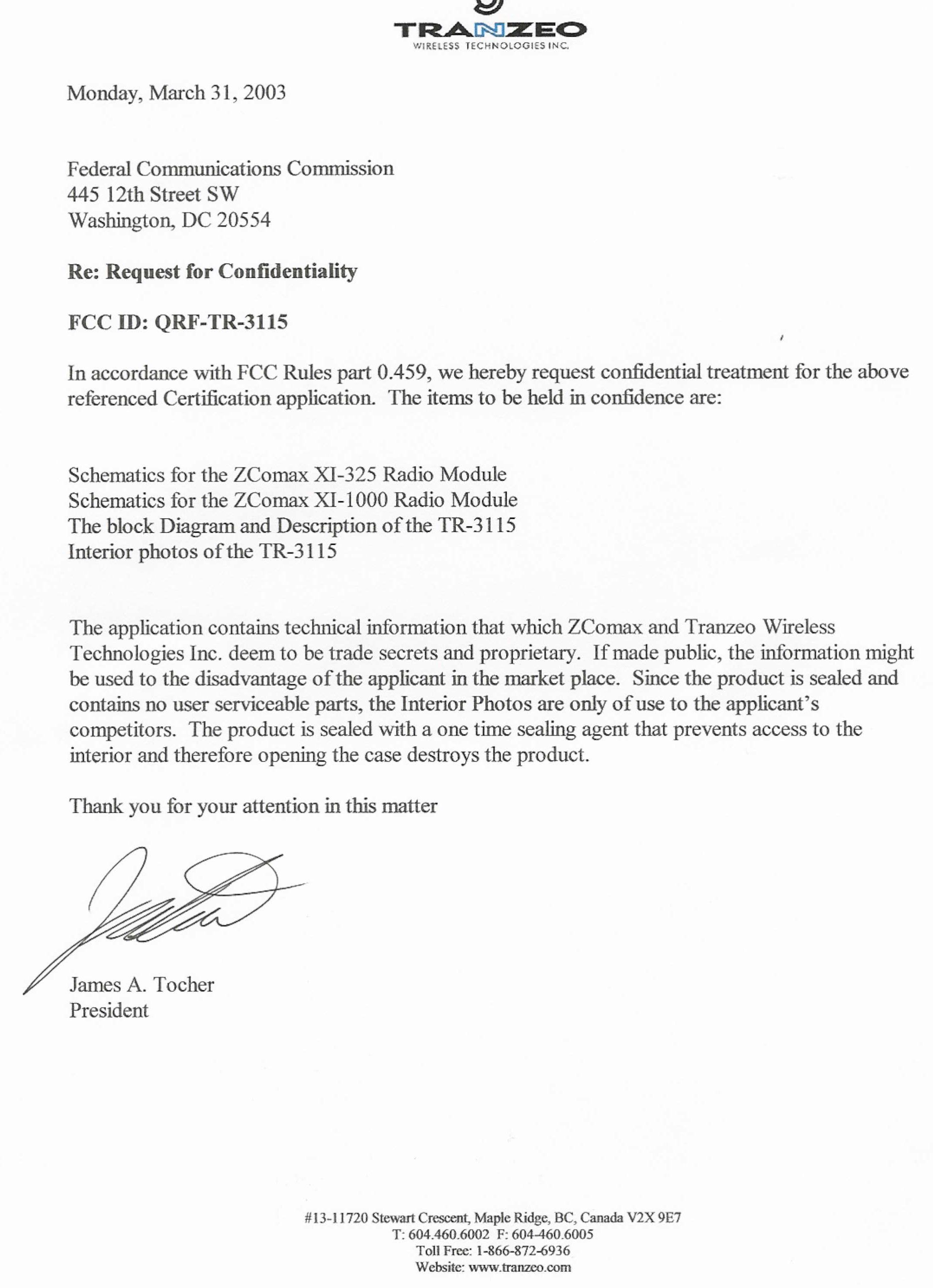
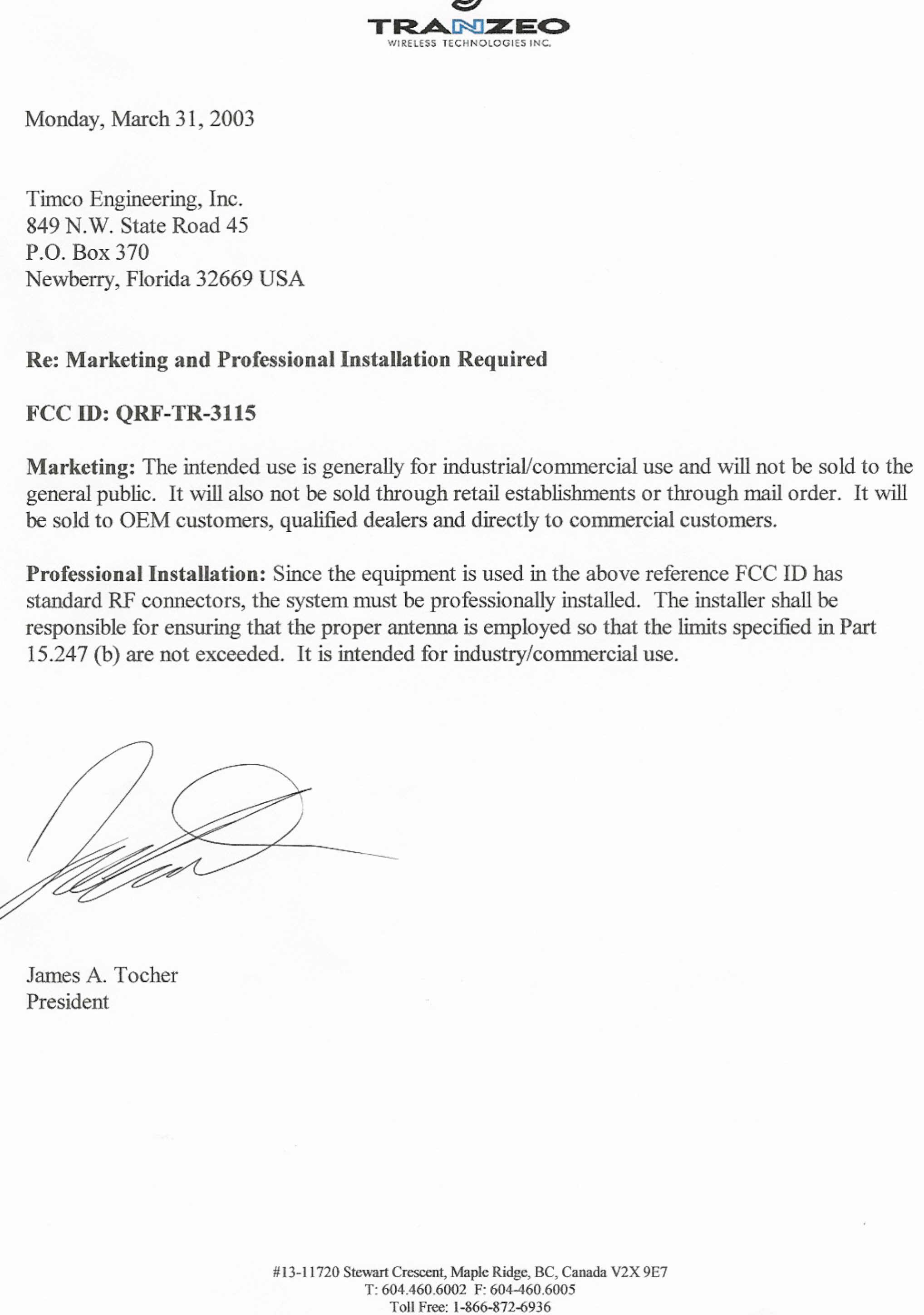
Document Text
Text extracted from the exhibit documents filed with the FCC. Open a document above to read the original.
Users Manual
Quick Start ISP Access Point ISP’s use Access Points to provide you with Internet service. This allows them to send the “Internet” to you wirelessly. The AP talks to Station Adapters and visas versa. ISP’s TR–2015/TR–2018/TR–1000/TR–2000 Unit 1. Plug your Cable, DSL, or other type of Internet service into the uplink port of your hub. (Fig 1) 5 4 Figure 1 Figure 3 From the Hub plug one line into the Ethernet adapter on your computer. Plug a crosspatch cable into the Port marked PC on the DC injector. Plug the TR– 2015/TR–2018/TR–1000/TR–2000 into the port marked CPE on the DC injector. Plug DC power supply into the DC Injector. 5. Set the ESSID by typing in an ID. (Fig 3) Note: You must have an ESSID entered into the box. 6. Hit Apply. Hit OK for reset. 7. Click the IP Address tab and set the TCP/IP Mode to Bridge-Only. (Fig 4) a. Click the DHCP Status Radio Button to receive an address via a DHCP server or select manual to manually assign an IP address. 2. Install the Access Point Utility from the CD. Execute the utility and double click on the icon of the TR– 2015/TR–2018/TR–1000/TR–2000. Enter the Password. The default password is “default”. 3. Click the Configuration tab and then the General tab. Name the Access Point so you can easily identify the unit. (Fig. 2) a. Figure 4 8. Hit Apply. Hit OK to reset. 9. To check signal strength start a telnet session by going to the Start Menu and select Run. Type in “telnet” and the IP of the unit. Enter password. Type “stat” and hit enter. Signal Strength is displayed across the top. Figure 2 4. Click the IEEE802.11 tab and use the drop down menu to set the Radio Mode to Wireless LAN Access Point (AP). (Fig 3) To manage the TR–2015/TR–2018/TR–1000/TR–2000 from inside your network use the gateway’s address to telnet or when using your browser. To remotely manage the TR– 2015/TR–2018/TR–1000/TR–2000 (from an outside location) use the IP address of the TR–2015/TR–2018/TR–1000/TR– 2000. (Fig 5) Figure 5 2 Station Adapter with IP Routing 4 5 IP Routing allows for multiple computers to share a connection. This means that you can have multiple computers using 1 CPE to gain access to your network. You set the CPE to assign IP addresses within a specified range (e.g. 192.168.1.10 to 192.168.1.200). By setting the CPE to Station Adapter Mode the unit is able to send and receive data to and from an Access Point. (Fig 6) Quick Start Figure 6 Setup Figure 8 1. Plug the Cat 5 coming out of the TR-2015/2018/2000 into the port marked CPE on the DC injector. Plug another cable into the PC port on the DC injector and into an Ethernet adaptor for a single PC or into an uplink port on a hub for multiple computers. Note if no uplink port is available, you must use a crosspatch cable. 5. Enter the ESSID of the AP that you wish to connect to. It MUST be the same as the AP that you wish to connect to. 6. Hit Apply. Click OK to reset. 7. For privacy on the network and/ or sharing the connection for multiple computers you need to do the following: (Fig 9) 2. Install the Access Point Utility. Execute the utility and double click on the icon of the CPE. Enter the Password. The default password is “default”. a. Click the IP Address tab and change the TCP/IP Mode from Bridge-Only to IP Router. 3. Click the Configuration tab and then the General tab. Name the Access Point so you can easily identify the unit. (Fig 7) b. Select WAN on the WLA (Wide Area Network on Wireless LAN) radio button. Figure 7 4. Click the IEEE802.11 tab and use the drop down menu to set the Radio Mode to Station Adapter – Infrastructure (SAI). (Fig 8) a. b. Figure 9 From here there are two possible routes to choose, DHCP or Manual. 3 IF You Choose Manual then: i. Ensure that the subnets are the same in the IP Address and the Range of IP’s that you wish to have given out (the third number in the IP Address). 1. Click on the Setup Button above the WAN on WLA and WAN on ETH (Wide Area Network on Ethernet) radio buttons. a. Set the Obtain radio buttons to “Manual” and set the IP Address (for management purposes e.g. telnet, pining etc...), netmask, and gateway. If you wish the have a DHCP server on the LAN side to assign DNS values etc... follow the steps below: (Follow the steps outlined after this section if you wish to manually configure those units) b. Check the NAT (IP Sharing) through this port box. (Fig 10 a) a. Check the box c. Turn off PPPoE by clicking the no. b. Set the range of IP’s that you want to have given out to the multiple computers that can be connected to this CPE. a. 4 b. c. a. b. d. c. Figure 12 a Figure 10 a c. Set the Gateway to XXX.XXX.XXX.254 or XXX.XXX.XXX.1 2. Close the window by hitting the close button. i. Ensure that the subnets are the same. d. Enter the DNS settings into the boxes. If you have DHCP Client enabled on your PC the unit will send all relevant information to your PC automatically. 4. Hit Apply. . For multiple computers do the following: a. Follow steps 1-4 and then follow below. b. Plug the Cable coming out of the CPE into the port marked CPE on your DC Injector. c. Plug a cable into the port marked PC on the DC Injector into the uplink port on the hub or if uplink port is not available use a crosspatch cable. Figure 11 3. d. Plug another Ethernet cable into an available port on the hub and put the other end into the 3. Click the LAN on Ethernet setup button. a. Enter the IP Address into the box marked IP Address. For Windows 98 Users: Ethernet card in your PC. (Fig 12 a) 1. Click Start button, then Settings, then Control Panel. 2. Click the network icon in the list as in Figure 15. Figure 13 a e. Check the connection by opening a web page (that isn’t cached) in your browser. f. Repeat step d. for more computers. To check signal strength start a telnet session by going to the Start Menu and select Run. Type in “telnet” and the IP of the unit. Enter password. Type “stat” and hit enter. Signal Strength is displayed across the top. To manage the CPE from inside yo…
Text truncated - open the document above for the full version.
Users Manual
TR-2000/TR-1000/TR-2015/TR-2018 2 FCC Information This equipment has been tested and found to comply with the limits for a Class A digital devices pursuant to part 15 of the FCC Rules. These limits are designed to provide reasonable protection against harmful interference when the equipment is operated in a commercial environment. This equipment generates, uses, and can radiate radio frequency energy and, if not installed and used in accordance with the instruction manual, may cause harmful interference to radio communication. Operation of this equipment in residential area is likely to cause harmful interference in which case the user will be required to correct the interference at this own expense. The user should not modify or change this equipment without written approval from company name. Modification could void authority to use this equipment. For the safety reason, people should not work in a situation which RF Exposure limits be exceeded. To prevent the situation happening, people who work with the antenna should be aware of the following rules: 1. Install the antenna in a location where a distance of 20 cm from the antenna may be maintained. 2. While installing the antenna in the location, please do not turn on the power of wireless card. 3. While the device is working, please do not contact the antenna. 4. RF exposure: The antenna used for this transmitter must not be co-located or operating in conjunction with any other antenna or transmitter” Copyright Copyright © 2001 all rights reserved. No part of this publication may be reproduced, adapted, stored in a retrieval system, translated into any language, or transmitted in any form or by any means without the written permission of the supplier. About This Manual The purpose of this manual is for the setup of the 11Mbps Wireless LAN Access Point. This manual, revised as version 3.0.0 in 2001, includes procedures assisting you in avoiding unforeseen problems. 3 Table of Contents Chapter 1 Introduction 4 1-1 Features and Benefits 4 1-2 Applications2 4 1-3 System Configurations 5 Chapter 2 Hardware Installation 6 2-1 Product Kit 6 2-2 System Requirements 6 2-3 Mechanical Description 6 2-4 Hardware Installation 6 Chapter 3 Configuring the Access Point 8 3-1 Using the Access Point Manager 8 3-2 Using the Web Management 12 3-3 Using the Console Mode 13 Chapter 4 Troubleshooting 19 Appendix A Network Configuration 19 A-1 Network Topology 20 Appendix B Specifications 20 Appendix C Glossary 21 4 Chapter 1 Introduction The 11Mbps Wireless LAN Access Point is a high-speed wireless unit that performs as a transparent Media Access Control (MAC) bridge between wired Local Area Networks, and one or more wireless networks. It brings Ethernet-like performance to the wireless realm. Placed anywhere along an Ethernet LAN, the 11Mbps Wireless LAN Access Point allows wireless stations in their coverage area to transparently access the corporate network. Fully compliant with the IEEE 802.11(b) standard, the 11Mbps Wireless LAN Access Point also provides powerful features such as the Windows-based configuration utility, WEP security, SNMP and more. The 11Mbps Wireless LAN Access Point enables you to build a variety of network configurations. 1-1 Features and Benefits - Features 11Mbps data rate by incorporating Direct Sequence Spread Spectrum technology - Fully IEEE 802.11b compatible. Allow inter-operation among multiple vendors. - Technique operating in the unlicensed 2.4Ghz ISM band - Seamless roaming within the 802.11 & 802.11b wireless LAN infrastructure - Provides user authentication to enforce tight security - Highly secure system using data encryption levels of 64-bit and 128-bit WEP and MAC Access Control Table - Dynamic Host Configuration Protocol client and server (DHCP) on both Wireless and Ethernet Side - Creates a Point-to-Point and Point-to-Multipoint connection - Highly efficient antenna provides a range of operation up to 800 feet in free space. - Easy to install and friendly to user, just plug and play! - Provides Window-based configuration utilities - Provides Window-based Diagnostic, Statistics Tools and Traffic Monitor - Tight design with light weight, compact size, and low power consumption 1-2 Applications The 11Mbps Wireless LAN products offer a fast, reliable, cost-effective solution for wireless client access to the network in applications like these: 1. Remote access to corporate network information E-mail, file transfer and terminal emulation. 2. Difficult-to-wire environments Historical or old buildings, asbestos installations, and open area where wiring is difficult to deploy. 3. Frequently changing environments Retailers, manufacturers and those who frequently rearrange the workplace and change location. 4. Temporary LANs for special projects or peak time 5 C1- Trade shows, exhibitions and construction sites where a temporary network will be practical. C2- Retailers, airline and shipping companies need additional workstations during peak period. C3- Auditors requiring workgroups at customer sites. 5. Access to database for mobile workers Doctors, nurses, retailers, accessing their database while being mobile in the hospital, retail store or office campus. 6. SOHO (Small Office and Home Office) users SOHO users need easy and quick installation of a small computer network. 7.High security connection The secure wireless network can be installed quickly and provide flexibility. (Please refer to page 19 for more information on encryption configuration.) 1-3 System Configurations The 11Mbp Wireless Access Point can be configured in a variety of network system configurations. Wireless Infrastructure In a wireless infrastructure, the 11Mbps Access Point acts as a bridge. The Access Point connects the wireless clients together. The Access Point acts as a center point for all wireless communications. This would increase efficiency of the communications since the wireless adapters do not need to be within direct range of each othe…
Text truncated - open the document above for the full version.
Cover Letter(s)
Correspondence Summary Questions and Answers April 14, 2003 SUBJECT: TRANZEO WIRELESS TECHNOLOGIES, INC. - FCC ID: QRFTR-3015 TCB Q-1: Part 15.203: Please, could you explain compliance with this section. Applicant A-1: “The Unit is used in exterior conditions, and as previously stated in a one time sealed Case, and removing the case distroys the plate.” TCB Q-2: Test Setup photos: The device under test appears to differ from the device shown in the external photos. Please, explain. Applicant A-2: “As explained in our confidentiality letter, disassembling the unit destroys the plastic casing. In order to take the interior shots, we took the unit apart and then rebuilt it using a slightly different plastic external casing. The back is shown as the device is normally mounted since this was taken at a marketing shoot.” TIMCO ENGINEERING INC. 849 NW State Road 45 Newberry, Florida 32669 http://www.timcoengr.com 888.472.2424 F 352.472.2030 [email protected]
External Photos
FCC Label Location TR 3315 - Front View TR 3315 Rear View Ethernet Connector Activity LED’s FCC LABEL
External Photos
12 V DC In SINCHO ELECTRIC CO LTD Input: AC 120 V 60 Hz, 10 W Output: DC 12 V, 500 mA, non shielded cable RJ 45 Cable to TR 3115 wired in Proprietary format – See Below RJ 45 – Ethernet Connection wired to 568B Standard
ID Label/Location Info
Tranzeo Wireless Technologies, Inc. 13 – 11720 Stewart Crescent Maple Ridge, BC Canada V2X 9E7 Ph: +1-604-460-6002 www.tranzeo.com 11 Mbps Wireless Access Point The firmware supplied with the TR-3115 is specific to Tranzeo Wireless Technologies Inc. and is the latest version. Only pre-approved and supplied upgrades are permitted. This device complies with Part 15 of the FCC Rules. Operation is subject to the following two conditions: (1) this device may not cause harmful interference, and (2) this device must accept any interference received, including interference that may cause undesired operation. TR 3115 FCC ID: QRF-TR-3115 Manufactured: MAR/24/2003 Serial #:TR20AA2089 F/W Version: 3.40.4 MAC Address: 00:60:B3:16:D9:DA
Test Report
Protocol EMC FCC Compliance Test ReportFCC ID: QRF-TR-3115 Page 2 of 36 Table of Contents FCC PART 15 SUBPART B AND C COMPLIANCE TEST REPORT............................................ 1 Table of Contents ..................................................................................................................... 2 1.0GENERAL INFORMATION .................................................................................................. 4 1.1.EUT D ESCRIPTION .............................................................................................................. 4 1.2O PERATIONAL D ESCRIPTION ................................................................................................ 4 1.3T EST F ACILITIES .................................................................................................................. 5 1.4T EST S YSTEM D ETAILS ........................................................................................................ 5 1.5EUT M ODIFICATIONS ........................................................................................................... 5 1.6EUT T ESTING C ONFIGURATION ............................................................................................ 5 1.7T EST R ESULTS .................................................................................................................... 5 2.0CONDUCTED EMISSIONS .................................................................................................. 6 2.1 T EST E QUIPMENT ................................................................................................................ 6 2.2T EST S TANDARD .................................................................................................................. 6 2.3T EST S ETUP ........................................................................................................................ 6 2.4T EST L IMITS ........................................................................................................................ 6 2.5T EST R ESULTS .................................................................................................................... 7 2.6E MISSIONS P LOTS ............................................................................................................... 8 3.0PEAK POWER OUTPUT.................................................................................................... 10 3.1T EST E QUIPMENT .............................................................................................................. 10 3.2T EST S ETUP ...................................................................................................................... 10 3.3L IMITS ...............................................................................................................................10 3.4T EST S TANDARD ................................................................................................................ 10 3.5T EST R ESULTS .................................................................................................................. 10 4.0RADIATED EMISSIONS..................................................................................................... 11 4.1T EST E QUIPMENT .............................................................................................................. 11 4.2T EST S ETUP ...................................................................................................................... 11 4.3T EST S TANDARD ................................................................................................................ 11 4.4L IMITS ...............................................................................................................................11 4.5T EST R ESULT .................................................................................................................... 12 4.6E MISSIONS P LOTS ............................................................................................................. 13 5.0RADIATED HARMONIC AND SPURIOUS EMISSIONS ................................................... 14 5.1T EST E QUIPMENT .............................................................................................................. 14 5.2T EST S ETUP ...................................................................................................................... 14 5.3T EST S TANDARD ................................................................................................................ 14 5.4L IMITS ...............................................................................................................................14 5.5T EST R ESULT C HANNEL 1 .................................................................................................. 15 5.6T EST R ESULT C HANNEL 6 .................................................................................................. 16 5.7T EST R ESULT C HANNEL 11 ................................................................................................ 17 6.0BAND EDGE....................................................................................................................... 18 6.1T EST E QUIPMENT .............................................................................................................. 18 6.2T EST S ETUP ...................................................................................................................... 18 6.3T EST S TANDARD ................................................................................................................ 18 6.4L IMITS ...............................................................................................................................18 6.5T EST R ESULT C HANNEL 1 .................................................................................................. 19 6.5.1C HANNEL 1 B AND E DGE P LOT H ORIZONTAL ............................…
Text truncated - open the document above for the full version.
Test Setup Photos
Protocol EMC FCC Compliance Test Report FCC ID: QRF-TR-3115 Page 33 of 34 9.0 Test Photos Front Test Photo Protocol EMC FCC Compliance Test Report FCC ID: QRF-TR-3115 Page 34 of 34 Rear Test Photo
Contact Information
Applicant
Michael Rex(R&D Manager)
Test Firm
Protocol LabsRobert Stirling
Technical Specifications
| # | Rule Parts | Frequency Range | Power Output |
|---|---|---|---|
| 1 | 15C | 2.41 GHz - 2.46 GHz | 40.00 mW |
Other Applications from Tranzeo Wireless Technologies, Inc

QRF-G54DNT523
Mar 08, 20124.9GHz WIRELESS NETWORK ADAPTER
Equipment Class
TNB - Licensed Non-Broadcast Station Transmitter
QRF-FM58JD24UY
Jan 30, 20125.8 GHz WIRELESS BASE STATION
Equipment Class
DTS - Digital Transmission System
QRF-GNADX2NT4
May 24, 2011WIRELESS MESH ROUTER
Equipment Class
DTS - Digital Transmission System
QRF-PVE25XBY
Nov 16, 20102.5 GHz WIRELESS CPE
Equipment Class
TNB - Licensed Non-Broadcast Station TransmitterQRF-FMXLJD35UY
Feb 12, 2009Wireless Networking Device
Equipment Class
TNB - Licensed Non-Broadcast Station Transmitter