QRF-TR-4115802.11b Wireless Networking Device
Tranzeo Wireless Technologies, Inc
Click to zoom
Application Details
- Equipment Class
- DTS - Digital Transmission System
- Date of Grant
- Jun 16, 2003
- Application Purpose
- Original Equipment
- Date of Application
- Jun 16, 2003
- Equipment Note
- 802.11b Wireless Networking Device
- Frequency Range
- 2412.00000000 - 2462.00000000
- Country
- Canada
Documents & Files
Document Text
Text extracted from the exhibit documents filed with the FCC. Open a document above to read the original.
Users Manual
TR-2000/TR-1000/TR-2015/TR-2018 2 FCC Information This equipment has been tested and found to comply with the limits for a Class A digital devices pursuant to part 15 of the FCC Rules. These limits are designed to provide reasonable protection against harmful interference when the equipment is operated in a commercial environment. This equipment generates, uses, and can radiate radio frequency energy and, if not installed and used in accordance with the instruction manual, may cause harmful interference to radio communication. Operation of this equipment in residential area is likely to cause harmful interference in which case the user will be required to correct the interference at this own expense. The user should not modify or change this equipment without written approval from company name. Modification could void authority to use this equipment. For the safety reason, people should not work in a situation which RF Exposure limits be exceeded. To prevent the situation happening, people who work with the antenna should be aware of the following rules: 1. Install the antenna in a location where a distance of 20 cm from the antenna may be maintained. 2. While installing the antenna in the location, please do not turn on the power of wireless card. 3. While the device is working, please do not contact the antenna. 4. RF exposure: The antenna used for this transmitter must not be co-located or operating in conjunction with any other antenna or transmitter” Copyright Copyright © 2001 all rights reserved. No part of this publication may be reproduced, adapted, stored in a retrieval system, translated into any language, or transmitted in any form or by any means without the written permission of the supplier. About This Manual The purpose of this manual is for the setup of the 11Mbps Wireless LAN Access Point. This manual, revised as version 3.0.0 in 2001, includes procedures assisting you in avoiding unforeseen problems. 3 Table of Contents Chapter 1 Introduction 4 1-1 Features and Benefits 4 1-2 Applications2 4 1-3 System Configurations 5 Chapter 2 Hardware Installation 6 2-1 Product Kit 6 2-2 System Requirements 6 2-3 Mechanical Description 6 2-4 Hardware Installation 6 Chapter 3 Configuring the Access Point 8 3-1 Using the Access Point Manager 8 3-2 Using the Web Management 12 3-3 Using the Console Mode 13 Chapter 4 Troubleshooting 19 Appendix A Network Configuration 19 A-1 Network Topology 20 Appendix B Specifications 20 Appendix C Glossary 21 4 Chapter 1 Introduction The 11Mbps Wireless LAN Access Point is a high-speed wireless unit that performs as a transparent Media Access Control (MAC) bridge between wired Local Area Networks, and one or more wireless networks. It brings Ethernet-like performance to the wireless realm. Placed anywhere along an Ethernet LAN, the 11Mbps Wireless LAN Access Point allows wireless stations in their coverage area to transparently access the corporate network. Fully compliant with the IEEE 802.11(b) standard, the 11Mbps Wireless LAN Access Point also provides powerful features such as the Windows-based configuration utility, WEP security, SNMP and more. The 11Mbps Wireless LAN Access Point enables you to build a variety of network configurations. 1-1 Features and Benefits - Features 11Mbps data rate by incorporating Direct Sequence Spread Spectrum technology - Fully IEEE 802.11b compatible. Allow inter-operation among multiple vendors. - Technique operating in the unlicensed 2.4Ghz ISM band - Seamless roaming within the 802.11 & 802.11b wireless LAN infrastructure - Provides user authentication to enforce tight security - Highly secure system using data encryption levels of 64-bit and 128-bit WEP and MAC Access Control Table - Dynamic Host Configuration Protocol client and server (DHCP) on both Wireless and Ethernet Side - Creates a Point-to-Point and Point-to-Multipoint connection - Highly efficient antenna provides a range of operation up to 800 feet in free space. - Easy to install and friendly to user, just plug and play! - Provides Window-based configuration utilities - Provides Window-based Diagnostic, Statistics Tools and Traffic Monitor - Tight design with light weight, compact size, and low power consumption 1-2 Applications The 11Mbps Wireless LAN products offer a fast, reliable, cost-effective solution for wireless client access to the network in applications like these: 1. Remote access to corporate network information E-mail, file transfer and terminal emulation. 2. Difficult-to-wire environments Historical or old buildings, asbestos installations, and open area where wiring is difficult to deploy. 3. Frequently changing environments Retailers, manufacturers and those who frequently rearrange the workplace and change location. 4. Temporary LANs for special projects or peak time 5 C1- Trade shows, exhibitions and construction sites where a temporary network will be practical. C2- Retailers, airline and shipping companies need additional workstations during peak period. C3- Auditors requiring workgroups at customer sites. 5. Access to database for mobile workers Doctors, nurses, retailers, accessing their database while being mobile in the hospital, retail store or office campus. 6. SOHO (Small Office and Home Office) users SOHO users need easy and quick installation of a small computer network. 7.High security connection The secure wireless network can be installed quickly and provide flexibility. (Please refer to page 19 for more information on encryption configuration.) 1-3 System Configurations The 11Mbp Wireless Access Point can be configured in a variety of network system configurations. Wireless Infrastructure In a wireless infrastructure, the 11Mbps Access Point acts as a bridge. The Access Point connects the wireless clients together. The Access Point acts as a center point for all wireless communications. This would increase efficiency of the communications since the wireless adapters do not need to be within direct range of each othe…
Text truncated - open the document above for the full version.
Cover Letter(s)
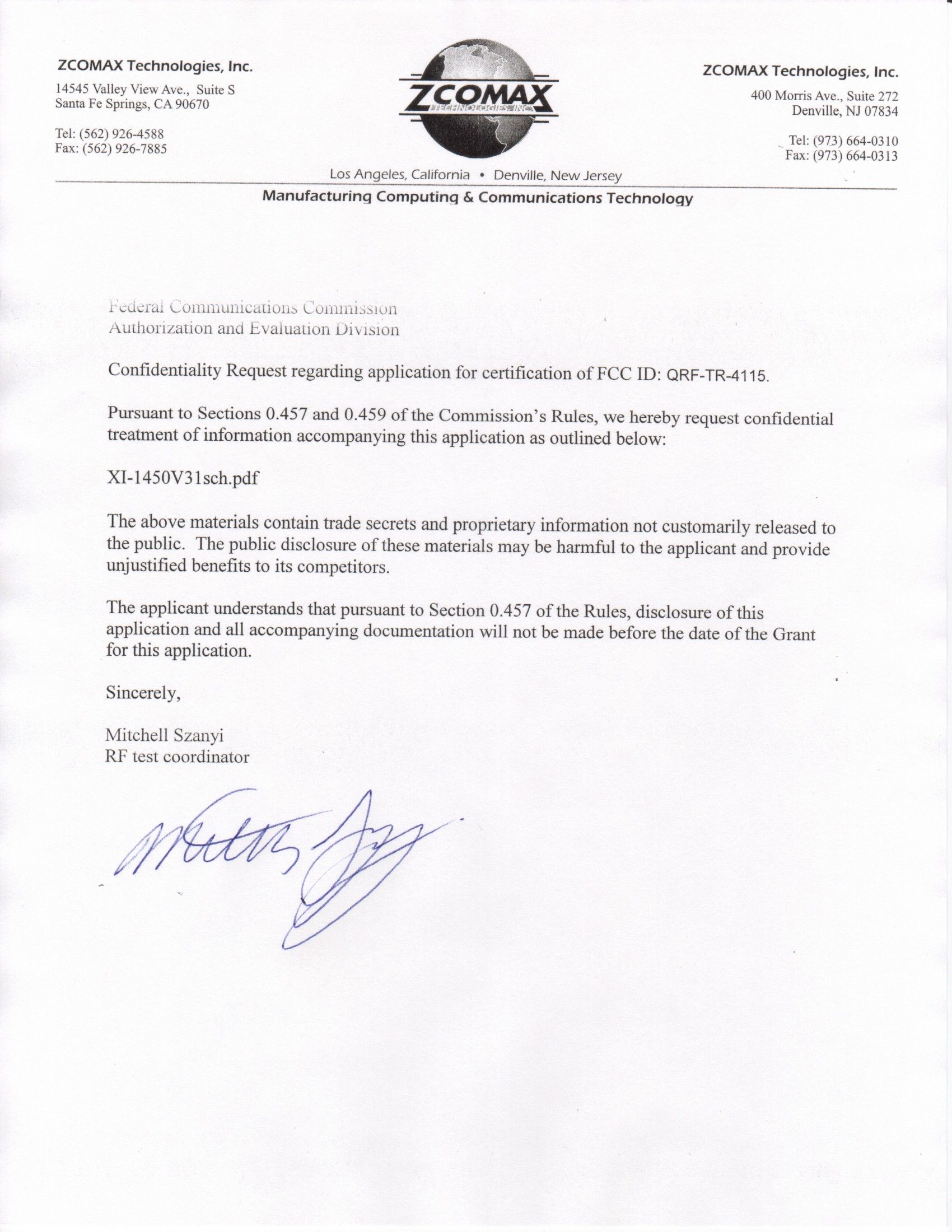
#13-11720 Stewart Crescent, Maple Ridge, BC, Canada V2X 9E7 T: 604.460.6002 F: 604-460.6005 Toll Free: 1-866-872-6936 Website: www.tranzeo.com Thursday, May 22, 2003 Federal Communications Commission 445 12th Street SW Washington, DC 20554 Re: Request for Confidentiality FCC ID: QRF-TR-3115 In accordance with FCC Rules part 0.459, we hereby request confidential treatment for the above referenced Certification application. The items to be held in confidence are: Confidential – TR-4115BlkDia.PDF The block Diagram of the TR-4115 Confidential – TR-4115IntPho.PDF Interior photos of the TR-3115 The application contains technical information that which ZComax and Tranzeo Wireless Technologies Inc. deem to be trade secrets and proprietary. If made public, the information might be used to the disadvantage of the applicant in the market place. Since the product is sealed and contains no user serviceable parts, the Interior Photos are only of use to the applicant’s competitors Thank you for your attention in this matter
External Photos
FCC Label Location TR 4115 - Front View TR 4115 Rear View Ethernet Connector Activity LED’s FCC LABEL
ID Label/Location Info
Tranzeo Wireless Technologies, Inc. 13 – 11720 Stewart Crescent Maple Ridge, BC Canada V2X 9E7 Ph: +1-604-460-6002 www.tranzeo.com 11 Mbps Wireless Access Point The firmware supplied with the TR-3115 is specific to Tranzeo Wireless Technologies Inc. and is the latest version. Only pre-approved and supplied upgrades are permitted. This device complies with Part 15 of the FCC Rules. Operation is subject to the following two conditions: (1) this device may not cause harmful interference, and (2) this device must accept any interference received, including interference that may cause undesired operation. TR 4115 FCC ID: QRF-TR-4115 Manufactured: May 24/2003 Serial #:TR20AA2089 F/W Version: 3.40.4 MAC Address: 00:60:B3:16:D9:DA
ID Label/Location Info
FCC Label Location TR 4115 - Front View
Operational Description
Operational Description EUT is a Wireless Router with 11 channels. This device provided four kind of transmitting speed 1,2,5.5 and 11Mbps. The device of RF carrier is DQPSK, DB PSK and CCK. The device adapts direct sequence spread spectrum modulation. This Broadband Wireless Router is an IEEE 802.11b Wireless LAN adapter. It allows your computer to connect to a wireless network and to share resources, such as files or printers without being bound to the network wires. Operation in 2.4GHz Direst Sequence Spread Spectrum (DSSS) radio transmission, the Broadband Wireless Router transfers data at speeds up to 64/128-bit Wired Equivalent Protection (WEP) algorithm is used. In addition, its standard compliance ensures that it can communicate with any 802.11b network.
Test Report
Protocol EMC FCC Compliance Test ReportFCC ID: QRF-TR-4115 Page 2 of 36 Table of Contents FCC PART 15 SUBPART B AND C COMPLIANCE TEST REPORT............................................ 1 Table of Contents ..................................................................................................................... 2 1.0GENERAL INFORMATION .................................................................................................. 4 1.1.EUT D ESCRIPTION .............................................................................................................. 4 1.2O PERATIONAL D ESCRIPTION ................................................................................................ 4 1.3T EST F ACILITIES .................................................................................................................. 5 1.4T EST S YSTEM D ETAILS ........................................................................................................ 5 1.5EUT M ODIFICATIONS ........................................................................................................... 5 1.6EUT T ESTING C ONFIGURATION ............................................................................................ 5 1.7T EST R ESULTS .................................................................................................................... 5 2.0CONDUCTED EMISSIONS .................................................................................................. 6 2.1 T EST E QUIPMENT ................................................................................................................ 6 2.2T EST S TANDARD .................................................................................................................. 6 2.3T EST S ETUP ........................................................................................................................ 6 2.4T EST L IMITS ........................................................................................................................ 6 2.5T EST R ESULTS .................................................................................................................... 7 2.5.1E MISSIONS P LOTS ............................................................................................................ 8 2.6T EST R ESULTS .................................................................................................................. 10 2.6.1E MISSIONS P LOTS .......................................................................................................... 11 3.0PEAK POWER OUTPUT.................................................................................................... 13 3.1T EST E QUIPMENT .............................................................................................................. 13 3.2T EST S ETUP ...................................................................................................................... 13 3.3L IMITS ...............................................................................................................................13 3.4T EST S TANDARD ................................................................................................................ 13 3.5T EST R ESULTS .................................................................................................................. 13 4.0RADIATED EMISSIONS..................................................................................................... 14 4.1T EST E QUIPMENT .............................................................................................................. 14 4.2T EST S ETUP ...................................................................................................................... 14 4.3T EST S TANDARD ................................................................................................................ 14 4.4L IMITS ...............................................................................................................................14 4.5T EST R ESULT .................................................................................................................... 15 4.6E MISSIONS P LOTS ............................................................................................................. 16 5.0RADIATED HARMONIC AND SPURIOUS EMISSIONS ................................................... 17 5.1T EST E QUIPMENT .............................................................................................................. 17 5.2T EST S ETUP ...................................................................................................................... 17 5.3T EST S TANDARD ................................................................................................................ 17 5.4L IMITS ...............................................................................................................................17 5.5T EST R ESULT C HANNEL 1 .................................................................................................. 18 5.6T EST R ESULT C HANNEL 6 .................................................................................................. 19 5.7T EST R ESULT C HANNEL 11 ................................................................................................ 20 6.0BAND EDGE....................................................................................................................... 21 6.1T EST E QUIPMENT .............................................................................................................. 21 6.2T EST S ETUP ...................................................................................................................... 21 6.3T EST S TANDARD ................................................................................................................ 21 6.4L IMITS ..................................................................…
Text truncated - open the document above for the full version.
Test Setup Photos
Protocol EMC FCC Compliance Test ReportFCC ID: QRF-TR-4115 Page 1 of 3 10.0 Test Photos Front Emissions Test Setup Protocol EMC FCC Compliance Test ReportFCC ID: QRF-TR-4115 Page 2 of 3 Rear Emissions Test Setup Protocol EMC FCC Compliance Test ReportFCC ID: QRF-TR-4115 Page 3 of 3 Conducted Emissions Setup
Contact Information
Applicant
Michael Rex(R&D Manager)
Test Firm
Protocol LabsRobert Stirling
Technical Specifications
| # | Rule Parts | Frequency Range | Power Output |
|---|---|---|---|
| 1 | 15C | 2.41 GHz - 2.46 GHz | 25.00 mW |
Other Applications from Tranzeo Wireless Technologies, Inc

QRF-G54DNT523
Mar 08, 20124.9GHz WIRELESS NETWORK ADAPTER
Equipment Class
TNB - Licensed Non-Broadcast Station Transmitter
QRF-FM58JD24UY
Jan 30, 20125.8 GHz WIRELESS BASE STATION
Equipment Class
DTS - Digital Transmission System
QRF-GNADX2NT4
May 24, 2011WIRELESS MESH ROUTER
Equipment Class
DTS - Digital Transmission System
QRF-PVE25XBY
Nov 16, 20102.5 GHz WIRELESS CPE
Equipment Class
TNB - Licensed Non-Broadcast Station TransmitterQRF-FMXLJD35UY
Feb 12, 2009Wireless Networking Device
Equipment Class
TNB - Licensed Non-Broadcast Station Transmitter