QRKHI469320UHF Long Range Reader
SAMSys Technologies, Inc.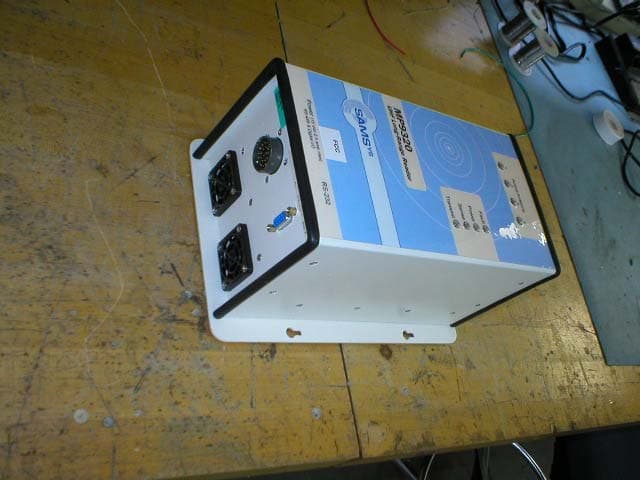
Click to zoom
Application Details
- Equipment Class
- DSS - Part 15 Spread Spectrum Transmitter
- Date of Grant
- Aug 21, 2003
- Application Purpose
- Original Equipment
- Date of Application
- Aug 20, 2003
- Equipment Note
- UHF Long Range Reader
- Frequency Range
- 903.10000000 - 926.90000000
- Company
- SAMSys Technologies, Inc.
- Country
- United States
Documents & Files
Document Text
Text extracted from the exhibit documents filed with the FCC. Open a document above to read the original.
Users Manual
Technical Installation and Calibration Guide MP9320 UHF Long-Range Reader Field Installation and Setup 2 First Edition (August 2003) © Copyright 2003 SAMSys Technologies, Inc. All Rights Reserved. Disclaimer and Limitation of Liability The content of this manual is for information use only and is subject to change without notice. SAMSys assumes no responsibility or liability for any errors or inaccuracies that may appear in this publication. No part of this manual may be reproduced in any form or by any means, electronic, mechanical, recording, or otherwise, without the prior written permission of SAMSys. SAMSys products are not designed, intended, authorized or warranted to be suitable for life support applications or any other life critical applications which could involve potential risk of death, personal injury, property damage, or environmental damage. About SAMSys SAMSys is the world leader in the design and supply of radio frequency identification (RFID) hardware solutions for high volume pallet and reusable container tracking applications in global logistics management, materials handling, and supply chain industries. SAMSys is a public company listed on the Canadian Venture Exchange under the symbol SMY. SAMSys Technologies, Inc. 44 East Beaver Creek Rd., Unit 11 Richmond Hill, Ontario L4B 1G8 Canada Phone: (905) 707-0404 Toll Free: (877) 463-6546 Fax: (905) 707-9944 E-mail: [email protected] Web: www.samsys.com Version 1.0, August 2003 3 Contents Introduction . . . . . . . . . . . . . . . . . . . . . . . . . . . . . . . . . . . . . 4 Assumptions . . . . . . . . . . . . . . . . . . . . . . . . . . . . . . . . . . . . 4 Getting Technical Assistance . . . . . . . . . . . . . . . . . . . . . . . 4 Antenna Installation . . . . . . . . . . . . . . . . . . . . . . . . . . . . . . . 5 Reader Mechanical Installation . . . . . . . . . . . . . . . . . . . . . . 7 Hollow Concrete Block Wall Mounting . . . . . . . . . . . . 8 Solid Concrete Wall Mounting . . . . . . . . . . . . . . . . . . . 9 Wood or Metal Wall Mounting . . . . . . . . . . . . . . . . . . . 9 Drywall Mounting . . . . . . . . . . . . . . . . . . . . . . . . . . . . . 9 Standalone Reader Communication Setup . . . . . . . . . . . . . 10 Standalone Reader Verification . . . . . . . . . . . . . . . . . . . . . . 11 Networked Reader Communication Setup . . . . . . . . . . . . . 12 Networked Reader Verification . . . . . . . . . . . . . . . . . . . . . . 13 Digital (TTL) Input/Output Setup . . . . . . . . . . . . . . . . . . . . 14 Digital I/O Overview . . . . . . . . . . . . . . . . . . . . . . . . . . . 14 Setting Digital Input for Reader Duty Cycle Control . . 15 Field Power Calibration . . . . . . . . . . . . . . . . . . . . . . . . . . . . 16 Transmit Power Reduction. . . . . . . . . . . . . . . . . . . . . . . . . . 17 4 Introduction This document is intended to assist technical service personnel engaged in the installation of the SAMSys MP9320 UHF Long-Range Reader. The document includes procedures for installing and configuring the reader to meet local standards and regulatory requirements. Topics and procedures presented in this document include the following: •Antenna Installation •Reader Mechanical Installation •Standalone Reader Communication Setup •Standalone Reader Verification •Networked Reader Communication Setup •Networked Reader Verification •Digital Input/Output Setup •Field Power Calibration •Transmit Power Reduction Assumptions This document is intended for technical personnel who are trained and experienced with the setup and configuration of SAMSys radio frequency identification systems including readers and antennas. Failure to correctly follow the procedures in this manual may result in faulty reader operation that violated regulatory requirements. Getting Technical Assistance If you need assistance or have questions related to the installation or use of this product, call or email SAMSys Technologies’ customer service department for support. [email protected] Telephone 1-877-367-4342 (toll free) 8:00am-6:00pm EST, Mon-Fri Fax1-919-281-1551 5 Antenna Installation The MP9320 supports from one to four external antennas in a variety of configurations. One- and two-antenna configurations are typical for most conveyor and container tracking. Four-antenna configurations are used for portals and loading dock doorways. Caution For uncontrolled environments (in the general population), the spacing between the antenna(s) and any persons must be at least 9 inches when the reader is operating at full power (4 Watts EIRP). To eliminate the spacing restriction, reduce the reader power to 3 Watts EIRP. Readers located in controlled access environments (occupational) have no spacing restrictions Figure 1–MP9320 Antenna Configurations 6 The MP9320 is factory calibrated for operation with the following type of antenna: The following antenna cable type is suggested: It is highly recommended that the antenna mounting be adjustable in order to obtain the best performance from the system. However, the antennas must be installed on a solid surface or frame to prevent damage or later misalignment. Perform the following to install the antennas. NOTE:Use the existing mounting holes on the antenna flange. Drilling new holes in the flange is not recommended. 1.Determine the location of each antenna. Ensure the antenna(s) will not be vulnerable to damage by moving inventory or equipment. 2.Use the antenna as a template and mark the mounting holes. 3.Drill and tap (if necessary) mounting holes for #10 or 1/4 inch mounting screws. For drywall mounting, use drywall anchors or toggle screws. 4.Mount each antenna and install the mounting screws. Do not overtighten the screws. Damage to the antenna case may result. 5.Route each antenna cable back to the reader location. For dual-opposing or portal configurations, route the opposing cables so they can not be damaged by equipment or personnel. 6.Secure each antenna cable with wire tie…
Text truncated - open the document above for the full version.
Users Manual
User’s Guide MP9320 UHF Long-Range Reader SAMSys MP9320 UHF Long-Range Reader Owner’s Manual First Edition (May 2003) © Copyright 2003 SAMSys Technologies, Inc. All Rights Reserved. Disclaimer and Limitation of Liability The content of this manual is for information use only and is subject to change without notice. SAMSys assumes no responsibility or liability for any errors or inaccuracies that may appear in this publication. No part of this manual may be reproduced in any form or by any means, electronic, mechanical, recording, or otherwise, without the prior written permission of SAMSys. SAMSys products are not designed, intended, authorized or warranted to be suitable for life support applications or any other life critical applications which could involve potential risk of death, personal injury, property damage, or environmental damage. About SAMSys SAMSys is the world leader in the design and supply of radio frequency identification (RFID) hardware solutions for high volume pallet and reusable container tracking applications in global logistics management, materials handling, and supply chain industries. SAMSys is a public company listed on the Canadian Venture Exchange under the symbol SMY. SAMSys Technologies, Inc. 44 East Beaver Creek Rd., Unit 11 Richmond Hill, Ontario L4B 1G8 Canada Phone: (905) 707-0404 Toll Free: (877) 463-6546 Fax: (905) 707-9944 E-mail: [email protected] Web: www.samsys.com Part Number: HI46932-01-OM-V1.2 Federal Communications Commission (FCC) Notice (Preliminary) This device was tested and found to comply with the limits set forth in Part 15 of the FCC Rules. Operation is subject to the following conditions: (1) this device may not cause harmful interference, and (2) this device must accept any interference received including interference that may cause undesired operation. These limits are designed to provide reasonable protection against harmful interference when the equipment is operated in a commercial environment. This device generates, uses, and can radiate radio frequency energy. If not installed and used in accordance with the instruction manual, the product may cause harmful interference to radio communications. Operation of this product in a residential area is likely to cause harmful interference, in which case, the user is required to correct the interference at their own expense. The authority to operate this product is conditioned by the requirements that no modifications be made to the equipment unless the changes or modifications are expressly approved by SAMSys Technologies. Trademarks SAMSys is a trademark of SAMSys Technologies, Inc. HyperTerminal is a registered trademark of Hilgraeve, Inc. Other company, product or service names appearing in this manual may be trademarks or service marks of their respective owners. MP9320 User’s Guide i Contents Chapter 1 – Introduction . . . . . . . . . . . . . . . . . . . . . . . . . . .1 Unpacking the Reader . . . . . . . . . . . . . . . . . . . . . . . . . . .2 About the MP9320 . . . . . . . . . . . . . . . . . . . . . . . . . . . . . .3 Physical Description . . . . . . . . . . . . . . . . . . . . . . . . . . . .5 Chapter 2 – Installation . . . . . . . . . . . . . . . . . . . . . . . . . . . .7 Antenna Installation . . . . . . . . . . . . . . . . . . . . . . . . . . . . .8 Reader Mechanical Installation . . . . . . . . . . . . . . . . . . . .11 Standalone Reader Communication Setup . . . . . . . . . . .13 Standalone Reader Verification . . . . . . . . . . . . . . . . . . . .14 Networked Reader Communication Setup . . . . . . . . . . .15 Networked Reader Verification . . . . . . . . . . . . . . . . . . . .16 Digital (TTL) Input/Output Setup . . . . . . . . . . . . . . . . . .17 Transmit Power Calibration . . . . . . . . . . . . . . . . . . . . . . .18 Chapter 3 – Operation . . . . . . . . . . . . . . . . . . . . . . . . . . . . .19 Reader Power Up . . . . . . . . . . . . . . . . . . . . . . . . . . . . . . .20 Reading Tags . . . . . . . . . . . . . . . . . . . . . . . . . . . . . . . . . .22 Operation with the ICCM . . . . . . . . . . . . . . . . . . . . . . . .23 Chapter 4 – Troubleshooting . . . . . . . . . . . . . . . . . . . . . . .25 General Troubleshooting . . . . . . . . . . . . . . . . . . . . . . . . .26 Contact Us . . . . . . . . . . . . . . . . . . . . . . . . . . . . . . . . . . . .28 Chapter 5 – Specifications . . . . . . . . . . . . . . . . . . . . . . . . . .31 Reader Specifications . . . . . . . . . . . . . . . . . . . . . . . . . . .32 Environmental Specifications . . . . . . . . . . . . . . . . . . . . .32 Power Supply Specifications . . . . . . . . . . . . . . . . . . . . . .33 RS-232 Connector Specifications . . . . . . . . . . . . . . . . . .33 Main I/O Connector Specifications . . . . . . . . . . . . . . . . .34 Antenna Specifications . . . . . . . . . . . . . . . . . . . . . . . . . .35 Antenna Cable Specifications . . . . . . . . . . . . . . . . . . . . .35 Regulatory Standards . . . . . . . . . . . . . . . . . . . . . . . . . . . .36 Appendix A – Reader Configuration . . . . . . . . . . . . . . . . .37 Operating Modes . . . . . . . . . . . . . . . . . . . . . . . . . . . . . . .38 Default Configuration . . . . . . . . . . . . . . . . . . . . . . . . . . .39 Changing Reader Configuration . . . . . . . . . . . . . . . . . . .40 MP9320 User’s Guide ii Figures MP9320 Reader and Accessories . . . . . . . . . . . . . . . . . .2 SAMSys Reader Network . . . . . . . . . . . . . . . . . . . . . . . .4 MP9320 LED Status Indicators . . . . . . . . . . . . . . . . . . . .5 MP9320 Active Antenna LED Indicators . . . . . . . . . . . .6 MP9320 End-Panel Connectors . . . . . . . . . . . . . . . . . . . .6 MP9320 Antenna Configurations . . . . . . . . . . . . . . . . . .8 MP9320 Reader Installations . . . . . . . . . . . . . . . . . . . . . .11 MP9320 Base Plate with Mounting Keyholes . . . . . . . . .12 MP9320 Standalone RS-232 Communication Setup . . . .13 MP9320 RS-485 Communication Se…
Text truncated - open the document above for the full version.
Users Manual
Reference Guide Comprehensive Heuristic Unified Messaging Protocol SAMSys Comprehensive Heuristic Unified Messaging Protocol Reference Guide First Edition (May 2003) © Copyright 2003 SAMSys Technologies, Inc. All Rights Reserved. Disclaimer and Limitation of Liability The content of this manual is for information use only and is subject to change without notice. SAMSys assumes no responsibility or liability for any errors or inaccuracies that may appear in this publication. No part of this manual may be reproduced in any form or by any means, electronic, mechanical, recording, or otherwise, without the prior written permission of SAMSys. SAMSys products are not designed, intended, authorized or warranted to be suitable for life support applications or any other life critical applications which could involve potential risk of death, personal injury, property damage, or environmental damage. About SAMSys SAMSys is the world leader in the design and supply of Radio Frequency Identification (RFID) hardware solutions for high volume pallet and reusable container tracking applications in global logistics management, materials handling, and supply chain industries. SAMSys is a public company listed on the Canadian Venture Exchange under the symbol SMY. SAMSys Technologies, Inc. 44 East Beaver Creek Rd., Unit 11 Richmond Hill, Ontario L4B 1G8 Canada Phone: (905) 707-0404 Toll Free: (877) 463-6546 Fax: (905) 707-9944 E-mail: [email protected] Web: www.samsys.com Part Number: HI471-CH-RF-V1.2 Trademarks SAMSys is a trademark of SAMSys Technologies, Inc. HyperTerminal is a registered trademark of Hilgraeve, Inc. Other company, product or service names appearing in this manual may be trademarks or service marks of their respective owners. Trademarks SAMSys is a trademark of SAMSys Technologies, Inc. HyperTerminal is a registered trademark of Hilgraeve, Inc. Tag-it TM is a trademark of Texas Instruments, Inc. Other company, product or service names appearing in this manual may be trademarks or service marks of their respective owners. CHUMP Reference Guide 1 Contents Chapter 1 - Introduction . . . . . . . . . . . . . . . . . . . . . 1 RFID Reader Programming Overview. . . . . . . . . . 2 Reader Operating Modes . . . . . . . . . . . . . . . . . . . . 2 Reader Programming . . . . . . . . . . . . . . . . . . . . . . . 3 What is an HDLC Protocol?. . . . . . . . . . . . . . . . . . 5 CHUMP Protocol Overview. . . . . . . . . . . . . . . . . . 8 CHUMP Frame. . . . . . . . . . . . . . . . . . . . . . . . . . . . 8 Message Head. . . . . . . . . . . . . . . . . . . . . . . . . . . . . 9 Command Block. . . . . . . . . . . . . . . . . . . . . . . . . . . 9 Message Tail. . . . . . . . . . . . . . . . . . . . . . . . . . . . . 10 Example CHUMP Commands . . . . . . . . . . . . . . . 11 CHUMP Notation Conventions . . . . . . . . . . . . . . 12 Chapter 2 - CHUMP Commands . . . . . . . . . . . . . 13 Command Format. . . . . . . . . . . . . . . . . . . . . . . . . 14 Reader Management Commands . . . . . . . . . . . . . 14 Tag Commands. . . . . . . . . . . . . . . . . . . . . . . . . . . 15 Flow Control Commands . . . . . . . . . . . . . . . . . . . 16 Parameter Descriptions. . . . . . . . . . . . . . . . . . . . . 17 Command Descriptions. . . . . . . . . . . . . . . . . . . . . 18 A . . . . . . . . . . . . . . . . . . . . . . . . . . . . . . . . . . . 18 Cr . . . . . . . . . . . . . . . . . . . . . . . . . . . . . . . . . . 19 Cw. . . . . . . . . . . . . . . . . . . . . . . . . . . . . . . . . . 20 Ht . . . . . . . . . . . . . . . . . . . . . . . . . . . . . . . . . . 21 Lb . . . . . . . . . . . . . . . . . . . . . . . . . . . . . . . . . . 22 Ld . . . . . . . . . . . . . . . . . . . . . . . . . . . . . . . . . . 23 Lf. . . . . . . . . . . . . . . . . . . . . . . . . . . . . . . . . . . 24 N . . . . . . . . . . . . . . . . . . . . . . . . . . . . . . . . . . . 25 Ra . . . . . . . . . . . . . . . . . . . . . . . . . . . . . . . . . . 26 Rd . . . . . . . . . . . . . . . . . . . . . . . . . . . . . . . . . . 27 Rf . . . . . . . . . . . . . . . . . . . . . . . . . . . . . . . . . . 28 CHUMP Reference Guide 2 Rn . . . . . . . . . . . . . . . . . . . . . . . . . . . . . . . . . . 29 Ro . . . . . . . . . . . . . . . . . . . . . . . . . . . . . . . . . . 30 Rt. . . . . . . . . . . . . . . . . . . . . . . . . . . . . . . . . . . 31 Ru . . . . . . . . . . . . . . . . . . . . . . . . . . . . . . . . . . 32 Rv . . . . . . . . . . . . . . . . . . . . . . . . . . . . . . . . . . 33 S . . . . . . . . . . . . . . . . . . . . . . . . . . . . . . . . . . . 34 Tm. . . . . . . . . . . . . . . . . . . . . . . . . . . . . . . . . . 35 Tr. . . . . . . . . . . . . . . . . . . . . . . . . . . . . . . . . . . 36 Ts . . . . . . . . . . . . . . . . . . . . . . . . . . . . . . . . . . 37 Tw. . . . . . . . . . . . . . . . . . . . . . . . . . . . . . . . . . 38 Wa. . . . . . . . . . . . . . . . . . . . . . . . . . . . . . . . . . 39 Wd. . . . . . . . . . . . . . . . . . . . . . . . . . . . . . . . . . 40 Wf. . . . . . . . . . . . . . . . . . . . . . . . . . . . . . . . . . 41 Wo. . . . . . . . . . . . . . . . . . . . . . . . . . . . . . . . . . 42 Wt . . . . . . . . . . . . . . . . . . . . . . . . . . . . . . . . . . 43 Yl . . . . . . . . . . . . . . . . . . . . . . . . . . . . . . . . . . 44 Ys . . . . . . . . . . . . . . . . . . . . . . . . . . . . . . . . . . 45 Chapter 3 - Reader Configuration . . . . . . . . . . . . 47 Reader Configuration Overview. . . . . . . . . . . . . . 48 Default Reader Configuration. . . . . . . . . . . . . . . . 49 Configuration Word Descriptions. . . . . . . . . . . . . 50 General Configuration Word (GCW). . . . . . . 50 Serial Configuration Word (SCW). . . . . . . . . 51 Serial Multidrop Address (SMA). . . . . . . . . . 53 Protocol Configuration Word (PCW). . . . . . . 53 Protocol Select Word (PSW) . . . . . . . . . . . . . 54 Specific Protocol Configurations . . . . . . . . . . 55 CHUMP Reference Guide 3 Chapter 4…
Text truncated - open the document above for the full version.
External Photos
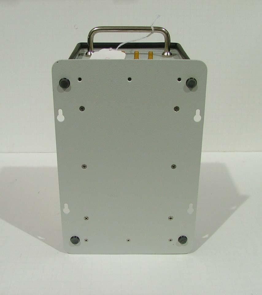
External View – Front – MP 9320 External View – Top/Left External View – Bottom/Right
ID Label/Location Info
Model MP9320 UHF Long-Range Reader This device complies with Par t 15 of the FCC Rules. Operation is subject to the following two conditions: (1) this device may not cause harmful interference, and (2) this device must accept any interference received, including interference that may cause undesired operation. FCC ID: QRKHI469320 THE POWER TO CHOOSE ! CANADA 210 IC: 4572A-MP9320
Internal Photos
Internal Photos – MP 9320 North America Board 1 – Component Side Board 1 – Solder Side Board 2 – Component Side Board 2 – Solder Side Board 3 – Component Side Board 3 – Solder Side Board 4 – Component Side – Shield in place Board 4 – Component Side – Shield removed Board 4 – Solder Side Enclosure Back/Heat Sink LED Indicator Board – Solder Side LED Indicator Board – LED side
Test Report
FREQUENCY HOPPING SEQUENCE The random frequency hop sequence was created using the random sequence generator found at http://www.random.org/sform.html , which generates true random numbers using atmospheric noise measurements. "The way the random.org random number generator works is quite simple. A radio is tuned into a frequency where nobody is broadcasting. The atmospheric noise picked up by the receiver is fed into a Sun SPARC workstation through the microphone port where it is sampled by a program as an eight bit mono signal at a frequency of 8KHz. The upper seven bits of each sample are discarded immediately and the remaining bits are gathered and turned into a stream of bits with a high content of entropy. Skew correction is performed on the bit stream, in order to ensure that there is an approximately even distribution of 0s and 1s. The skew correction algorithm used is based on transition mapping. Bits are read two at a time, and if there is a transition between values (the bits are 01 or 10) one of them - say the first - is passed on as random. If there is no transition (the bits are 00 or 11), the bits are discarded and the next two are read. This simple algorithm was originally due to Von Neumann and completely eliminates any bias towards 0 or 1 in the data." (from http://www.random.org/essay.html ) A "smallest value" of 0 and "largest value" of 129 were entered, corresponding to the 130 different frequencies we use, and the following random sequence was generated: 61, 7, 112, 60, 102, 35, 0, 122, 6, 66, 117, 69, 110, 78, 107, 9, 91, 59, 44, 121, 50, 126, 8, 24, 94, 19, 46, 127, 72, 114, 73, 68, 111, 56, 29, 86, 54, 120, 58, 118, 28, 125, 93, 52, 49, 115, 36, 129, 20, 3, 27, 74, 21, 113, 90, 106, 89, 47, 77, 57, 18, 75, 40, 80, 76, 17, 119, 11, 37, 105, 83, 48, 13, 82, 1, 10, 109, 4, 79, 2, 12, 43, 103, 32, 108, 67, 25, 45, 38, 53, 14, 34, 22, 116, 55, 26, 62, 99, 81, 71, 98, 70, 95, 128, 64, 88, 16, 84, 5, 41, 97, 23, 100, 31, 96, 51, 65, 104, 30, 101, 123, 87, 124, 42, 92, 63, 39, 15, 33, 85 . The active frequency is set sequentially from the above table. This results in a channel hop sequence of [61], [7], [112], [60], etc. where [xx] denotes a channel number. The resultant frequency hop sequence in MHz is 914.3, 903.5, 924.5, 914.1, etc. The sequence wraps around so that when on frequency [85], the NEXT frequency will be [61]. The raw table was scanned for adjacent frequencies, and if/when one was found, that index was moved further in the sequence until indices were no longer adjacent. The first and last five (5) channels in the table are not used by the hardware to avoid potential out of band interference levels. This allows for 120 total channels available for the hop sequence. When a blanked channel is selected in the table software will automatically step to the next valid channel on the list. This sequence is coded into a fixed HOP TABLE which is used by the software. This table is used to set frequencies, and index to the NEXT frequency in the sequence: Frequency (MHz) Channel Number Next Channel in Hop Sequence 902.100 0 122 902.300 1 10 902.500 2 12 902.700 3 27 902.900 4 79 903.100 5 41 903.300 6 66 903.500 7 112 903.700 8 24 Frequency (MHz) Channel Number Next Channel in Hop Sequence 903.900 9 91 904.100 10 109 904.300 11 37 904.500 12 43 904.700 13 82 904.900 14 34 905.100 15 33 905.300 16 84 905.500 17 119 905.700 18 75 905.900 19 46 906.100 20 3 906.300 21 113 906.500 22 116 906.700 23 100 906.900 24 94 907.100 25 45 907.300 26 62 907.500 27 74 907.700 28 125 907.900 29 86 908.100 30 101 908.300 31 96 908.500 32 108 908.700 33 85 908.900 34 22 909.100 35 0 909.300 36 129 909.500 37 105 909.700 38 53 909.900 39 15 910.100 40 80 910.300 41 97 910.500 42 92 910.700 43 103 910.900 44 121 911.100 45 38 911.300 46 127 911.500 47 77 911.700 48 13 911.900 49 115 912.100 50 126 912.300 51 65 912.500 52 49 912.700 53 14 912.900 54 120 913.100 55 26 913.300 56 29 913.500 57 18 913.700 58 118 913.900 59 44 Frequency (MHz) Channel Number Next Channel in Hop Sequence 914.100 60 102 914.300 61 7 914.500 62 99 914.700 63 39 914.900 64 88 915.100 65 104 915.300 66 117 915.500 67 25 915.700 68 111 915.900 69 110 916.100 70 95 916.300 71 98 916.500 72 114 916.700 73 68 916.900 74 21 917.100 75 40 917.300 76 17 917.500 77 57 917.700 78 107 917.900 79 2 918.100 80 76 918.300 81 71 918.500 82 1 918.700 83 48 918.900 84 5 919.100 85 61 919.300 86 54 919.500 87 124 919.700 88 16 919.900 89 47 920.100 90 106 920.300 91 59 920.500 92 63 920.700 93 52 920.900 94 19 921.100 95 128 921.300 96 51 921.500 97 23 921.700 98 70 921.900 99 81 922.100 100 31 922.300 101 123 922.500 102 35 922.700 103 32 922.900 104 30 923.100 105 83 923.300 106 89 923.500 107 9 923.700 108 67 923.900 109 4 924.100 110 78 Frequency (MHz) Channel Number Next Channel in Hop Sequence 924.300 111 56 924.500 112 60 924.700 113 90 924.900 114 73 925.100 115 36 925.300 116 55 925.500 117 69 925.700 118 28 925.900 119 11 926.100 120 58 926.300 121 50 926.500 122 6 926.700 123 87 926.900 124 42 927.100 125 93 927.300 126 8 927.500 127 72 927.700 128 64 927.900 129 20 FREQUENCY HOPPING DWELL TIMES The dwell time for the UHF Reader is designed for a range between 150 and 350 mS, based on the following software characteristics: 1. A millisecond counter is used to track time since the last hop. That is, at each hop, a counter is loaded with a constant number of milliseconds. At each millisecond time tick, the counter is decremented as long as it remains nonzero. The counter is preloaded with a value of 300. 2. When the reader has its field on but is not actively searching for tags, the software will hop whenever the counter becomes zero. A consistent time of 300 mS between hops in this situation has been verified. 3. When the reader is actively searching for tags, service delays and the need of tags for a stable field make it impractical to hop at precise time intervals. For this case the software follows a number of rules t…
Text truncated - open the document above for the full version.
Test Report
Project: 03CA18244 File: MC1884 Report: 030218 Date: July 12, 2003 Model: 9320 Release 1 RFID Reader (FCC ID: QRKHI46320) Test Report For FCC/Canada Compliance Samsys Technologies, Inc. Durham, NC USA Copyright 2003 Underwriters Laboratories Inc. Underwriters Laboratories Inc. authorizes the above-named company to reproduce this Report provided it is reproduced in its entirety. Project: 03CA18244 Underwriters Laboratories, Inc. Issued: 07/12/03 File: MC1884 Test Report on Electromagnetic Compatibility Page 2 of 64 FCC ID: QRKHI46320 Test Report: 030218 Test Report Details: Tests Performed By: Underwriters Laboratories Inc. 12 Laboratory Drive Research Triangle Park, NC 27709 Tests Performed For: Samsys Technologies, Inc. 2525 Meridian Parkway Lake Level Suite 60 Durham, NC 27713 USA Applicant Contact: Mr. Marv Baker (919) 281-1549 Test Report Number: 030218 Test Report Date: July 12, 2003 Product Type: RFID tag reader Model Number: 9320 Release 1 Sample Serial Number: Production Sample Sample Tag Number: S03LB25441 EUT Category: Transmitter - Low Powered EUT Type: Wall Mounted Sample Receive Date: June 17, 2003 Testing Start Date: June 24, 2003 Date Testing Complete: July 7, 2003 Underwriters Laboratories Inc. reports apply only to the specific samples tested under stated test conditions. All samples tested were in good operating condition throughout the entire test program. It is the manufacturer's responsibility to assure that additional production units of this model are manufactured with identical electrical and mechanical components. Underwriters Laboratories Inc. shall have no liability for any deductions, inferences or generalizations drawn by the client or others from Underwriters Laboratories Inc. issued reports. This report shall not be used to claim, constitute or imply product certification, approval, or endorsement by NVLAP, A2LA, or any agency of the US government. This report may contain test results that are not covered by the NVLAP or A2LA accreditation. The scope of accreditation is limited to the specific tests that are listed on the NVLAP and/or A2LA certificates provided at the end of this report. Project: 03CA18244 Underwriters Laboratories, Inc. Issued: 07/12/03 File: MC1884 Test Report on Electromagnetic Compatibility Page 3 of 64 FCC ID: QRKHI46320 Test Report: 030218 Summary of Testing: Test Test Name Comply Does Not See # Test Requirement/Specification Comply Remark 1 Conducted Emissions - Conducted Power X - 47 CFR Part 15, Subpart C / 47 CFR Part 15, Subpart C - Section 15.247 2 Conducted Emissions - Spurious Emissions X - 47 CFR Part 15, Subpart C / 47 CFR Part 15, Subpart C - Section 15.247 3 Radiated Emissions - Spurious Emissions and Restricted Bands X - 47 CFR Part 15, Subpart C / 47 CFR Part 15, Subpart C Sections 15.247 and 15.209 4 Radiated Disturbance Emissions - Occupied Bandwidth, Channel Spacing, etc X - 47 CFR Part 15, Subpart C / 47 CFR Part 15, Subpart C, Section 15.247 5 Radiated Disturbance Emissions - 30 to 1000 MHz Electric Field X - 47 CFR Part 15, Subpart B / 47 CFR Part 15, Subpart B, Class A 6 Conducted Disturbance Emissions - Voltage X - 47 CFR Part 15, Subpart B / 47 CFR Part 15, Subpart B, Class A 47 CFR Part 15, Subpart C / 47 CFR Part 15, Subpart C, Part 15.207 7 Radiated Disturbance Emissions - 1 to 40 GHz Electric Field X - 47 CFR Part 15, Subpart B / 47 CFR Part 15, Subpart B, Class A 8 Maximum Permissible Exposure X - 47 CFR Part 1 / 47 CFR Part 1.1307 Remarks: 1) Test Methods followed are consistent with ANSI C63.4:2001 where applicable 2) Modifications Required to Comply: None. 3) This unit is required to be professionally installed. Output power is determined during installation to compensate for antenna gain and cable loss. Antenna does not require unique antenna connectors because it is professionally installed. 4) Device is found to comply with FCC rules for a frequency hopping spread spectrum transmitter/receiver in Part 15.247. 5) Device is found to comply with Restricted Band rules in Part 15.209. 6) Compliance with Maximum Permissible Exposure requirements, OET Bulletin 65 Supplement C. Device is capable of power density in excess of FCC limits in the uncontrolled/general environment. Installation instructions specify minimum spacing for the actual EIRP of the installation. 7) EMC Sensitive components: Ferrite molded onto power cable (between AC-to-DC adapter and transmitter). 8) This report also satisfies requirements of the following similar Canadian standards: a. RSS-210 Low-Powered Unlicensed Radio Equipment b. RSS-102 RF Exposure Rules c. ICES-003 Interference from Digital Apparatus 9) Canadian Emissions Designator is determined to be: L1DBT101K. C The tests listed in the Summary of Testing section of this report have been performed and the results recorded by Underwriters Laboratories Inc. in accordance with the procedures stated in each test requirement and specification. The test list was determined by the Applicant as being applicable to the Equipment Under Test. As a result, the subject product has been verified to comply or not comply as noted in the Summary of Testing with each…
Text truncated - open the document above for the full version.
Contact Information
Applicant
Clifton D Morgan(Product Support Manager)
Technical Contact
SAMSys Technologies, Inc.Marvin Baker
[email protected]919-281-1549
2525 Meridian Parkway · Durham, North Carolina · United States
Non-Technical Contact
SAMSys Technologies, Inc.Ian Chalmers
ian/[email protected]919-281-1549
Test Firm
UL LLCRick Titus
Technical Specifications
| # | Rule Parts | Frequency Range | Power Output |
|---|---|---|---|
| 1 | 15C | 903.1 MHz - 926.9 MHz | 1 W |
Other Applications from SAMSys Technologies, Inc.
QRKH1469320
Jun 29, 2005MP9320 2.8 UHF 4-PORT RFID READER
Equipment Class
DSS - Part 15 Spread Spectrum Transmitter
QRKHI469310
Feb 08, 2005RFID Transmitter
Equipment Class
DSS - Part 15 Spread Spectrum Transmitter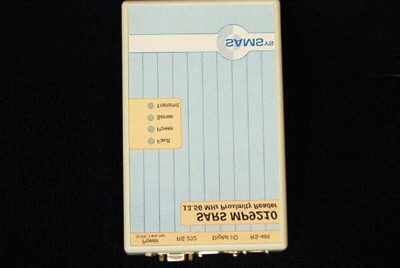
QRKHI469210
Jun 11, 2003High Frequency RFID Proximity Reader
Equipment Class
DXX - Part 15 Low Power Communication Device Transmitter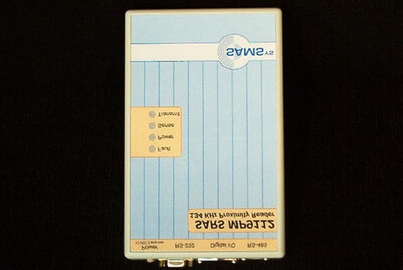
QRKHI469112
Apr 29, 2003SARS MP9112 134 kHz Proximity Reader
Equipment Class
DCD - Part 15 Low Power Transmitter Below 1705 kHz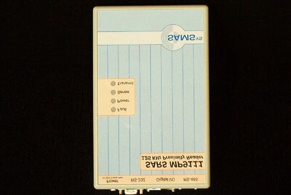
QRKHI469111
Apr 28, 2003SARS MP9111 125 kHz Proximity Reader
Equipment Class
DCD - Part 15 Low Power Transmitter Below 1705 kHz