QRZGPLDW004Ceiling Lamp
Goldpoint Int'l Limited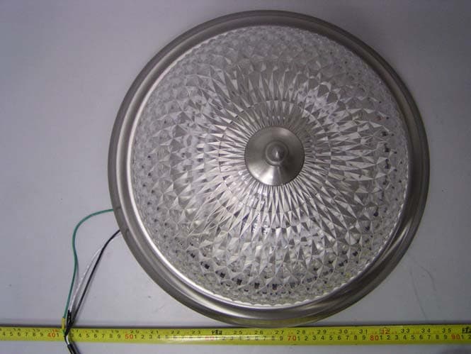
Click to zoom
Application Details
- Equipment Class
- 8CC - Part 18 Consumer Device
- Date of Grant
- Jun 10, 2004
- Application Purpose
- Original Equipment
- Date of Application
- Jun 10, 2004
- Equipment Note
- Ceiling Lamp
- Frequency Range
- 0.04000000 - 0.05000000
- Company
- Goldpoint Int'l Limited
- Country
- Hong Kong
Documents & Files
Document Text
Text extracted from the exhibit documents filed with the FCC. Open a document above to read the original.
Users Manual
INSTALLATION AND SAFETY INSTRUCTIONS FOR YOUR SAFETY WARNING : BE SURE THE ELECTROCITY TO THE WIRES YOU ARE WORKING ON IS SHUT OFF . EITHER THE FUSE IS REMOVED OR THE CIRCUIT BREAKER IS SHUT OFF . GENERAL You don’t need special tend to install this fixture . be sure to fellow the steps in the order given ,Under no clumsiness should a fixture be hung on house electrical wires . nor should a swag type fixture be installed on a ceiling while contains a swag type healing system , read instruction carefully . if you are unknown to how to present ,consult a qualified electrician . ASSEMBLY Carefully remove the fixture from the carton and check that all parts are included . as shown in Figure 1&2 . be careful not to misplace any of the screws or parts which are needed to install this fixture . STEP 1(if applicable ) Insert Fixing Bolt (3) with Connecting Bolt (9) through Base Nut (8) ,Base Nut Collar (7) and Base (6) , to make the Fixing Bolt protrude through the Base (6), then rotate Base Nut (8) to Fixing Bolt (3) clockwise ; STEP 2 (if applicable ) Install the lamp into Base (6) ; Step 3 Insert Fixing Bolt (12) through Fixing Rack (10) and the Key Slots, then tighten Fixing Nuts (11) on the Fixing Bolt (12) ; Step 4: Insert the protrusion of Fixing Bolt (3) of Base (6) through Cover (5) , Decoration (2) , then tighten Fixing Nut (1) ; INSTALLATION : IMPORTANT : DO NOT ATTACH FIXTURE DIRECTLY TO OUTLET BOX . STEP 1: Secure Fixing Rack (10) to outlet box with Fixing Bolt (12) (not supplied ) . Raised side to be see as illustrated . STEP 2: Thread fixture Fixing Bolt (12) into threaded holes of Fixing Rack (10) three turns each (see Fig 2) STEP 3 : A. Take notes of the color of the wire (s) on your fixture identity which group your fixture wire(s) falls into and connect the wires according to the directions below : Group a connector to black house wire Group a connector to white house wire Black White Parallel wire (round & smooth ) Parallel wire (square & ridged ) White or only with tracer White or only without tracer Brown , solo or black without tracer Brown, solo or black with tracer. NOTE when parallel wires need , the tracer wire is square shaped or ridged and the less tracer wire is round in shape of smooth , seen best when viewed from wire end .) to see tracer wires . grasp the end each wire and pull apart . B. take your fixture wire(s) from group and place every against the black wire to from the outlet box . DO NOT twist wires together before using wire connector . C. put a wire connector (not supplied ) into the wires and screw the connector clockwise Ground wire Wire connectors Fixing rack (10) Fixing bolt (12) NOT INCLUDED until you feel a firmness . D: Try gently to pull the connector off the wires , if you can pull the connector off , carefully re-do steps B and C, as above , and check again for a wire connection . E. Connect the fixture wires from group to the white wire from the outlet box in the same manner . STEP 4: GROUNDING INSTRUCTIONS : your fixture can be grounded in variety of different ways . choose the instructions below which apply to your fixture and follow directions carefully . NOTE : underwritten Lab does not require all fixtures to be grounded by using wire as long as other equivalent grounding means are provided These fixtures still meet all UL specifications . A. For fixtures with green grounding screws of mounting bar . the green grounding screw is to be inserted into the hole with two ** dimples provided on the Fixing Rack . wrap the ground wire from the fixture (if supplied ) and the ground wire from the outlet box (bare metal or green insulated wire ) around the green grounding screw the Fixing Rack in clockwise direction and tighten the screw . B. For fixtures with uninsulated wire on Fixing Rack , connect the ground wire from the fixture (if supplied )and the ground wire from the outlet box (bare metal or green insulated wire )to the insulated wire Fixing Rack using a small wire connector (not supplied ) C. For fixtures with uninsulated wire direct from fixture, connect the uninsulated wire from the fixture to the ground wire from the outlet box (bare metal or green insulated wire )using a small wire connector . FINAL ASSEMBLY Make sure no bare wires can be seen outside wire connector . STEP 1 : After wires are connected , took them carefully inside outlet box Raise the Base (6) to the ceiling allowing for Fixing Bolt(12)) to protrude through key slots(N) , rotate Base (6) clockwise Fixing Bolt (12) are in narrow part of key slot (N) , tighten screws (12) with screwdriver . STEP 2 : Install lamps STEP 3: Raise Cover (5) until it rests flush in Base (6) , Fixing Bolt (3) will protrude through Cover (5) STEP4: Through Fixing Bolt (3) insert Decoration (2) , secure in place with Fixing Nut (1) CLEANING To clean , wipe fixture with a soft cloth , clean glass with a mild soft cloth . Do not use abrasive material such as scouring pads or powders , steel wool or abrasive paper ORDERING PARTS Keep this sheet for fixture reference and in case you need to order replacement parts , all parts for this fixture can be ordered from picture of purchase , be sure to use exact wording from illustration when ordering parts . WARNING: 1. This device complies with Part 18 of the FCC Rules. 2. This product may cause interference to TV or other household equipment, and if these case occur, please move them far away from it. ● This product could produce interference when used near 0.7V, radio, wireless remote control or maritime safety communication equipment, or other critical navigation of communication equipment operating between 0.45---30 MHZ. If interference would occur, move the lamp away from the appliance a distance of three feet or more, Or plug the lamp or the appliance into a different outlet. ·This product complies with Part 18 of the FCC Rules but may cause interference to radios, television , wireless telephones, and remote controls. If interference occurs, move p…
Text truncated - open the document above for the full version.
External Photos
External Photos DW004-Top View DW004-Bottom View DW006-Top View DW006-Bottom View
ID Label/Location Info
ID Label Label FCC ID: QRZGPLDW004
ID Label/Location Info
ID Label/Location Label Location Information Specifications: Text is Black or white in color and is left justified. Labels are printed in indelible ink on permanent adhesive backing or silk-screened onto the EUT or shall be affixed at a conspicuous location on the EUT. Refer to the below arrow.
Internal Photos
Internal Photos DW004 - Uncovered View (1) DW004 - Uncovered View (2) DW004 - Inside View (1) DW004 - Inside View (2) DW004 - Inside View (3) DW004 - PCB View (1) DW004 -PCB View (2) DW004 -PCB View (3) DW004 -PCB View (4) DW006 - Uncovered View (1) DW006 - Uncovered View (2) DW006 - Inside View (1) DW006 - Inside View (2) DW006 -PCB View (1) DW006 -PCB View (2) DW006 -PCB View (3) DW006 -PCB View (4)
Parts List/Tune Up Info
GOLD POINT INT’L LIMITED ADD: 11 J,Daxin Building ,South Baoan Rd,Shenzhen TEL: 755-25577374/25568094 FAX:755-25576050 Electronic Ballast Electrical Rating Applicant: GOLD POINT INT’L LIMITED Product Name: Electronic Ballast Model: DW004 / DW006 Lamp Type: 3 PCES PLC LAMP 13W Components Type Rating 1 D1,D2,D3,D4 IN4007 1A/1KV 2 Z1 BZ55 4.3V/0.5W 3 D5 IN4148 1A/50V 4 T1,T2 S3N80 I DS =3A,V DSO ≥800V 5 R1 CR 110K Ω /0.25W 6 R2, R3 CR 10 Ω /0.25W 7 R4 CR 1KΩ/0.25W 8 E1 TRB 33uF /200V,105 °C 9 C5 TRB 22uF /25V,105 °C 10 C1 CL21 100 nF /250V,105 °C 11 C2, CT81BN 3.3 nF /1KV,105°C 12 C3 CT81BN 3.3nF/2KV,105 °C 13 C4 CBB81 2.2 nF/1.6KV,125 °C 14 C5,C7,C8 CBB81 820PF/1.6KV,125°C 15 L1 L N1 =L N2 =6.0mH,Size:19.5×19.5×18.5 Wire:N1:0.27mm,150turns N2:0.27mm,150turns 16 L3 L N1 =2.8mH,Size:19.5×19.5×18.5 Wire:N1:0.27mm,150turns 17 L2 L N3 =4.0mH,Size:28×34×25 Wire:N3:0.4mm,136turns 18 Enclosure Material Galvanized sheet steel
Schematics
1234 A B C D 4321 D C B A Title NumberRevisionSize A Date:4-Sep-2003 Sheet of File:C:\Documents and Settings\susanw\\120v-3x1.DDBDrawn By: C4 C3 TR1,2-4 R4 E2 D5 TR1,1-12 R2R3 TR1,9-7 TR1,7-10 TR1,6-11 C2 TR1,8-6 M2M1 L2 R1 E1 D4 D3 D2 D1 C1 Z1 C5C6 F1 L1 C7 120-3X13W REDREDYEL
Test Report
Note: This test report is specially limited to the use of the above client company and the product model only. It may not be duplicated without prior written consent of Bay Area Compliance Laboratory Corporation. This report must not be used by the client to claim product endorsement by NVLAP or any agency of the U.S. Government. FCC PART 18 ID MEASUREMENT AND TEST REPORT For GOLDPOINT INT’L LIMITED FLAT/RM A, 11/F, RITZ PLAZA, 122 AUSTIN RD, TSIMSHATSUI, KL, HONG KONG FCC ID: QRZGPLDW004 April 29, 2004 This Report Concerns: Original Report Equipment Type: Ceiling Lamp Test Engineer: Jandy Su Report Number RSH03073006 Test Date: April 28, 2004 Reviewed By: Ling Zhang Prepared By: Bay Area Compliance Lab Corp. ShenZhen Suite C, 41-D Electronics Science & Technology Building, No. 2070 Shennanzhong Rd ShenZhen, Guandong 518031, P.R. China Tel: 86-755- 83296449 Fax: 86-755- 83273756 GOLDPOINT INT’L LIMITED FCC ID: QRZGPLDW004 Report # RSH03073006.doc Page 2 of 10 FCC Part 18 ID Report TABLE OF CONTENTS GENERAL INFORMATION.......................................................................................................................................3 PRODUCT DESCRIPTION FOR EQUIPMENT UNDER TEST (EUT) ....................................................................................3 OBJECTIVE...................................................................................................................................................................3 RELATED SUBMITTAL(S)/GRANT(S).............................................................................................................................3 TEST METHODOLOGY..................................................................................................................................................3 TEST FACILITY.............................................................................................................................................................3 EXTERNAL CABLE........................................................................................................................................................4 SYSTEM TEST CONFIGURATION ..........................................................................................................................5 JUSTIFICATION.............................................................................................................................................................5 EQUIPMENT MODIFICATIONS.......................................................................................................................................5 CONFIGURATION OF TEST SYSTEM..............................................................................................................................5 TEST SETUP BLOCK DIAGRAM.....................................................................................................................................5 CONDUCTED EMISSION...........................................................................................................................................6 MEASUREMENT UNCERTAINTY....................................................................................................................................6 EUT SETUP..................................................................................................................................................................6 SPECTRUM ANALYZER SETUP......................................................................................................................................7 TEST EQUIPMENT LIST AND DETAILS...........................................................................................................................7 TEST PROCEDURE........................................................................................................................................................7 TEST DATA..................................................................................................................................................................8 PLOT(S) OF TEST DATA................................................................................................................................................8 GOLDPOINT INT’L LIMITED FCC ID: QRZGPLDW004 Report # RSH03073006.doc Page 3 of 10 FCC Part 18 ID Report GENERAL INFORMATION Product Description for Equipment Under Test (EUT) The GOLDPOINT INT’L LIMITED.’s model DW004, DW006 or the “EUT” as referred to in this report is a Ceiling Lamp which measures approximately in the table, rated input voltage: AC 120 V/60Hz. EUT Length (cm) Wide (cm) Height (cm) DW004 36.5 36.5 7.5 DW006 38.5 38.5 26.0 Note: Above two models have the same ballast, only the shape is different. * The test data gathered are from production sample, serial number: 030735, provided by the manufacturer. Objective The following test report is prepared on behalf of GOLDPOINT INT ’L LIMITED in accordance with Part 2, Subpart J, and Part 18, Subparts A, B, and C of the Federal Communication Commissions rules and regulations. The objective of the manufacturer is to determine compliance with FCC Part 18 limit requirements for Industrial, Scientific, and Medical Equipment Related Submittal(s)/Grant(s) No Related Submittals. Test Methodology All measurements contained in this report were conducted with MP-5, FCC Methods of Measurements of Radio Noise Emissions from ISM Equipment, February 1986. All radiated and conducted emissions measurement was performed at Bay Area Compliance Laboratory Corp. The radiated testing was performed at an antenna-to-EUT distance of 3 Meters. Test Facility Test site at Bay Area Compliance Laboratory Corporation has been fully described in reports submitted to the Federal Communication Commission (FCC) and Voluntary Control Council for Interference (VCCI). The details of these reports has been found to be in compliance with the requirements of Section 2.948 of the FCC Rules on February 1…
Text truncated - open the document above for the full version.
Test Setup Photos
Test Setup Photos DW004: Conducted Emission– Front View DW004: Conducted Emission– Side View DW006: Conducted Emission– Front View DW006: Conducted Emission– Side View
Contact Information
Applicant
Jennifer Lee(Representative)
Test Firm
Bay Area Compliance Laboratory Corp. (Shenzhen)John Chan
Technical Specifications
| # | Rule Parts | Frequency Range | Power Output |
|---|---|---|---|
| 1 | 18 | 0.04 MHz - 0.05 MHz | - |
Other Applications from Goldpoint Int'l Limited
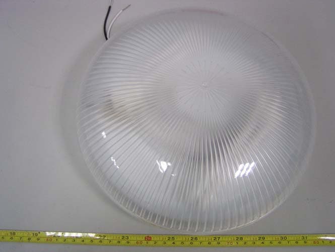
QRZGPLDW005
Jun 10, 2004Ceiling Lamp
Equipment Class
8CC - Part 18 Consumer Device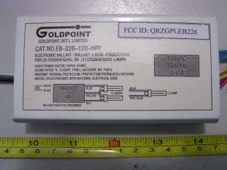
QRZGPLEB226
Dec 24, 2003Electronics Ballast
Equipment Class
8CC - Part 18 Consumer Device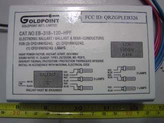
QRZGPLEB326
Dec 24, 2003Electronics Ballast
Equipment Class
8CC - Part 18 Consumer Device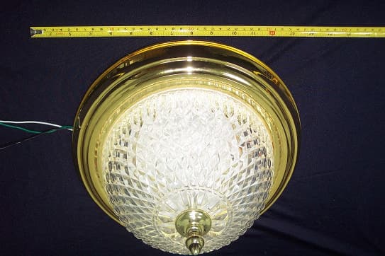
QRZGPL2013
Dec 18, 2002Electronic Ballast/Ceiling Lamp
Equipment Class
8CC - Part 18 Consumer Device