QRZGPLEB326Electronics Ballast
Goldpoint Int'l Limited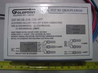
Click to zoom
Application Details
- Equipment Class
- 8CC - Part 18 Consumer Device
- Date of Grant
- Dec 24, 2003
- Application Purpose
- Original Equipment
- Date of Application
- Dec 24, 2003
- Equipment Note
- Electronics Ballast
- Frequency Range
- 0.00400000 - 0.00450000
- Company
- Goldpoint Int'l Limited
- Country
- Hong Kong
Documents & Files
Document Text
Text extracted from the exhibit documents filed with the FCC. Open a document above to read the original.
Users Manual
GOLDPOINT INTERNATIONAL LTD. ELECTRONIC BALLAST USER MANUAL FLUORESCENT LAMP BALLAST INSTALLATION INSTRUCTIONS Fluorescent ballast installation should only be attempted by persons familiar with electrical wiring procedures .If you lack knowledge of electrical wiring, you should have the ballast installed by a licensed electrician WARNING AND CAUTION Failure to mount and wire ballast and fixture in conformance with the National Electrical Code, applicable Provincial, Municipal codes, and the specific U.L. safety standards for the intended working environment may cause serious personal injury, death and/or property damage. During installation, power to ballast and fixture must be disconnected at all time. Ballast and fixture must also be grounded as a precaution against possible electrical shock. Never use in the following conditions: 1. Power supply with low voltage DC such as emergency light. 2. .Dimming circuit fixtures. 3. Where water may drop on the ballast. 4. Unsuitable for application when the ballast must be turned ON and OFF frequently. 5. Electronic ballast may use on a stable source of voltage that fluctuates in wide range-AC 110V-130V,50/60Hz. 6. Suitable for PLC fluorescent Lamp. 7. This product complies with Part 18 of the FCC Rules but may cause interference to radios, television, wireless telephones, and remote controls. If interference occurs, move product away from the device or plug either into a different outlet, or move the lamp out of the sight with the remote control receiver. 8. This product could produce interference when used near 0.7V, radio, wireless remote control or maritime safety communication equipment, or other critical navigation of communication equipment operating between 0.45---30 MHZ. If interference would occur, move the lamp away from the appliance a distance of three feet or more, Or plug the lamp or the appliance into a different outlet. INSTALLATION PROCEDURES 1、 The output wires are inserted into the sockets of lamps as per the diagram’s requirements. 2、 Make electrical connections using wire nuts. Use wiring diagram on ballast. CAUTION: To prevent shock hazard, leave no exposed wire beyond wire cut. 3、 Assemble fixture and install lamps. 4、 Turn power on at breaker and wall switch WIRING DIAGRAMS ALL BALLASTS MUST GROUNDED WHITE BLACK LAMP RED RED RED BALLAST LAMP LAMP ( 120VAC 50Hz/60Hz ) BLUE BLUE BLUE LINE WHITE BLACK LINE ( 120VAC 50Hz/60Hz ) BALLAST BLUE RED BLUE RED BLUE RED
External Photos
External Photos EB-326-120-HPF EUT- Front View EUT- Rear View EB-232-120-HPF EUT- Front View EUT- Rear View EB-318-120-HPF EUT- Front View EUT- Rear View
ID Label/Location Info
ID Label Label
ID Label/Location Info
ID Label/Location Label Location Information Specifications: Text is Black or white in color and is left justified. Labels are printed in indelible ink on permanent adhesive backing or silk-screened onto the EUT or shall be affixed at a conspicuous location on the EUT. Refer to the below arrow. EB-326-120-HPF EB-232-120-HPF EB-318-120-HPF
Internal Photos
Internal Photos EB-326-120-HPF EUT - View EUT -PCB View (1) EUT -PCB View (2) EUT -PCB View (3) EB-232-120-HPF EUT - View EUT -PCB View (1) EUT -PCB View (2) EUT -PCB View (3) EB-318-120-HPF EUT - View EUT -PCB View (1) EUT -PCB View (2) EUT -PCB View (3)
Test Report
Note: This test report is specially limited to the use of the above client company and the product model only. It may not be duplicated without prior written consent of Bay Area Compliance Laboratory Corporation. This report must not be used by the client to claim product endorsement by NVLAP or any agency of the U.S. Government. FCC PART 18 TEST MEASUREMENT AND TEST REPORT For GOLDPOINT INT’L LIMITED FLAT/RM A, 11/F, RITZ PLAZA, 122 AUSTIN RD, TSIMSHATSUI, KL, HONG KONG FCC ID: QRZGPLEB326 November 5, 2003 This Report Concerns: Original Report Equipment Type: Electronics Ballast Test Engineer: Jandy Su Report Number RSZ03092404 Test Date: November 4,2003 Reviewed By: Ling Zhang Prepared By: Bay Area Compliance Lab Corp. ShenZhen Suite C, 41-D Electronics Science & Technology Building, No. 2070 Shennanzhong Rd ShenZhen, Guandong 518031, P.R. China Tel: (755) 83296449 Fax: (755) 83273756 GOLDPOINT INT’L LIMITED FCC ID: QRZGPLEB326 Report # RSZ03092404.doc Page 2 of 11 FCC Part 18 ID Report TABLE OF CONTENTS 1 - GENERAL INFORMATION..................................................................................................................................3 1.1 PRODUCT DESCRIPTION FOR EQUIPMENT UNDER TEST (EUT) ..............................................................................3 1.2 OBJECTIVE.............................................................................................................................................................3 1.3 RELATED SUBMITTAL(S)/GRANT(S).......................................................................................................................3 1.4 TEST METHODOLOGY............................................................................................................................................3 1.5 TEST FACILITY.......................................................................................................................................................3 1.6 TEST EQUIPMENT LIST AND DETAILS.....................................................................................................................4 1.7 EXTERNAL I/O CABLING........................................................................................................................................4 2 - SYSTEM TEST CONFIGURATION.....................................................................................................................5 2.1 JUSTIFICATION.......................................................................................................................................................5 2.2 EQUIPMENT MODIFICATIONS.................................................................................................................................5 2.3 CONFIGURATION OF TEST SYSTEM.........................................................................................................................5 2.4 TEST SETUP BLOCK DIAGRAM...............................................................................................................................5 3 - CONDUCTED EMISSIONS TEST DATA............................................................................................................6 3.1 MEASUREMENT UNCERTAINTY..............................................................................................................................6 3.2 EUT SETUP............................................................................................................................................................6 3.3 SPECTRUM ANALYZER SETUP................................................................................................................................6 3.4 TEST PROCEDURE..................................................................................................................................................7 3.5 CONDUCTED EMISSIONS TEST DATA.....................................................................................................................7 3.6 TEST RESULT.........................................................................................................................................................8 3.7 PLOT(S) OF CONDUCTED EMISSIONS TEST DATA...................................................................................................8 GOLDPOINT INT’L LIMITED FCC ID: QRZGPLEB326 Report # RSZ03092404.doc Page 3 of 11 FCC Part 18 ID Report 1 - GENERAL INFORMATION 1.1 Product Description for Equipment Under Test (EUT) The GOLDPOINT INT’L LIMITED.’s model EB-326-120-HPF,EB-232-120-HPF,EB-318-120-HPF or the “EUT” as referred to in this report is a Electronics Ballast which measures approximately 13cm L x 8cm W x 3.5cm H, rated input voltage: AC 120 V/60Hz.The test data gathered are from the EUT described above, serial number 100111. This EUT was provided by the manufacturer as a representative manvfacturing sample. The test data gathered are from the EUT described above, serial number 100113; 100114; 100115. This EUT was provided by the manufacturer as a representative manvfacturing sample. 1.2 Objective The following test report is prepared on behalf of GOLDPOINT INT ’L LIMITED in accordance with Part 2, Subpart J, and Part 18, Subparts A, B, and C of the Federal Communication Commissions rules and regulations. The objective is to determine compliance with FCC rules. 1.3 Related Submittal(s)/Grant(s) No Related Submittals. 1.4 Test Methodology All measurements contained in this report were conducted with MP-5, FCC Methods of Measurements of Radio Noise Emissions from ISM Equipment, February 1986. All radiated and conducted emissions measurement was performed at Bay Area Compliance Laboratory Corp. The radiated testing was performed at an antenna-to-EUT distance of 3 Meters. 1.5 Test Facility The Open Area Test site used by Bay Area Compliance Laboratory Corporation to collect radiated and conducted emission measurement data is located in the back parking lot of the building …
Text truncated - open the document above for the full version.
Test Setup Photos
Test Setup Photos EB-326-120-HPF Conducted Emission– Front View Conducted Emission– Side View EB-318-120-HPF Conducted Emission– Front View Conducted Emission– Side View EB-232-120-HPF Conducted Emission– Front View Conducted Emission– Side View
Contact Information
Applicant
Jennifer Lee(Representative)
Test Firm
Bay Area Compliance Laboratory Corp. (Shenzhen)John Chan
Technical Specifications
| # | Rule Parts | Frequency Range | Power Output |
|---|---|---|---|
| 1 | 18 | 0.004 MHz - 0.0045 MHz | - |
Other Applications from Goldpoint Int'l Limited
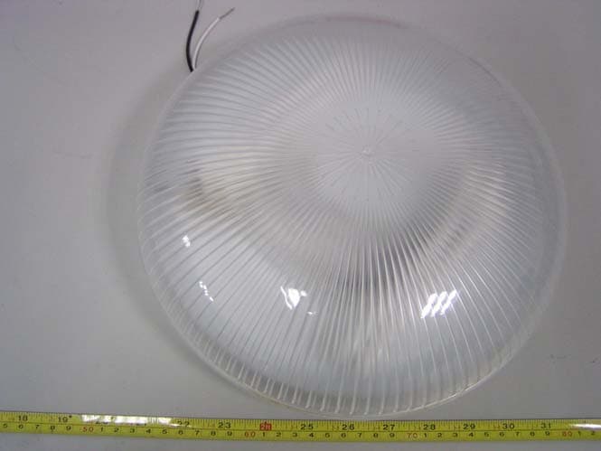
QRZGPLDW005
Jun 10, 2004Ceiling Lamp
Equipment Class
8CC - Part 18 Consumer Device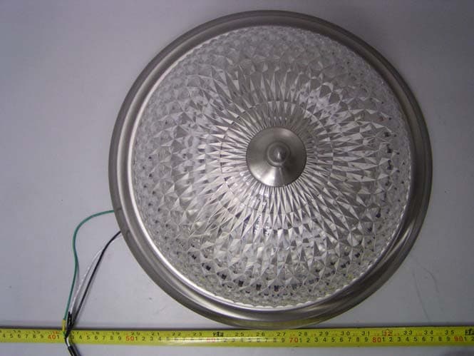
QRZGPLDW004
Jun 10, 2004Ceiling Lamp
Equipment Class
8CC - Part 18 Consumer Device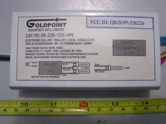
QRZGPLEB226
Dec 24, 2003Electronics Ballast
Equipment Class
8CC - Part 18 Consumer Device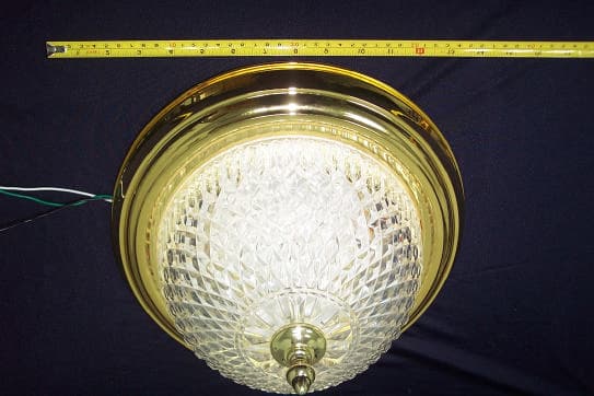
QRZGPL2013
Dec 18, 2002Electronic Ballast/Ceiling Lamp
Equipment Class
8CC - Part 18 Consumer Device