QS3WGSZR1USB STICK WLAN CARD
TwinMOS Technologies Inc.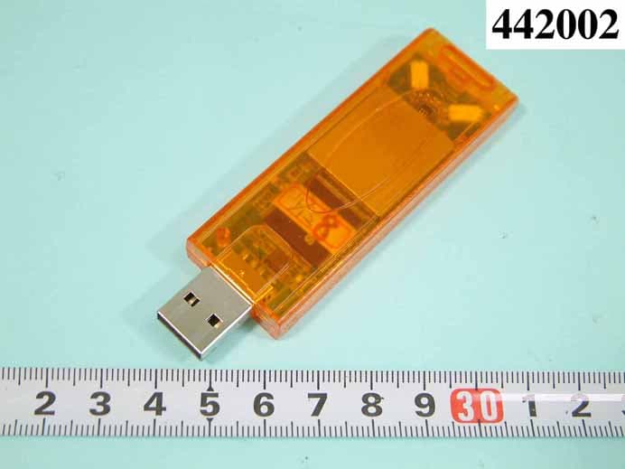
Click to zoom
Application Details
- Equipment Class
- DTS - Digital Transmission System
- Date of Grant
- Oct 31, 2004
- Application Purpose
- Original Equipment
- Date of Application
- Oct 31, 2004
- Equipment Note
- USB STICK WLAN CARD
- Frequency Range
- 2412.00000000 - 2462.00000000
- Company
- TwinMOS Technologies Inc.
- Country
- Taiwan
Documents & Files
Document Text
Text extracted from the exhibit documents filed with the FCC. Open a document above to read the original.
Users Manual
TwinMOS 802.11g Series G240 Wireless LAN Adapter User’s Manual TwinMOS ® G240 WLAN Card WWW.TwinMOS.COM Page 1 Contents PACKAGE CONTENTS...................................................................................2 INTRODUCTION...............................................................................................3 WIRELESS NETWORK OVERVIEW................................................................4 G240 WIRELESS NETWORK SCENARIOS...........................................6 INSTALLATION FOR WINDOWS (XP/2000/98SE).............................................9 CONFIGURATION UTILITY ...............................................................32 TROUBLESHOOTING...................................................................................50 TECHNICAL SPECIFICATIONS.....................................................................51 FCC CAUTION......................................................................................53 G240 WLAN Card WWW.TwinMOS.COM Page 2 PACKAGE CONTENTS Unpack your G240 WLAN adapter kit and verify that all items are present. z G240 Wireless LAN Adapter z User’s Manual (on CD) z Driver (on CD) z USB Cable If any of the items described appear to be damaged or missing, please contact your reseller. G240 WLAN Card WWW.TwinMOS.COM Page 3 INTRODUCTION The G240 WLAN adapter is a wireless network client that complies with the IEEE 802.11g standard on wireless LANs. The IEEE 802.11g standards compliance means this adapter gives you the flexibility to connect it to any 802.11g network. The IEEE 802.11g Ethernet standard allows you to connect computers and devices at speeds up to 11Mbps, dependent upon the distance between wireless adapters, the configuration of your working environment, or the capabilities or limitations of your computer systems. This G240 WLAN Adapter supports following WLAN features: z Automatic transmit data rate select mechanism in the transmit range of 1, 2, 5.5,6,9,11,12,18,24,36,48,54 and 11 Mbps. z Center frequency channel selection (2.4 GHz) z Roaming over multiple channels. z Supports USB interface z Supports power save mode z 128-bit Wired Equivalent Privacy (WEP) data encryption. z Plug and Play installation This G240 comes with software drivers for the most popular Microsoft Windows operating systems and can be integrated into a larger network, running Windows XP, Windows 2000, Windows ME, or Windows 98 in either Ad-Hoc mode or infrastructure mode. This manual provides a quick introduction to wireless technology and its application as it relates to networking. Take a moment to read through this manual and familiarize you with wireless technology. You should also give yourself some time to become familiar with your new wireless network. G240 WLAN Card WWW.TwinMOS.COM Page 4 WIRELESS NETWORK OVERVIEW A wireless local area network (LAN) is a flexible data communications system implemented as an extension to, or as an alternative for, a wired LAN. Using radio frequency (RF) technology, wireless LANs transmit and receive data over the air, minimizing the need for wired connections. Thus, wireless LANs combine data connectivity with user mobility. A local area network that transmit and receive over the air typically in an unlicensed frequency such as the 2.4GHz band. A wireless LAN does not require lining up devices for line of sight transmission like IrDA. Wireless access points (base stations) are connected to an Ethernet hub or server and transmit a radio frequency over an area of several hundred to a thousand feet which can penetrate walls and other nonmetal barriers. Roaming users can be handed off from one access point to another like a cellular phone system. Laptops use wireless modems that plug into an existing Ethernet port or that are self contained on PC cards, while stand-alone desktops and servers use plug-in cards (ISA, PCI, etc.). Wireless LANs offer the following productivity, convenience, and cost advantages over traditional wired networks: Mobility - WLAN provide LAN users to access data in any location within the operating range of the WLAN. Ad-hoc management decisions based on real-time information can significantly improve worker efficiency. Installation Speed and Simplicity - Installing a wireless LAN system can be fast and easy and can eliminate the need to pull cable through walls and ceilings. Installation Flexibility - Wireless technology allows the network to go where wire cannot go. Reduced Cost-of-Ownership - While the initial investment required for wireless LAN hardware can be higher than the cost of wired LAN hardware, overall installation expenses and life-cycle costs can be significantly lower. Long-term cost benefits are greatest in dynamic environments requiring frequent moves and changes. Scalability - Wireless LAN systems can be configured in a variety of topologies to meet the needs of specific applications and installations. Configurations are easily changed and range from peer-to-peer networks suitable for a small number of users to full infrastructure networks of thousands of users that enable roaming over a broad area. Installation Considerations Designed to go up to 300 feet (100 meters) indoors and up to 900 feet (273 meters) outdoors, G240 WLAN adapter lets you access your network from virtually anywhere you want. Keep in mind, however, that the number and thickness of walls, ceilings or other objects that the wireless signals must pass thru may limit range. Typical ranges vary depending on the types of materials and background RF noise in your home or business. The key to maximizing range is to follow these basic principles: G240 WLAN Card WWW.TwinMOS.COM Page 5 Keep the number of walls and ceilings between the access point and your receiving device to a minimum - Each wall or ceiling can reduce your TwinMOS G240 Wireless product’s range from 3-90 feet (1-30 meters.) For some businesses or for a large residential home deployment, it may be more beneficial to have more than …
Text truncated - open the document above for the full version.
External Photos
REPORT NO. : F442002 SPORTON International Inc. PAGE NUMBER : A1 OF A6 TEL : 886-2-2696-2468 ISSUED DATE : June 30, 2004 FAX : 886-2-2696-2255 APPENDIX A. Photographs of EUT REPORT NO. : F442002 SPORTON International Inc. PAGE NUMBER : A2 OF A6 TEL : 886-2-2696-2468 ISSUED DATE : June 30, 2004 FAX : 886-2-2696-2255
ID Label/Location Info
FCC ID: QS3WGSZR1 Label Location
ID Label/Location Info
49*18mm 導1.5R角 USB Stick WLAN Card Model:G240 IEEE 802.11g 2.4GHz /54Mbps FCC ID:QS3WGSZR1 Assembled >From Tested Components Complete system not tested Made in Taiwan MAC: 0470
RF Exposure Info
©2004 SPORTON International Inc..SAR Testing Lab This report shall not be reproduced except in full, without the written approval of Sporton. Rev.01 FCC SAR Test Report Test Report No ﹕ O442002-1-2-01 Specific Absorption Rate (SAR) Test Report for TwinMOS Technologies lnc. on the USB Stick Wireless LAN Card Report No. : O442002-1-2-01 Trade Name : TwinMOS Model Name : G240 FCC ID : QS3WGSZR1 Date of Testing : July 8, 2004 Date of Report. : July 9, 2004 Date of Review : July 9, 2004 The test results refer exclusively to the presented test model / sample only. Without written approval of SPORTON International Inc., the test report shall not be reproduced except in full. SPORTON International Inc. 6F, No.106, Sec. 1, Hsin Tai Wu Rd., Hsi Chih, Taipei Hsien, Taiwan, R.O.C. ©2004 SPORTON International Inc..SAR Testing Lab Tel:886-22696-2468 Fax:886-2-2696-2255 FCC SAR Test Report Test Report No ﹕ O442002-1-2-01 Table of Contents 1. Statement of Compliance .................................................................................................................................... 1 2. Administration Data............................................................................................................................................. 2 2.1. Testing Laboratory ..........................................................................................................2 2.2. Detail of Applicant ...........................................................................................................2 2.3. Detail of Manfacturer ......................................................................................................2 2.4. Application Detail ............................................................................................................2 3. Scope ................................................................................................................................................................... 3 3.1. Description of Device Under Test (DUT).........................................................................3 3.2. Product Photo.................................................................................................................4 3.3. Applied Standards: .........................................................................................................5 3.4. Device Category and SAR Limits ...................................................................................6 3.5. Test Conditons................................................................................................................6 3.5.1.Ambient Condition: ................................................................................................6 3.5.2.Test Configuration:.................................................................................................6 4. Specific Absorption Rate (SAR) .......................................................................................................................... 7 4.1. Introduction.....................................................................................................................7 4.2. SAR Definition ................................................................................................................7 5. SAR Measurement Setup .................................................................................................................................... 8 5.1. DASY4 E-Field Probe System ........................................................................................9 5.1.1.ET3DV6 E-Field Probe Specification ...................................................................10 5.1.2.ET3DV6 E-Field Probe Calibration ......................................................................10 5.2. DATA Acquisition Electronics (DAE) ............................................................................. 11 5.3. Robot ............................................................................................................................12 5.4. Measurement Server ....................................................................................................12 5.5. SAM Twin Phantom ......................................................................................................12 5.6. Data Storage and Evaluation ........................................................................................14 5.6.1.Data Storage........................................................................................................14 5.6.2.Data Evaluation ...................................................................................................14 5.7. Test Equipment List ......................................................................................................17 6. Tissue Simulating Liquids................................................................................................................................. 18 7. Uncertainty Assessment ................................................................................................................................... 20 8. SAR Measurement Evaluation .......................................................................................................................... 22 8.1. Purpose of System Performance check .......................................................................22 8.2. System Setup ...............................................................................................................22 8.3. Validation Results .........................................................................................................23 9. Description for DUT Testing Position ............................................................................................................... 24 10. Measurement Procedures .............................................................................................................................. 25 10.1. Spatial Peak SAR…
Text truncated - open the document above for the full version.
Test Report
FCC ID: QS3WGSZR1 Issued on June 30, 2004 Report No.: F442002 SPORTON International Inc. TEL : 886-2-2696-2468 FAX : 886-2-2696-2255 FCC TEST REPORT CATEGORY : Portable End Product PRODUCT NAME : USB Stick WLAN Card FCC ID. : QS3WGSZR1 FILING TYPE : Certification BRAND NAME : TwinMOS MODEL NAME : G240 APPLICANT : TwinMOS Technologies Inc. 303 No. 3, Tzu Chiang Rd, Hu Kou Xiang, Hsin Chu, Taiwan, R. O. C. MANUFACTURER : Same as Applicant ISSUED BY : SPORTON International Inc. 6F, No. 106, Sec. 1, Hsin Tai Wu Rd., Hsi Chih, Taipei Hsien, Taiwan, R.O.C. Statements: The test result in this report refers exclusively to the presented test model / sample. Without written approval of SPORTON International Inc., the test report shall not be reproduced except in full. Certificate or Test Report could not be used by the applicant to claim the product endorsement by CNLA, NVLAP or any agency of U.S. government. The test equipment used to perform the test are calibrated and traceable to NML/ROC or NIST/USA. Dr. Alan Lane Vice General Manager Sporton International Inc. Lab Code: 200079-0 FCC ID: QS3WGSZR1 Issued on June 30, 2004 Report No.: F442002 SPORTON International Inc. FCC ID. : QS3WGSZR1 TEL : 886-2-2696-2468 Page No. : i FAX : 886-2-2696-2255 Issued Date : June 30, 2004 Table of Contents History of this Test Report..................................................................................................................................ii 1. General Description of Equipment under Test.............................................................................................1 1.1. Applicant..........................................................................................................................................................................................1 1.2. Manufacturer ...................................................................................................................................................................................1 1.3. Basic Description of Equipment under Test ....................................................................................................................................1 1.4. Features of Equipment under Test..................................................................................................................................................1 1.5. Table for Carrier Frequencies .........................................................................................................................................................2 2. Test Configuration of the Equipment under Test.........................................................................................3 2.1. Description of the Test ....................................................................................................................................................................3 2.2. Frequency Range Investigated .......................................................................................................................................................3 2.3. Description of Test Supporting Units...............................................................................................................................................4 2.4. Connection Diagram of Test System ..............................................................................................................................................5 2.5. Test Software ..................................................................................................................................................................................6 3. Test Location and Standards .........................................................................................................................7 3.1. Test Location...................................................................................................................................................................................7 3.2. Test Conditions ...............................................................................................................................................................................7 3.3. Standards for Methods of Measurement .........................................................................................................................................7 3.4. DoC Statement................................................................................................................................................................................7 4. List of Measurements......................................................................................................................................8 4.1. Summary of the Test Results ..........................................................................................................................................................8 5. Test Result .......................................................................................................................................................9 5.1. Test of 6dB Spectrum Bandwidth....................................................................................................................................................9 5.2. Test of Maximum Peak Output Power ..........................................................................................................................................15 5.3. Test of Peak Power Spectral Density............................................................................................................................................17 5.4. Test of Band Edges Emission .......................................................................................................................................................23 5.5. Test of AC Power Line Conducted Emission ............................................................................................................................…
Text truncated - open the document above for the full version.
Test Setup Photos
1.1.1. Photographs of Conducted Emission Test Configuration z The photographs show the configuration that generates the maximum emission. FRONT VIEW REAR VIEW SIDE VIEW FRONT VIEW REAR VIEW
Contact Information
Applicant
Sam Hsu(Manager)
Test Firm
SPORTON International IncKathy Lin
Technical Specifications
| # | Rule Parts | Frequency Range | Power Output |
|---|---|---|---|
| 1 | 15C | 2.41 GHz - 2.46 GHz | 126.00 mW |
Other Applications from TwinMOS Technologies Inc.

QS3-BTTA01
Oct 01, 2006Bluetooth 2.1ch Audio System for iPod
Equipment Class
DSS - Part 15 Spread Spectrum Transmitter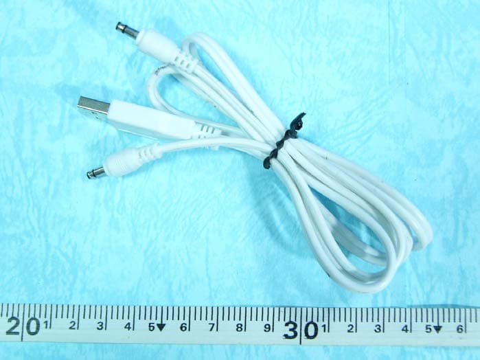
QS3BTT102
Feb 22, 2006Bluetooth Aduio Receiver
Equipment Class
DSS - Part 15 Spread Spectrum Transmitter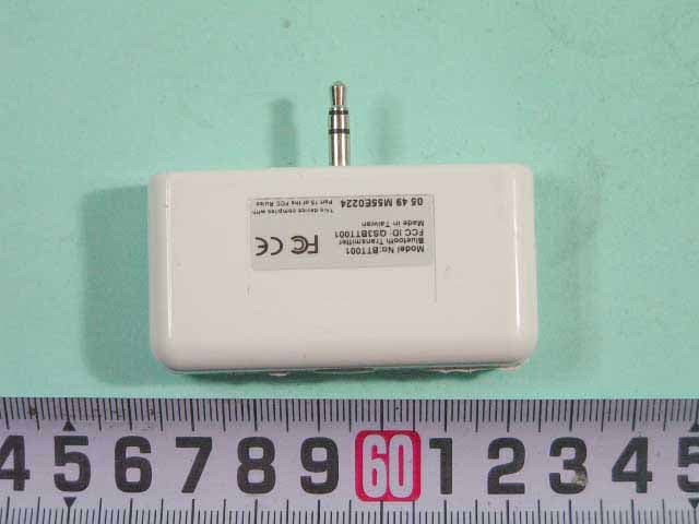
QS3BTT001
Dec 29, 2005Bluetooth Audio Transmitter
Equipment Class
DSS - Part 15 Spread Spectrum Transmitter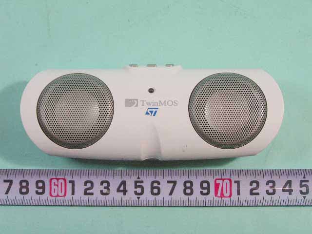
QS3BTT101
Dec 28, 2005Bluetooth Portable Speaker
Equipment Class
DSS - Part 15 Spread Spectrum Transmitter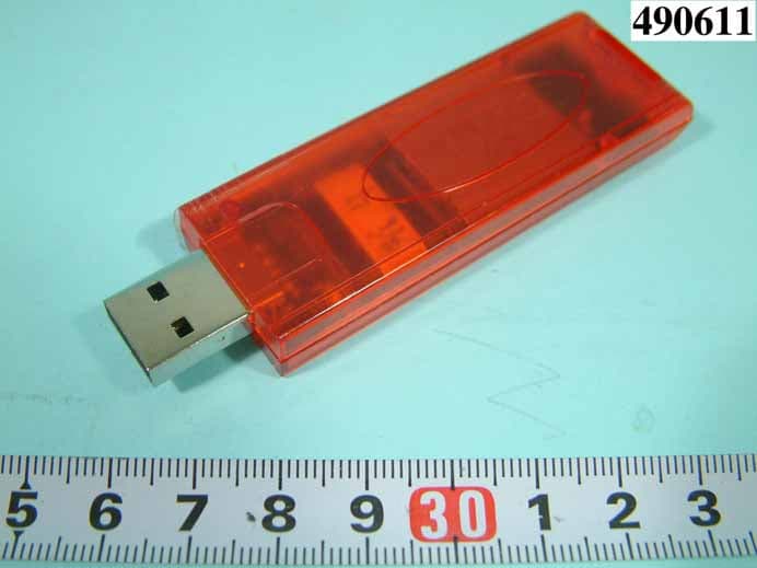
QS3WGSZB1
Oct 28, 2004WIRELESS LAN PRODUCT USB DONGLE
Equipment Class
DTS - Digital Transmission System