QS4-321AAccess Point
11 Wave Technology Inc.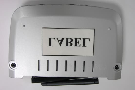
Click to zoom
Application Details
- Equipment Class
- DTS - Digital Transmission System
- Date of Grant
- Jun 02, 2003
- Application Purpose
- Original Equipment
- Date of Application
- Jun 02, 2003
- Equipment Note
- Access Point
- Frequency Range
- 2412.00000000 - 2462.00000000
- Company
- 11 Wave Technology Inc.
- Country
- Taiwan
Documents & Files
Document Text
Text extracted from the exhibit documents filed with the FCC. Open a document above to read the original.
Users Manual
WaveBuddy WLAN Access Point User Guide EWP-645WA1 Ve r s i o n 1 . 0 11Wave Techno logy Inc I INFORMATION TO USER Federal Communications Commission Statement This product has been tested and complies with the specifications for a Class B digital device, pursuant to Part 15 of the FCC Rules. These limits are designed to provide reasonable protection against harmful interference in a residential installation. The antenna used for this transmitter must be installed to provide a separation distance of least 20 centimeters from all persons and must operate in conjunction with other antenna or transmitters. This equipment generates, uses, and can radiate radio frequency energy and, if not installed and used according to the instructions, may cause harmful interference to radio communications. However, there is no guarantee that interference will not occur in a particular installation. If this equipment does cause harmful interference to radio or television reception, which is found by turning the equipment off and on, the user is encouraged to try to correct the interference by one or more of the following measures: ◇ Reorient or relocate the receiving antenna ◇ Increase the separation between the equipment or device ◇ Connect the equipment to an outlet other than receiver’s ◇ Consult a dealer or an experienced radio/TV technician for assistance Notice: The Part 15 radio device operates on a non-interference basis with other devices operating at this frequency. Any change or modification not expressly approved by the party responsible could void the warranty. Regulatory The wireless LAN Card must be installed and used in strict accordance with the manufacturer’s instructions. This device complies with the following radio frequency and safety standards. USA - Federal Communications Commission (FCC) This device complies with Part 15 of FCC Rules. Operation is subject to the following two conditions: 1. This device may not cause harmful interference 2. This device must accept any interference that may cause undesired operation Europe - R&TTE Directive This device complies with the specifications listed below: ⌧ ETS 300-826 General EMC requirements for Radio equipment ⌧ETS 300-328 Technical requirements for Radio equipment ⌧ EN60950 Safety requirements for Radio equipment EU Countries not intended for use The ETSI version of this device is intended for home and office use in Austria, Belgium, Denmark, Finland, France (with Frequency channel restrictions). Germany, Greece, Ireland, Italy, Luxembourg, Netherlands, Portugal, Spain, Sweden and United Kingdom. The ETSI version of this device is also authorized for use in EFTA member states Iceland, Liechtenstein, Norway and Switzerland. 11Wave Techno logy Inc II Table of Contents Section 1. Introduction.................................................................................................................1 1.1 The WaveBuddy WLAN Access Point ......................................................................................1 1.2 Package Contents .......................................................................................................................1 1.3 System Requirements.................................................................................................................1 1.4 Features .. ...................................................................................................1 1.4.1 Firmware Features................................................................................................................1 1.4.2 Bridging Functions ...............................................................................................................2 1.4.3 Management .........................................................................................................................2 1.4.4 Roaming ...............................................................................................................................2 1.4.5 Operation Modes ..................................................................................................................2 1.5 Network Interface ......................................................................................................................2 Section 2. Network Configuration and Planning.......................................................................3 2.1 Wireless LAN Basic...................................................................................................................3 2.2 Network Topology .....................................................................................................................3 Section 3. Installation Overview..................................................................................................6 Section 4. Setting the IP Address of the Access Point ..............................................................11 4.1 Using the Ethernet Port/Wireless Port .....................................................................................11 4.1.1 Using ARP/Ping commands ...............................................................................................11 4.1.2 DHCP client .......................................................................................................................12 4.2 Using the USB Port..................................................................................................................12 Section 5. Access Point Configuration ......................................................................................14 5.1 Using the SNMP Configuration Utility application .................................................................14 5.1.1 Connecting to the Access Point ..........................................................................................14 5.1.2 Configuring the Access Point .............................................................................................16 5.1.3 Reset the AP by manual................…
Text truncated - open the document above for the full version.
ID Label/Location Info
Label Format & Position Size:67 x 35 mm
Operational Description
OPERATION DESCRIPTION for Access Point Project name : 11WA-321A 1: T/R switch: a: TX or RX multiplexing switch, TX/RX are half duplex. B: Antenna A or B switch. 2: RF5117 : 2.4GHz Power Amplifier RF5117 is a linear, medium-power, high-efficiency amplifier IC designed specifically for battery-powered WLAN applications .The devices manufactured on an advanced Gallium Arsendie Heterojunction Bipolar Transistor(HBT) process, and has been designed for use as the Final RF amplifier in 2.5GHz WLAN and other spread-spectrum transmitters. The device is provider in a 3mmX3mm, 16 pin, leadless chip carrier with a backside ground. The RF5117 is designed to maintain linearity over a wide range of supply voltage and power output. RF5117 requires only a single positive supply of 3.0V nominal(or greater) to operate to full specifications. Power control is provided through two bias control input pins (Vreg1 and Vreg2). External matching on the input and output . Both the input and the output of the device need a series DC-blocking capacitor. Capacitor used as a matching component can also serve as the blocking Cap. Features: --Single 3.3V Power Supply --+20.08dBm Saturated Output Power --26dB Small Signal Gain 3: RF2948 2.4GHz SPREAD-SPECTRUM TRANSCEIVER RF2948 is a monolithic integrated circuit specifically designed for Direct-sequence spread-spectrum systems operating in a 2.4GHz ISM band. The part include: a direct conversion from IF receiver With variable gain control; quadrature demodulator; I/Q baseband amplifier, and on chip programmable baseband filter. For the transmit side, a QPSK modulator and the upconverter are provided. The design reuses the IF SAW filter for transmit and receive deducing the number of SAW filters required. RF2948 is also designed to be of a 2.4GHz chipset consisting of the RF2494 LNA/Mixer. Features: --45MHz to 500MHz IF Quad Demod --On-chip Variable Baseband Filters --Quadrature Modulator and Upconverter --2.7V to 3.6V Operation --2.4GHz PA Driver 4: RF2494 : HIGH FREQUENCY LNA/MIXER RF2494 is a monolithic integrated UHF receiver front end suitable for 2.4GHz ISM band applications. The IC contains all of the required components to implement the RF functions of the receiver except for the passive filtering and LO generation. It contains an LNA, a second RF amplifier and a doubly balanced mixer. The output of the LNA is made available as an output to permit the insertion of a bandpass filter between the LNA and the RF/Mixer section. The mixer outputs can beselectively disabled to allow for the IF filter to be used in the transmit mode. The cascaded power gain of the LNA/Mixer is 29dB, which after insertion loss in the image filter(`3dB) and IF SAW filter(~1-dB), still gives 16dB of gain prior to the IF Amps. Because of this, the noise figure of the IF Amps should not significantly degrade system noise figure. Features: --Single 2.7V to 3.6V Power Supply. --2400MHz to 2500MHz Operation. --Two Gain setting: 28dB or 12dB. --4.5dB Cascaded NF, high Gain Mode. --20mA DC Current Consumption --Input IP3: -23dBm or –8dBm 5: RF3000 : SPREAD-SPECTRUM BASEBAND MODEM RF3000 is a monolithic CMOS baseband processor. It is suitable for use in 11Mbps IEEE802.11b wireless LNA systems and general purpose ISM band radios, and contains all functions required to convert a spread-spectrum signal to bit stream. PN code lengths up to 64 bits allows increased processing gain. The on-chip equalizer provides protection against multi-path in the data rate modes. All functions are configurable via SPI port. A complete 2.4GHz radio reference design is available from RFMD.RF300 receiver port provides a clear channel assessment(CCA) to the MAC and supports PSK and CCK DSSS mode. Features: --On-chip ADCs and DACs, RSSI, AGC --BPSK/QPSK/CCK --250ns Dealy spread Equalizer --Supports Antenna Diversity --PN Sequences Up To 64Bits Long 6: AT76C510 Wireless to Ethernet Bridge (VNET-B) VNET-B is the internetworking device for interconnecting a Wireless LAN with other Wireless LANs(WLAN) and legacy LANs.VNET-B based bridges act as Access Points(AP) to the WLAN and communicate packets that are destined outside the WLAN using IP over Ethernet. In case the WLAN user is mobile, roaming functions are also supported at the VNET-B bridges. The data transactions over this unified environment are categorized according to the type of end-to-end device: End stations transactions When two end stations communicate (irrespective to the type of network they belong) Inter-networking device transactions The VNET-B device implements all necessary communication protocols for supporting inter-networking functions, implements logical grouping of users independent of their physical location and provides secure links by implementing encryption algorithms. 7: REALTEK SINGLE CHIP SINGLE PORT 10/100M FAST ETHERNET PHYCEIVER RTL8201BL The RTL8201BL is a single-port Phyceiver with an MII (Media Independent Interface)/SNI(Serial Network Interface). It implements all 10/100M Ethernet Physical-layer functions including the Physical Coding Sublayer (PCS), Physical Medium Attachment (PMA), Twisted Pair Physical Medium Dependent Sublayer (TP-PMD), 10Base-Tx Encoder/Decoder and Twisted Pair Media Access Unit (TPMAU). A PECL interface is supported to connect with an external 100Base- FX fiber optical transceiver. The chip is fabricated with an advanced CMOS process to meet low voltage and low power requirements. The RTL8201BL can be used as a Network Interface Adapter, MAU, CNR, ACR, Ethernet Hub, Ethernet Switch. Additionally, it can be used in any embedded system with an Ethernet MAC that needs a twisted pair physical connection or fiber PECL interface External 100Base-FX optical transceiver module.
RF Exposure Info
Training Research Co., Ltd. 255 Nanyang Street, Shijr, Taipei Hsien 221, Taiwan, R.O.C. TEL: 886-2-26935155 FAX: 886-2-26934440 TRCSince1985 ® Measurement of MPE 1. Foreword In adopt with the Human Exposure IEEE C95.1, and according to the FCC 1.1310. The Maximum Permissible Exposure (MPE) is obligated to measure in order to prove the safety of radiation harmfulness to the human body. The Gain of the antenna used is measured in an Anechoic chamber. The maximum total power to the antenna is to be recorded. By adopting the Friis Transmission Formula and the power gain of the antenna, we can find the distance right away from the product, where the limit of the MPE is. 2. Description of EUT Applicant : 11Wave Technology Inc., Applicant Address : No. 6 Lane35 jihu Rd., Neihu, Taipei, Taiwan 114, R.O.C. Classification : Mobile Device (i) Under normal use condition, the antenna is at least 20cm away from the user; (ii) Warning statement for keeping 2.5cm separation distance and the prohibition of operating next to the person has been printed in the user’s manual Model No. : PWA-645, 11WA321A-, 11WA-321AXXXX (X : 0~9, A~Z, a~z, Blank), GWA-23B Granted FCC ID : QS4-321A Frequency Range : 2.412 GHz ~ 2.462GHz Support Channel : 11 Channel Modulation Skill : BPSK, QPSK, CCK Power Type : By the Power Adaptor Training Research Co., Ltd. 255 Nanyang Street, Shijr, Taipei Hsien 221, Taiwan, R.O.C. TEL: 886-2-26935155 FAX: 886-2-26934440 TRCSince1985 ® 3. Limits for Maximum Permissible Exposure (MPE) Frequency Range (MHz) Electric Field Strength (V/m) Magnetic Filed Strength (H) (A/m) Power Density (S) (mW/cm2) Averaging Time |E| 2 , |H| 2 or S (minutes) (A) Limits for Occupational/Controlled Exposure 0.3-3.0 614 1.63 100 6 3.0-30 1842/f 4.89/f 900/f 2 6 30-300 61.4 0.163 1.0 6 300-1500 -- -- f/300 6 1500-100,000 -- -- 5 6 (B) Limits for General Population/Uncontrolled Exposure 0.3-1.34 614 1.63 100 30 1.34-30 824/f 2.19/f 180/f 2 30 30-300 27.5 0.073 0.2 30 300-1500 -- -- f/1500 30 1500-100,000 -- -- 1.0 30 [The EUT is tested in transmit and receive modes and in the first, middle and the last channel separately. The following shows only our observation have the greatest emissions.] According to OET BULLETIN 56 Fourth Edition/August 1999, Equation for Predicting RF Fields: Friis Transmission Formula: 2 22 /233.0 )5.2(4 18.009.102 4 cmmW R PG S ππ × == Estimated safe separation: cm PG R209.1 4 18.009.102 4 = × == ππ Remarks: "The safe estimated separation that the user must maintain from the antenna is at least 1.890 cm." Where: S = power density (in appropriate units, e.g. mW/cm2) P = power input to the antenna (in appropriate units, e.g., mW) G = power gain of the antenna in the direction of interest relative to an isotropic radiator R = distance to the center of radiation of the antenna (appropriate units, e.g., cm) The Numeric gain G of antenna with a gain specified in dB is determined by: G = Log -1 (dB antenna gain/10) G = Log -1 (1.8 / 10) = 0.18
Test Report
Test Report ---------------------------------------------------------------------------- 1/41 Report No.: W2615473, FCC Part 15 Training Research Co., Ltd., TEL: 886-2-26935155, Fax: 886-2-26934440 MEASUREMENT REPORT of Access Point Applicant : 11Wave Technology Inc. Model No. : PWA-645, 11WA-321A, 11WA-321AXXXX (X : 0~9, A~Z, a~z, Blank), GWA-23B EUT : Access Point FCC ID : QS4-321A Report No. : W2615473 Tested by : Training Research Co., Ltd. TEL : 886-2-26935155 FAX : 886-2-26934440 No. 255, Nanyang Street, Shijr, Taipei Hsien 221, Taiwan, R.O.C. Test Report ---------------------------------------------------------------------------- 2/41 Report No.: W2615473, FCC Part 15 Training Research Co., Ltd., TEL: 886-2-26935155, Fax: 886-2-26934440 CERTIFICATION We here by verify that: The test data, data evaluation, test procedures and equipment configurations shown in this report were made mainly in accordance with the procedures given in ANSI C63.4 (1992) as a reference. All test were conducted by Training Research Co., Ltd., 255 Nanyang Street, Shijr, Taipei Hsien 221, Taiwan, R.O.C. Also, we attest to the accuracy of each. We further submit that the energy emitted by the sample EUT tested as described in the report is in compliance with the technical requirements set forth in the FCC Rules Part 15 Subpart B (Declaration of Conformity) and C Section 15.247. Applicant : 11Wave Technology Inc. Applicant address : 3F, No. 6 Lane 35, jihu Rd., Neihu, Taipei, Taiwan R.O.C. EUT : Access Point Model No. : PWA-645, 11WA-321A, 11WA-321AXXXX (X : 0~9, A~Z, a~z, Blank), GWA-23B FCC ID : QS4-321A Report No. : W2615473 Test Date : April 17, 2003 Prepared by: Approved by: Jack Tsai Frank Tsai Tested by : Training Research Co., Ltd. TEL: 886-2-26935155 FAX: 886-2-26934440 255 Nanyang Street, Shijr, Taipei Hsien 221, Taiwan, R.O.C. Test Report ---------------------------------------------------------------------------- 3/41 Report No.: W2615473, FCC Part 15 Training Research Co., Ltd., TEL: 886-2-26935155, Fax: 886-2-26934440 Federal Communications Commission Declaration of Conformity (DoC) For the Following Equipment: Product name : Access Point Model name : PWA-645, 11WA-321A, 11WA-321AXXXX (X:0~9,A~Z,a~z,Blank), GWA-23B Trade name : 11 Wave Technology Inc. Is herewith confirmed and found to comply with the requirements of CFR 47 part15 Subpart B - Unintentional Radiators regulation. The results of electromagnetic mission evaluation are shown in the report number : W2615473 This device complies with Part 15 of the FCC Rules. Operation is subject to the following two conditions: (1) This device may not cause harmful interference, and (2) This device must accept any interference received, including interference that may cause undesired operation Manufacturer USA local representative Company name: 11 Wave Technology Inc. To be determined Computer address: 3F, No. 6 Lane 35, jihu Rd., Neihu, Taipei, Taiwan R.O.C. ZIP / Postal code 114 Contact person: Ken Chen Title: R & D Manager Internet e-mail address: [email protected] Tel / Fax: 886-2-87515588 / 886-2-26598782 Test Report ---------------------------------------------------------------------------- 4/41 Report No.: W2615473, FCC Part 15 Training Research Co., Ltd., TEL: 886-2-26935155, Fax: 886-2-26934440 Tables of Contents I. GENERAL ............................................................................................................................ 6 1.1 Introduction ..................................................................................................................... 6 1.2 Description of EUT ......................................................................................................... 6 1.3 Test method ..................................................................................................................... 6 1.4 Description of Support Equipment ................................................................................ 7 1.5 Configuration of System Under Test ............................................................................. 9 1.6 Verify the Frequency and Channel ............................................................................... 11 1.7 Test Procedure ............................................................................................................... 12 1.8 Location of the Test Site ................................................................................................ 12 1.9 General Test Condition .................................................................................................. 12 II. Section 15.101(a) : Equipment Authorization of Unintentional Radiators.................. 13 III. Section 15.203 : Antenna Requirement............................................................................. 14 IV. Section 15.207 : Power Line Conducted Emissions for AC Powered Units ............... 15 4.1 Test Condition & Setup ................................................................................................. 15 4.2 List of Test Instruments ................................................................................................. 15 4.3 Test Result of Conducted Emissions ............................................................................ 16 Table 1 Conducted emissions of Channel 01 ............................................................ 16 Table 2 Conducted emissions of Channel 06 ............................................................ 17 Table 3 Conducted emissions of Channel 11 ............................................................ 17 Table 4 Conducted emissions of Channel 01 ............................................................ 18 Table 5 Conducted emissions of Channel 06 ............................................................ 19 Table 6 Conducted emissions of Channel 11 ............................................................ 19 V. Section 15.247(a) : Technical Description of the EUT..........…
Text truncated - open the document above for the full version.
Test Report
Test Report --------------------------------------------------------------------------- 21/41 Report No.: W2615473, FCC Part 15 Training Research Co., Ltd., TEL: 886-2-26935155, Fax: 886-2-26934440 VI. Section 15.247(a)(2): Bandwidth for Direct Sequence System. 6.1 Test Condition & Setup The transmitter bandwidth measurements were performed by the contact manner. The EUT was set to transmit continuously, also various channels were investigated to find the maximum occupied bandwidth.. The output of the EUT was connected to the spectrum analyzer. The bandwidth of the fundamental frequency is observed by the spectrum analyzer with 100 kHz RBW and 100 kHz VBW. 6.2 Test Instruments Configuration Test Configuration of Bandwidth for Direct Sequence System P.S.: Notebook computer to control the EUT at maximal power output and channel number and set antenna kit 6.3 List of Test Instruments Instrument Name Model No. Brand Serial No. Last time Next time Spectrum Analyzer MS2665C ANRITUS 6200175476 0911/02 09/11/03 Spectrum Analyzer (RBW: 100kHz; VBW: 100kHz) EUT Test Report --------------------------------------------------------------------------- 22/41 Report No.: W2615473, FCC Part 15 Training Research Co., Ltd., TEL: 886-2-26935155, Fax: 886-2-26934440 6.4 Test Result of Bandwidth Bandwidth of Channel 1 Bandwidth : 10.20 MHz The min. 6 dB BW at least : 500 KHz Bandwidth of Channel 6 Bandwidth : 10.20 MHz The min. 6 dB BW at least : 500 KHz Bandwidth of Channel 11 Bandwidth : 10.27 MHz The min. 6 dB BW at least : 500 KHz Note: 1. The data in the above table are summarizing the following attachment spectrum analyzer hard copy. According to the guidance, we’d made the measurement with the spectrum analyzer’s resolution bandwidth (RBW)=100kHz and set the span>>RBW. The results show the measured 6dB bandwidth comply with the minimum 500kHz requirement. 2. The attachments show these on the following pages. Test Report --------------------------------------------------------------------------- 23/41 Report No.: W2615473, FCC Part 15 Training Research Co., Ltd., TEL: 886-2-26935155, Fax: 886-2-26934440 Bandwidth of Channel 1: 10.20 MHz Test Report --------------------------------------------------------------------------- 24/41 Report No.: W2615473, FCC Part 15 Training Research Co., Ltd., TEL: 886-2-26935155, Fax: 886-2-26934440 Bandwidth of Channel 6: 10.20 MHz Test Report --------------------------------------------------------------------------- 25/41 Report No.: W2615473, FCC Part 15 Training Research Co., Ltd., TEL: 886-2-26935155, Fax: 886-2-26934440 Bandwidth of Channel 11: 10.27 MHz Test Report --------------------------------------------------------------------------- 26/41 Report No.: W2615473, FCC Part 15 Training Research Co., Ltd., TEL: 886-2-26935155, Fax: 886-2-26934440 VII. Section 15.247(b): Power Output 7.1 Test Condition & Setup 1. The output of the transmitter is connected to the BOONTON RF Power Meter. 2. The calibration is performed before every tests. The values of the output power of the EUT will shown in the dBm directly are the transmitter output peak power. Recording as follows. 7.2 List of Test Instruments Instrument Name Model No. Brand Serial No. RF Power Meter 4532 BOONTON 117501 7.3 Test Result Formula: Signal generator + |Cable loss| = Output peak power Signal Generator Cable Loss Output peak power Channel dBm dBm dBm mW CH 1 19.39 0.7 20.09 102.09 CH 6 18.81 0.7 19.51 89.33 CH 11 17.40 0.7 18.10 64.56 EUT BOONTON 4532 RF Power Meter Test Report --------------------------------------------------------------------------- 27/41 Report No.: W2615473, FCC Part 15 Training Research Co., Ltd., TEL: 886-2-26935155, Fax: 886-2-26934440 VIII. Section 15.247 (C): Spurious Emissions (Radiated) 8.1 Test Condition & Setup We’d performed the test by the radiated emission skill: The EUT was placed in an anechoic chamber, and set the EUT transmitting continuously and scanned at 3-meter distance to determine its emission characteristics. The physical arrangement of the EUT was varied (within the scope of arrangements likely to be encountered in actual use) to determine the effect on the unit's emanations in amplitude, directivity, and frequency. The exact system configuration, which produced the highest emissions was noted so it could be reproduced later during the final tests. For the measurement above 1GHz, according to the guidance we’d set the spectrum analyzer’s 6dB bandwidth RBW to 1MHz. This was done to ensure that the final measurements would demonstrate the worst-case interference potential of the EUT. Final radiation measurements were made on a three-meter, anechoic chamber. The EUT system was placed on a nonconductive turntable, which is 0.8 meters height, top surface 1.0 x 1.5 meter. The spectrum was examined from 30 MHz to 1000 MHz using an Hewlett Packard 85460A EMI Receiver, Schwarzeck whole range Small Biconical antenna (Model No.: BBVU9135) is used to measure frequency from 30 MHz to 1GHz. The final test is used the HP 85460A spectrum and 8564E spectrum was examined from 1GHz to 25GHz using an Hewlett Packard Spectrum Analyzer, EMCO/CMT Horn Antenna (Model 3115 / RA42-K-F-4B-C) for 1G - 25GHz. At each frequency, the EUT was rotated 360 degrees, and the antenna was raised and lowered from one to four meters to find the maximum emission levels. Measurements were taken using both horizontal and vertical antenna polarization. Appropriate preamplifiers were used for improving sensitivity and precautions were taken to avoid overloading or desensitizing the spectrum analyzer. There are two spectrum analyzers use on this testing, HP 85460A for frequency 30MHz to 1000MHz, and 8564E for frequency 1GHz to 25GHz. No post-detector video filters were used in the test. The spectrum analyzer's 6dB bandwidth was set to 120KHz (spectrum was examined from 30 MHz to 1000 MHz), the spectrum analyzer's 6 dB bandwidth was set to 1 MHz (spectrum was examined from 1GHz to 25GHz) and the analyz…
Text truncated - open the document above for the full version.
Test Report
Test Report --------------------------------------------------------------------------- 31/41 Report No.: W2615473, FCC Part 15 Training Research Co., Ltd., TEL: 886-2-26935155, Fax: 886-2-26934440 Table 8 Radiated Emissions For1GHz 25GHz [Horizontal] [CH 1] Radiated Emission FCC Class B ( 3m ) Corrected Amplitude (dBμV/m) Limit (dBμV/m) Frequency (MHz) Ant. H. (m) Table ( ) Correction Factors (dB) Peak Average Peak Ave. Margin (dB) 2580.21 1.00 35 3.61 50.11 --- 74.00 53.96 -3.85 4823.12 1.00 212 3.76 49.86 --- 74.00 53.96 -4.10 7235.29 1.00 215 10.08 53.04 48.85 74.00 53.96 -5.11 9648.41 1.00 84 11.46 47.73 --- 74.00 53.96 -6.23 Table 9 Radiated Emissions For 1GHz 25GHz [ Vertical] [CH 1] Radiated Emission FCC Class B ( 3m ) Corrected Amplitude (DbμV/m) Limit (DbμV/m) Frequency (MHz) Ant. H. (m) Table ( ) Correction Factors (Db) Peak Average Peak Ave. Margin (Db) 2579.98 1.00 13 3.61 56.11 53.24 74.00 53.96 -0.72 4824.03 1.00 13 3.76 56.53 52.70 74.00 53.96 -1.26 7235.20 1.00 211 10.08 57.19 53.26 74.00 53.96 -0.70 9647.95 1.00 47 11.46 53.90 52.57 74.00 53.96 -1.39 Note: 1. Margin = Corrected - Limit. 2. The EUT utilizes a permanently attached antenna. In addition the spurious RF radiated emissions levels do comply with the 20dBc limit both at its bandedges and other spurious emissions. 3. As stated in Section 15.35(b), for any frequencies above 1000MHz, radiated limits shown are based upon the use of measurement instrumentation employing an average detector function. As the results of our test, the peak amplitudes are already below the FCC limit. Thus the average amplitudes of the rest are omitted. Test Report --------------------------------------------------------------------------- 32/41 Report No.: W2615473, FCC Part 15 Training Research Co., Ltd., TEL: 886-2-26935155, Fax: 886-2-26934440 Table 10 Radiated Emissions For 1GHz 25GHz [Horizontal] [CH 6] Radiated Emission FCC Class B ( 3m ) Corrected Amplitude (dBμV/m) Limit (dBμV/m) Frequency (MHz) Ant. H. (m) Table ( ) Correction Factors (dB) Peak Average Peak Ave. Margin (dB) 4126.32 1.00 51 1.56 39.50 --- 74.00 53.96 -14.46 4873.47 1.00 213 3.95 51.06 --- 74.00 53.96 -2.90 7310.28 1.00 125 10.30 49.90 --- 74.00 53.96 -4.06 9749.10 1.00 55 11.90 47.00 --- 74.00 53.96 -6.96 Table 11 Radiated Emissions For 1GHz 25GHz [ Vertical] [CH 6] Radiated Emission FCC Class B ( 3m ) Corrected Amplitude (dBμV/m) Limit (dBμV/m) Frequency (MHz) Ant. H. (m) Table ( ) Correction Factors (dB) Peak Average Peak Ave. Margin (dB) 2630.21 1.00 56 3.67 50.84 --- 74.00 53.96 -3.12 4128.33 1.00 11 1.57 37.68 --- 74.00 53.96 -16.28 4873.92 1.00 193 3.96 56.23 52.90 74.00 53.96 -1.06 7312.29 1.00 301 10.30 52.74 --- 74.00 53.96 -1.22 9749.10 1.00 333 11.90 52.34 --- 74.00 53.96 -1.62 Test Report --------------------------------------------------------------------------- 33/41 Report No.: W2615473, FCC Part 15 Training Research Co., Ltd., TEL: 886-2-26935155, Fax: 886-2-26934440 Table 12 Radiated Emissions For 1GHz 25GHz [Horizontal] [CH 11] Radiated Emission FCC Class B ( 3m ) Corrected Amplitude (dBμV/m) Limit (dBμV/m) Frequency (MHz) Ant. H. (m) Table ( ) Correction Factors (dB) Peak Average Peak Ave. Margin (dB) 2305.99 1.00 143 2.86 …
Text truncated - open the document above for the full version.
Contact Information
Applicant
Godspeed Huang(R&D Manager)
Test Firm
Training Research Co., Ltd.Jack Tsai
Technical Specifications
| # | Rule Parts | Frequency Range | Power Output |
|---|---|---|---|
| 1 | 15C | 2.41 GHz - 2.46 GHz | 102.00 mW |
Other Applications from 11 Wave Technology Inc.
QS4-511A
Apr 29, 2003Wireless LAN USB Adapter
Equipment Class
DTS - Digital Transmission System
QS4611AL
Apr 22, 200311 Mbps Wireless PC Card
Equipment Class
DTS - Digital Transmission System