QS4-511AWireless LAN USB Adapter
11 Wave Technology Inc.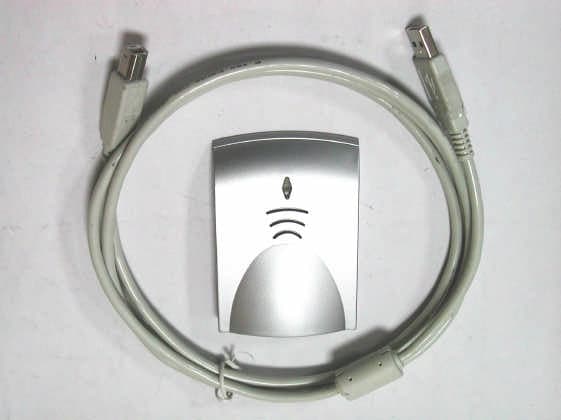
Click to zoom
Application Details
- Equipment Class
- DTS - Digital Transmission System
- Date of Grant
- Apr 29, 2003
- Application Purpose
- Original Equipment
- Date of Application
- Apr 29, 2003
- Equipment Note
- Wireless LAN USB Adapter
- Frequency Range
- 2412.00000000 - 2462.00000000
- Company
- 11 Wave Technology Inc.
- Country
- Taiwan
Documents & Files
Document Text
Text extracted from the exhibit documents filed with the FCC. Open a document above to read the original.
Users Manual
WaveBuddy WLAN PC Card/PCI/USB Adapter User Guide EWP-813WA1 EWU-531WA1 EWC-351WA1 Version 1.0 11Wave Technology Inc. 11Wave Technology Inc. I INFORMATION TO USER Federal Communications Commission Statement This product has been tested and complies with the specifications for a Class B digital device, pursuant to Part 15 of the FCC Rules. These limits are designed to provide reasonable protection against harmful interference in a residential installation. The antenna used for this transmitter must be installed to provide a separation distance of least 20 centimeters from all persons and must operate in conjunction with other antenna or transmitters. This equipment generates, uses, and can radiate radio frequency energy and, if not installed and used according to the instructions, may cause harmful interference to radio communications. However, there is no guarantee that interference will not occur in a particular installation. If this equipment does cause harmful interference to radio or television reception, which is found by turning the equipment off and on, the user is encouraged to try to correct the interference by one or more of the following measures: ◇ Reorient or relocate the receiving antenna ◇ Increase the separation between the equipment or device ◇ Connect the equipment to an outlet other than receiver’s ◇ Consult a dealer or an experienced radio/TV technician for assistance Notice: The Part 15 radio device operates on a non-interference basis with other devices operating at this frequency. Any change or modification not expressly approved by the party responsible could void the user’s authority to operate the device. Regulatory The wireless LAN Card must be installed and used in strict accordance with the manufacturer’s instructions. This device complies with the following radio frequency and safety standards. USA - Federal Communications Commission (FCC) This device complies with Part 15 of FCC Rules. Operation is subject to the following two conditions: 1. This device may not cause harmful interference. 2. This device must accept any interference that may cause undesired operation. Europe - R&TTE Directive This device complies with the specifications listed below: ⌧ETS 300-826 General EMC requirements for Radio equipment. ⌧ETS 300-328 Technical requirements for Radio equipment. ⌧EN60950 Safety requirements for Radio equipment. EU Countries not intended for use The ETSI version of this device is intended for home and office use in Austria, Belgium, Denmark, Finland, France (with Frequency channel restrictions). Germany, Greece, Ireland, Italy, Luxembourg, Netherlands, Portugal, Spain, Sweden and United Kingdom. The ETSI version of this device is also authorized for use in EFTA member states Iceland, Liechtenstein, Norway and Switzerland. 11Wave Technology Inc. II Table of Contents 1. INTRODUCTION ..................................................................................................... 1 1.1 T HE W AV E B UDDY W IRELESS LAN NIC............................................................... 1 1.2 F EATURES ............................................................................................................. 1 1.3 P ACKAGE C ONTENTS ............................................................................................ 1 1.4 S YSTEM R EQUIREMENTS ...................................................................................... 2 2. NETWORK CONFIGURATION AND PLANNING ............................................ 3 2.1 W IRELESS LAN B ASIC ......................................................................................... 3 3. INSTALLATION FOR WINDOWS 9X/ME/2000/XP ........................................... 4 3.1 W HAT Y OU N EED TO K NOW A BOUT W INDOWS 9 X /M E /2000/XP ........................ 4 3.2 W HAT Y OU W ILL N EED ........................................................................................ 4 3.3 I NSTALL PCI A DAPTER D RIVER ............................................................................ 4 3.4 I NSTALL PCI A DAPTER U TILITY ........................................................................... 5 3.5 I NSTALL PC C ARD /USB A DAPTER D RIVER AND U TILITY .................................... 9 3.6 U NINSTALL P ROCEDURE U NDER W INDOWS 9 X /M E ............................................ 13 3.7 U NINSTALL P ROCEDURE U NDER W INDOWS 2000/XP ........................................ 13 4. INSTALLATION FOR WINDOWS NT 4.0 ......................................................... 15 4.1 W HAT Y OU N EED TO K NOW A BOUT W INDOWS NT 4.0 ..................................... 15 4.2 W HAT Y OU W ILL N EED ...................................................................................... 15 4.3 I NSTALL PCI A DAPTER ....................................................................................... 15 4.4 I NSTALL PC C ARD .............................................................................................. 16 4.5 I NSTALL U TILITY ................................................................................................ 17 4.6 U NINSTALL P ROCEDURE U NDER W INDOWS NT 4.0 ........................................... 17 5. WLAN CONFIGURATION & MONITOR UTILITY ........................................ 18 5.1 H OW TO A CCESS THE WLAN C ONFIGURATION & M ONITOR U TILITY ................ 18 5.2 U SING THE WLAN C ONFIGURATION & M ONITOR U TILITY ................................ 18 5.3 C OLLABORATING WITH W INDOWS XP ................................................................ 23 APPENDIX A................................................................................................................... 25 APPENDIX B : GLOSSARY.......................................................................................... 27 11Wave Technology Inc. 1 1. Introduction 1.1 The WaveBuddy Wireless LAN NIC Thank you for purchasing the WaveBuddy Wireless LAN product. The WaveBuddy WLAN Network Interface Card (NIC) …
Text truncated - open the document above for the full version.
Cover Letter(s)
Request for Confidentiality Federal Communications Commission Authorization and Evaluation Division Sub.: Confidentiality Request regarding application for certification of FCC ID: QS4-511A Pursuant to Sections 0.457 and 0.459 of the Commission’s Rules, we hereby request confidential treatment of information accompanying this application as outlined below: l Schematics l Part List The above materials contain trade secrets and proprietary information not customarily released to the public. The public disclosure of these materials may be harmful to the applicant and provide unjustified benefits to its competitors. The applicant understands that pursuant to Section 0.457 of the Rules, disclosure of this application and all accompanying documentation will not be made before the date of the Grant for this application. Sincerely, Godspeed(M.J.) Huang, Manager 11 Wave Technology Inc.
ID Label/Location Info
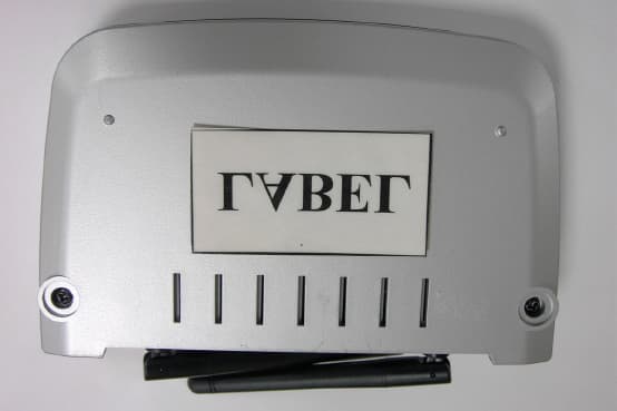
LABEL Format: LABEL Position: Size: 51.50 x 31.00 mm
Operational Description
ATMEL OPERATION DESCRIPTION for USB Adapter Project name : 11WU-511A 1: T/R switch: a: TX or RX multiplexing switch, TX/RX are half duplex. B: Antenna A or B switch. 2: RF5117 : 2.4GHz Power Amplifier RF5117 is a linear, medium-power, high-efficiency amplifier IC designed specifically for battery-powered WLAN applications .The devices manufactured on an advanced Gallium Arsendie Heterojunction Bipolar Transistor(HBT) process, and has been designed for use as the Final RF amplifier in 2.5GHz WLAN and other spread-spectrum transmitters. The device is provider in a 3mmX3mm, 16 pin, leadless chip carrier with a backside ground. The RF5117 is designed to maintain linearity over a wide range of supply voltage and power output. RF5117 requires only a single positive supply of 3.0V nominal(or greater) to operate to full specifications. Power control is provided through two bias control input pins (Vreg1 and Vreg2). External matching on the input and output . Both the input and the output of the device need a series DC-blocking capacitor. Capacitor used as a matching component can also serve as the blocking Cap. Features: --Single 3.3V Power Supply --+30dBm Saturated Output Power --26dB Small Signal Gain 3: RF2948 2.4GHz SPREAD-SPECTRUM TRANSCEIVER RF2948 is a monolithic integrated circuit specifically designed for Direct-sequence spread-spectrum systems operating in a 2.4GHz ISM band. The part include: a direct conversion from IF receiver With variable gain control; quadrature demodulator; I/Q baseband amplifier, and on chip programmable baseband filter. For the transmit side, a QPSK modulator and the upconverter are provided. The design reuses the IF SAW filter for transmit and receive deducing the number of SAW filters required. RF2948 is also designed to be of a 2.4GHz chipset consisting of the RF2494 LNA/Mixer. Features: --45MHz to 500MHz IF Quad Demod --On-chip Variable Baseband Filters --Quadrature Modulator and Upconverter --2.7V to 3.6V Operation --2.4GHz PA Driver 4: RF2494 : HIGH FREQUENCY LNA/MIXER RF2494 is a monolithic integrated UHF receiver front end suitable for 2.4GHz ISM band applications. The IC contains all of the required components to implement the RF functions of the receiver except for the passive filtering and LO generation. It contains an LNA, a second RF amplifier and a doubly balanced mixer. The output of the LNA is made available as an output to permit the insertion of a bandpass filter between the LNA and the RF/Mixer section. The mixer outputs can beselectively disabled to allow for the IF filter to be used in the transmit mode. The cascaded power gain of the LNA/Mixer is 29dB, which after insertion loss in the image filter(`3dB) and IF SAW filter(~1-dB), still gives 16dB of gain prior to the IF Amps. Because of this, the noise figure of the IF Amps should not significantly degrade system noise figure. Features: --Single 2.7V to 3.6V Power Supply. --2400MHz to 2500MHz Operation. --Two Gain setting: 28dB or 12dB. --4.5dB Cascaded NF, high Gain Mode. --20mA DC Current Consumption --Input IP3: -23dBm or –8dBm 5: RF3000 : SPREAD-SPECTRUM BASEBAND MODEM RF3000 is a monolithic CMOS baseband processor. It is suitable for use in 11Mbps IEEE802.11b wireless LNA systems and general purpose ISM band radios, and contains all functions required to convert a spread-spectrum signal to bit stream. PN code lengths up to 64 bits allows increased processing gain. The on-chip equalizer provides protection against multi-path in the data rate modes. All functions are configurable via SPI port. A complete 2.4GHz radio reference design is available from RFMD.RF300 receiver port provides a clear channel assessment(CCA) to the MAC and supports PSK and CCK DSSS mode. Features: --On-chip ADCs and DACs, RSSI, AGC --BPSK/QPSK/CCK --250ns Dealy spread Equalizer --Supports Antenna Diversity --PN Sequences Up To 64Bits Long 6: AT76C503A WIRELESS NETWORK INTERFACE Universal Serial Bus 11-Mbps MEDIA ACCESS CONTROLLER The Atmel AT76C503A is a network card with a rate of 1, 2, 5.5, and 11 Mbps operating in the ISM band using Direct Sequence Spread Spectrum(DSSS) transmission, implementing the IEEE802.11b and 802.11 standard. AT76C503A is a single-chip controller that provides all processing and functionality needed for the MAC protocol of wireless LANs(focusing on, but not limited to the IEEE802.11b standard). It provides a glueless interface conforming to 12-Mbit universal serial bus specification and can control a variety of physical interfaces. AT76C503A chip contains a USB interface, a MAC control unit and a physical attachment interface(PAI). The PAI supports direct-sequence spread spectrum and frequency-hopping spread spectrum(2 Mbps) physical interfaces, providing flexibility to end users. The ARM7TDMI core supports two alternative instruction sets. Powerful 32-bit code can be executed by the processor in ARM operating mode. However, a 16-bit instruction subset is also available in Thumb mode. Thumb mode can be selected to exploit full processor power with limited external memory resources. Note that ARM7TDMI operating mode can be changed at run time with negligible overhead. Features: IEEE 802.11b Direct Sequence high rate compatible --High data rate, 11/5.5/2/1 Mbps --Auto Rate fallback --IPX, NetBEUI, TCP/IP protocols supported. --Wired Equivalent Privacy Algorithm (WEP) (64 bits/128 bits) --802.11 Power save in infrastructure mode --Passive/Active scan. Long/Short preamble --RTS/CTS handshake --Site Survey --Roaming --Dynamic configuration --Beacon and Probe response generation in an IBSS. --Plug-and-Play and easy setup
RF Exposure Info
Training Research Co., Ltd. 255 Nanyang Street, Shijr, Taipei Hsien 221, Taiwan, R.O.C. TEL: 886-2-26935155 FAX: 886-2-26934440 TRCSince1985 ® Measurement of MPE 1. Foreword In adopt with the Human Exposure IEEE C95.1, and according to the FCC 1.1310. The Maximum Permissible Exposure (MPE) is obligated to measure in order to prove the safety of radiation harmfulness to the human body. The Gain of the antenna used is measured in an Anechoic chamber. The maximum total power to the antenna is to be recorded. By adopting the Friis Transmission Formula and the power gain of the antenna, we can find the distance right away from the product, where the limit of the MPE is. 2. Description of EUT Applicant : 11Wave Technology Inc., Applicant Address : 3F No. 6 Lane35 jihu Rd., Neihu, Taipei, Taiwan 114, R.O.C. Classification : Portable Device (i) Under normal use condition, the antenna is at least 20cm away from the user; (ii) Warning statement for keeping 20cm separation distance and the prohibition of operating next to the person has been printed in the user’s manual Model No. : PWC-532, 11WP-511A, 11WP-511AXXXX (X: 0~9, A~Z, a~z, Blank) Granted FCC ID : QS4-511A Frequency Range : 2.412 GHz ~ 2.462GHz Support Channel : 11 Channel Modulation Skill : BPSK, QPSK, CCK Power Type : By the USB Interface of Computer Training Research Co., Ltd. 255 Nanyang Street, Shijr, Taipei Hsien 221, Taiwan, R.O.C. TEL: 886-2-26935155 FAX: 886-2-26934440 TRCSince1985 ® 3. Limits for Maximum Permissible Exposure (MPE) Frequency Range (MHz) Electric Field Strength (V/m) Magnetic Filed Strength (H) (A/m) Power Density (S) (mW/cm2) Averaging Time |E| 2 , |H| 2 or S (minutes) (A) Limits for Occupational/Controlled Exposure 0.3-3.0 614 1.63 100 6 3.0-30 1842/f 4.89/f 900/f 2 6 30-300 61.4 0.163 1.0 6 300-1500 -- -- f/300 6 1500-100,000 -- -- 5 6 (B) Limits for General Population/Uncontrolled Exposure 0.3-1.34 614 1.63 100 30 1.34-30 824/f 2.19/f 180/f 2 30 30-300 27.5 0.073 0.2 30 300-1500 -- -- f/1500 30 1500-100,000 -- -- 1.0 30 [The EUT is tested in transmit and receive modes and in the first, middle and the last channel separately. The following shows only our observation have the greatest emissions.] According to OET BULLETIN 56 Fourth Edition/August 1999, Equation for Predicting RF Fields: Friis Transmission Formula: 2 22 /011.0 )20(4 229 4 cmmW R PG S= × == ππ Estimated safe separation: cm PG R148.2 4 229 4 = × == ππ Remarks: "The safe estimated separation that the user must maintain from the antenna is at least 1.890 cm." Where: S = power density (in appropriate units, e.g. mW/cm2) P = power input to the antenna (in appropriate units, e.g., mW) G = power gain of the antenna in the direction of interest relative to an isotropic radiator R = distance to the center of radiation of the antenna (appropriate units, e.g., cm) The Numeric gain G of antenna with a gain specified in dB is determined by: G = Log -1 (dB antenna gain/10) G = Log -1 (2.0 / 10) = 1.584
Test Report
Test Report ----------------------------------------------------------------------------- 1/38 Report No.: W2615003, FCC Part 15 Training Research Co., Ltd., TEL: 886-2-26935155, Fax: 886-2-26934440 MEASUREMENT REPORT of 2.4G USB Wireless LAN Applicant : 11Wave Technology, Inc. Model No. : PWU-532, 11WU511A, 11WU511AXXXX (X: 0~9, A~Z, a~z, Blank) EUT : Wireless LAN USB Adapter FCC ID : QS4-511A Report No. : W2615003 Tested by : Training Research Co., Ltd. TEL : 886-2-26935155 FAX : 886-2-26934440 No. 255, Nanyang Street, Shijr, Taipei Hsien 221, Taiwan, R.O.C. Test Report ----------------------------------------------------------------------------- 2/38 Report No.: W2615003, FCC Part 15 Training Research Co., Ltd., TEL: 886-2-26935155, Fax: 886-2-26934440 CERTIFICATION We here by verify that: The test data, data evaluation, test procedures and equipment configurations shown in this report were made mainly in accordance with the procedures given in ANSI C63.4 (1992) as a reference. All test were conducted by Training Research Co., Ltd., 255 Nanyang Street, Shijr, Taipei Hsien 221, Taiwan, R.O.C. Also, we attest to the accuracy of each. We further submit that the energy emitted by the sample EUT tested as described in the report is in compliance with the technical requirements set forth in the FCC Rules Part 15 Subpart C Section 15.247. Applicant : 11Wave Technology, INC. Applicant address : 3F No. 6 Lane 35, jihu Rd., Neihu, Taipei, Taiwan R.O.C. EUT : Wireless LAN USB Adapter Model No. : PWU-532, 11WU511A, 11WU511AXXXX (X:0~9, A~Z, a~z, Blank) FCC ID : QS4-511A Report No. : W2615003 Test Date : November 22, 2002 Prepared by: Approved by: Jack Tsai Frank Tsai Tested by : Training Research Co., Ltd. TEL: 886-2-26935155 FAX: 886-2-26934440 255 Nanyang Street, Shijr, Taipei Hsien 221, Taiwan, R.O.C. Test Report ----------------------------------------------------------------------------- 3/38 Report No.: W2615003, FCC Part 15 Training Research Co., Ltd., TEL: 886-2-26935155, Fax: 886-2-26934440 Federal Communications Commission Declaration of Conformity (DoC) For the Following Equipment: Product name : Wireless LAN USB Adapter Model name : PWC-532, 11WP-511A, 11WP-511AXXXX (X: 0~9, A~Z, a~z, Blank) Trade name : 11Wave Technology Inc. Is herewith confirmed and found to comply with the requirements of CFR 47 part15 Subpart B - Unintentional Radiators regulation. The results of electromagnetic mission evaluation are shown in the report number : W2615003 This device complies with Part 15 of the FCC Rules. Operation is subject to the following two conditions: (1) This device may not cause harmful interference, and (2) This device must accept any interference received, including interference that may cause undesired operation Manufacturer USA local representative Company name: 11 Wave Technology Inc. To be determined Computer address: No. 6 Lane 35, jihu Rd., Neihu, Taipei, Taiwan R.O.C. ZIP / Postal code 114 Contact person: M.J. Huang Title: R & D Manager Internet e-mail address: [email protected] Tel / Fax: 886-2-87515588 / 886-2-26598782 Test Report ----------------------------------------------------------------------------- 4/38 Report No.: W2615003, FCC Part 15 Training Research Co., Ltd., TEL: 886-2-26935155, Fax: 886-2-26934440 Tables of Contents I. GENERAL ........................................................................................................................ 6 1.1 Introduction ................................................................................................................. 6 1.2 Description of EUT ..................................................................................................... 6 1.3 Description of Support Equipment ............................................................................. 7 1.4 Test method ................................................................................................................. 9 1.5 Configuration of System Under Test .......................................................................... 9 1.6 Verify the Frequency and Channel ............................................................................. 11 1.7 Test Procedure ........................................................................................................... 12 1.8 Location of the Test Site ............................................................................................ 12 1.9 General Test Condition .............................................................................................. 12 II. Section 15.101(a) : Equipment Authorization of Unintentional Radiators................. 13 III. Section 15.203 : Antenna Requirement........................................................................... 14 IV. Section 15.207 : Power Line Conducted Emissions for AC Powered Units ............... 15 4.1 Test Condition & Setup ............................................................................................. 15 4.2 List of Test Instruments ............................................................................................. 15 4.3 Test Result of Conducted Emissions ......................................................................... 16 Channel 01 ................................................................................................................. 16 Channel 06 ................................................................................................................. 17 Channel 11 ................................................................................................................. 18 V. Section 15.247(a) : Technical Description of the EUT................................................... 19 VI. Section 15.247(a)(2) : Bandwidth for Direct Sequence System ................................... 20 6.1 Test Condition & Setup ............................................................................................. 20 6.2 Test Instruments Configuration ...…
Text truncated - open the document above for the full version.
Test Setup Photos
Test Setup Photos ------------------------------------------------------------------------ 1/3 FCC ID:QS4-511A Training Research Co., Ltd., TEL: 886-2-26935155, Fax: 886-2-26934440 Conducted Test Setup Placement: Front View of the Test Configuration Side View of the Test Configuration Test Setup Photos ------------------------------------------------------------------------ 2/3 FCC ID:QS4-511A Training Research Co., Ltd., TEL: 886-2-26935155, Fax: 886-2-26934440 Radiated Test Setup Placement: (Unintentional) Front View of the Test Configuration of Unintentional Rear View of the Test Configuration of Unintentional Test Setup Photos ------------------------------------------------------------------------ 3/3 FCC ID:QS4-511A Training Research Co., Ltd., TEL: 886-2-26935155, Fax: 886-2-26934440 Radiated Test Setup Placement: (Intentional) Front View of the Test Configuration of Intentional Rear View of the Test Configuration of Intentional
Contact Information
Applicant
Godspeed Huang(R&D Manager)
Test Firm
Training Research Co., Ltd.Jack Tsai
Technical Specifications
| # | Rule Parts | Frequency Range | Power Output |
|---|---|---|---|
| 1 | 15C | 2.41 GHz - 2.46 GHz | 29.37 mW |
Other Applications from 11 Wave Technology Inc.
QS4-321A
Jun 02, 2003Access Point
Equipment Class
DTS - Digital Transmission System
QS4611AL
Apr 22, 200311 Mbps Wireless PC Card
Equipment Class
DTS - Digital Transmission System