QSE13EAQSEVTag
VTrump Tech (Shanghai) Co.,Ltd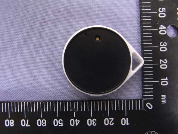
Click to zoom
Application Details
- Equipment Class
- DTS - Digital Transmission System
- Date of Grant
- Nov 14, 2012
- Application Purpose
- Original Equipment
- Date of Application
- Nov 14, 2012
- Equipment Note
- VTag
- Frequency Range
- 2402.00000000 - 2480.00000000
- Country
- China
Documents & Files
Document Text
Text extracted from the exhibit documents filed with the FCC. Open a document above to read the original.
Users Manual
User Manual VTag Anti‐Loss Device An Advanced Object Finder VTrump Te c h (Shanghai) Co., Ltd FCC Notices 1. The manufacturer is not responsible for any radio or TV interference caused by unauthorized modifications to this equipment. Such modifications could void the user’s authority to operate the equipment. 2. This device complies with Part 15 of the FCC Rules. (1) This device may not cause harmful interference, and (2) this device must accept any interference received, including interference that may cause undesired operation. NOTE: This equipment has been tested and found to comply with the limits for a Class B digital device, pursuant to part 15 of the FCC Rules. These limits are designed to provide reasonable protection against harmful interference in a residential installation. This equipment generates uses and can radiate radio frequency energy and, if not installed and used in accordance with the instructions, may cause harmful interference to radio communications. However, there is no guarantee that interference will not occur in a particular installation. If this equipment does cause harmful interference to radio or television reception, which can be determined by turning the equipment off and on, the user is encouraged to try to correct the interference by one or more of the following measures: Reorient or relocate the receiving antenna. Increase the separation between the equipment and receiver. Connect the equipment into an outlet on a circuit different from that to which the receiver is connected. Consult the dealer or an experienced radio/TV technician for help. Battery 1. Take out VTag and the complimentary CR2032 battery from the package. 2. Install Battery a) Rotate 90 degrees clockwise, and detach the battery cover from VTag. b) Insert the CR2032 into battery slot in the arrow’s direction, press it until a slight click c) Recover the battery cover by the rotation by half of a turn anticlockwise. 3. Replace Battery Open the battery cover, Push CR2032 in the arrow’s direction, and take out CR2032. SETUP Step 1 Please Search and Download Blue Smart at iTunes App Store http://itunes.apple.com/us/app/blue-smart/id536898116?ls=1&mt=8 Step 2 Touch "Settings" then "General" on your iPhone's screen. Touch "Bluetooth" then touch "Turn Bluetooth On." And open Blue Smart app in iPhone 4s, iPhone 5 or new iPad. Step 3 Press Connect(●) button 3 seconds to pair the VTag device with iPhone or iPad. The Blue Smart app will discover VTag, please tap “Pair” to permit the VTag connection. Functions Status Caused By VTag Beeper VTag LED Pairing Long press Connect button in disconnected status, BlueSmart in searching device 2 beeps to entering pairing Continuous fast green-light flashing with 0.5s interval, and last 60s. Disconnected out of range or control to disconnect Beeps for 5s Slow continuous green-light flashing with 5s interval Connected Paired and connected N/Y A fast green flashing for 2s to enter Connected Status, then no light Findme Alert "Findme" in BlueSmart APP an immediate alert N/Y Mute Alert "Mute" in BlueSmart APP stop alert N/Y Short Alert in iPhone/iPad Short Push Connect and Function button together N/Y N/Y High Alert in iPhone/iPad Long Push (>3S) Connect and Function button together N/Y N/Y
RF Exposure Info
MPE TEST REPORT FCC Per 47 CFR 2.1093(d) Report Reference No. ..................... : FCC ID. ............................................ : TRE1210001402 R/C:59226 QSE13EAQSE Compiled by ( position+printed name+signature) .. : File administrators Tim Zhang Supervised by ( position+printed name+signature) .. : Test Engineer Eric Zhang Approved by ( position+printed name+signature) .. : Manager Wenliang Li Date of issue ..................................... : Oct 30, 2012 Testing Laboratory Name .............. : Shenzhen Huatongwei International Inspection Co., Ltd Address ............................................. : Keji Nan No.12 Road, Hi-tech Park, Shenzhen, China Applicant’s name ............................ : VTrump Tech (Shanghai) Co., Ltd Address ............................................. : Rm 2206, 66-1 Huayuan Road, Shanghai, China Test specification: Standard ........................................... : FCC Per 47 CFR 2.1093(d) TRF Originator .................................. : Shenzhen Huatongwei International Inspection CO., Ltd Master TRF ....................................... : Dated 2006-06 Shenzhen Huatongwei International Inspection Co., Ltd. All rights reserved. This publication may be reproduced in whole or in part for non-commercial purposes as long as the Shenzhen Huatongwei International Inspection Co., Ltd is acknowledged as copyright owner and source of the material. Shenzhen Huatongwei International Inspection Co., Ltd takes no responsibility for and will not assume liability for damages resulting from the reader's interpretation of the reproduced material due to its placement and context. Test item description .................... : VTag Trade Mark ....................................... : / Model/Type reference ....................... : M20 Listed Models .................................. : / Operation Frequency ........................ : From 2400MHz to 2483.5MHz Result ................................................ : Positive Report No.: TRE1210001402 Page 2 of 6 Issued:2012-10-30 MPE T E S T R E P O R T Test Report No. : TRE1210001402 Oct 30, 2012 ______________________________________________________________________________________________ Date of issue Equipment under Test : VTag Model /Type : M20 Listed Models : / Applicant : VTrump Tech (Shanghai) Co., Ltd Address : Rm 2206, 66-1 Huayuan Road, Shanghai, China Manufacturer VTrump Tech (Shanghai) Co., Ltd Address : Rm 2206, 66-1 Huayuan Road, Shanghai, China The test report merely corresponds to the test sample. It is not permitted to copy extracts of these test result without the written permission of the test laboratory. Report No.: TRE1210001402 Page 3 of 6 Issued:2012-10-30 Contents 1. SUMMARY ............................................................................. 4 1.1. EUT configuration 4 1.2. NOTE 4 2. TEST ENVIRONMENT ............................................................... 5 2.1. Address of the test laboratory 5 2.2. Environmental conditions 5 2.3. Statement of the measurement uncertainty 5 3. METHOD OF MEASUREMENT .................................................... 5 3.1. Applicable Standard 5 3.2. Limit 6 3.3. MPE Calculation Method 6 4. CONCLUSION ........................................................................ 6 Report No.: TRE1210001402 Page 4 of 6 Issued:2012-10-30 1. SUMMARY 1.1. EUT configuration The following peripheral devices and interface cables were connected during the measurement: ● - supplied by the manufacturer ○ - supplied by the lab ○ Power Cable Length (m) : / Shield : / Detachable : / ○ Multimeter Manufacturer : / Model No. : / 1.2. NOTE 1. The EUT is a VTag,The functions of the EUT listed as below: Test Standards Reference Report Bluetooth 4.0 FCC Part 15 Subpart C (Section15.247) TRE1210001401 MPE REPORT FCC Per 47 CFR 2.1093(d) TRE1210001402 2. The frequency bands used in this EUT are listed as follows: Frequency Band(MHz) 2400-2483.5 5150-5350 5470-5725 5725-5850 Bluetooth √ - - - 3. The EUT provides one completed transmitter and receiver. Modulation Mode TX Function Bluetooth 1TX Report No.: TRE1210001402 Page 5 of 6 Issued:2012-10-30 2. TEST ENVIRONMENT 2.1. Address of the test laboratory Shenzhen Huatongwei International Inspection Co., Ltd Keji Nan No.12 Road, Hi-tech Park, Shenzhen, China Phone: 86-755-26715686 Fax: 86-755-26748089 The sites are constructed in conformance with the requirements of ANSI C63.7, ANSI C63.4 (2009) and CISPR Publication 22. 2.2. Environmental conditions During the measurement the environmental conditions were within the listed ranges: Temperature: 15-35 ° C Humidity: 30-60 % Atmospheric pressure: 950-1050mbar 2.3. Statement of the measurement uncertainty The data and results referenced in this document are true and accurate. The reader is cautioned that there may be errors within the calibration limits of the equipment and facilities. The measurement uncertainty was calculated for all measurements listed in this test report acc. to TR-100028-01” Electromagnetic compatibility and Radio spectrum Matters (ERM);Uncertainties in the measurement of mobile radio equipment characteristics; Part 1” and TR-100028-02 “Electromagnetic compatibility and Radio spectrum Matters (ERM);Uncertainties in the measurement of mobile radio equipment characteristics; Part 2 “ and is documented in the Shenzhen Huatongwei International Inspection Co., Ltd quality system acc. to DIN EN ISO/IEC 17025. Furthermore, component and process variability of devices similar to that tested may result in additional deviation. The manufacturer has the sole responsibility of continued compliance of the device. Hereafter the best measurement capability for Shenzhen Huatongwei laboratory is reported: Test Items Measurement Uncertainty Notes Transmitter power conducted 0.57 dB (1) (1) This uncertainty represents an expanded uncertainty expressed at approximately the 95% confidence level using a coverage factor of k=1.96. 3. Method of measurement 3.1. …
Text truncated - open the document above for the full version.
Test Report
FCC PART 15 SUBPART C TEST REPORT FCC PART 15.247 Report Reference No. ..................... : FCC ID. .............................................: TRE1210001401 R/C:59226 QSE13EAQSE Compiled by ( position+printed name+signature) .. : File administrators Tim Zhang Supervised by ( position+printed name+signature) .. : Test Engineer Eric Zhang Approved by ( position+printed name+signature) .. : Manager Wenliang Li Date of issue ..................................... : Oct 29, 2012 Testing Laboratory Name .............. : Shenzhen Huatongwei International Inspection Co., Ltd Address ............................................ : Keji Nan No.12 Road, Hi-tech Park, Shenzhen, China Applicant’s name ............................ : VTrump Tech (Shanghai) Co., Ltd Address ............................................ : Rm 2206, 66-1 Huayuan Road, Shanghai, China Test specification: Standard ........................................... : FCC Part 15.247: Operation within the bands 902-928 MHz, 2400-2483.5 MHz and 5725-5850 MHz TRF Originator .................................. : Shenzhen Huatongwei International Inspection CO., Ltd Master TRF ....................................... : Dated 2006-06 Shenzhen Huatongwei International Inspection Co., Ltd. All rights reserved. This publication may be reproduced in whole or in part for non-commercial purposes as long as the Shenzhen Huatongwei International Inspection Co., Ltd is acknowledged as copyright owner and source of the material. Shenzhen Huatongwei International Inspection Co., Ltd takes no responsibility for and will not assume liability for damages resulting from the reader's interpretation of the reproduced material due to its placement and context. Test item description ..................... : VTag Trade Mark ....................................... : / Model/Type reference ....................... : M20 Listed Models .................................. : / Operation Frequency ........................ : From 2400MHz to 2483.5MHz Result................................................ : Positive Report No.: TRE1210001401 Page 2 of 35 Issued:2012-10-29 T E S T R E P O R T Test Report No. : TRE1210001401 Oct 29, 2012 ______________________________________________________________________________________________ Date of issue Equipment under Test : VTag Model /Type : M20 Listed Models : / Applicant : VTrump Tech (Shanghai) Co., Ltd Address : Rm 2206, 66-1 Huayuan Road, Shanghai, China Manufacturer VTrump Tech (Shanghai) Co., Ltd Address : Rm 2206, 66-1 Huayuan Road, Shanghai, China Test Result according to the standards on page 4: Positive The test report merely corresponds to the test sample. It is not permitted to copy extracts of these test result without the written permission of the test laboratory. Report No.: TRE1210001401 Page 3 of 35 Issued:2012-10-29 Contents 1. TEST STANDARDS .................................................................. 4 2. SUMMARY ............................................................................. 5 2.1. General Remarks 5 2.2. Equipment Under Test 5 2.3. Short description of the Equipment under Test (EUT) 5 2.4. EUT operation mode 5 2.5. EUT configuration 5 2.6. Related Submittal(s) / Grant (s) 6 2.7. Modifications 6 2.8. NOTE 6 3. TEST ENVIRONMENT ............................................................... 7 3.1. Address of the test laboratory 7 3.2. Test Facility 7 3.3. Environmental conditions 8 3.4. Configuration of Tested System 8 3.5. Test Description 8 3.6. Statement of the measurement uncertainty 9 3.7. Equipments Used during the Test 9 4. TEST CONDITIONS AND RESULTS ............................................ 11 4.1. AC Power Conducted Emission 11 4.2. Radiated Emission 12 4.3. Maximum Peak Output Power 18 4.4. Power Spectral Density 20 4.5. Band Edge Compliance of RF Emission 23 4.6. Spurious RF Conducted Emission 25 4.7. 6dB Bandwidth 29 4.8. Antenna Requirement 31 5. TEST SETUP PHOTOS OF THE EUT .......................................... 32 6. EXTERNAL AND INTERNAL PHOTOS OF THE EUT ....................... 33 Report No.: TRE1210001401 Page 4 of 35 Issued:2012-10-29 1. TEST STANDARDS The tests were performed according to following standards: FCC Rules Part 15.247: Frequency Hopping, Direct Spread Spectrum and Hybrid Systems that are in operation within the bands of 902-928 MHz, 2400-2483.5 MHz, and 5725-5850 MHz. ANSI C63.10 : American National Standard for Testing Unlicensed Wireless Devices KDB558074: DTS Meas Guidance v01 of Measurement Procedure Report No.: TRE1210001401 Page 5 of 35 Issued:2012-10-29 2. SUMMARY 2.1. General Remarks Date of receipt of test sample : Oct 15, 2012 Testing commenced on : Oct 15, 2012 Testing concluded on : Oct 29, 2012 2.2. Equipment Under Test Power supply system utilised Power supply voltage : ○ 120V / 60 Hz ○ 115V / 60Hz ○ 12 V DC ○ 24 V DC ○ Other (specified in blank below) DC 3.0V 2.3. Short description of the Equipment under Test (EUT) 2.4GHz (VTag (M20)) For more details, refer to the user’s manual of the EUT. Serial number: Prototype 2.4. EUT operation mode The EUT has been tested under typical operating condition.The Applicant provides Bluetooth tools software to control the EUT for staying in continous transmitting and receiving mode for testing. There are 40 channels of EUT, and the test carried out at the lowest channel, middle channel and highest channel. Frequency Range: 2402-2480MHz Channel number: 40 channels Modulation type: Bluetooth 4.0-LE: GFSK Antenna Gain: 1.0dBi Antenna type: Ceramic antenna 2.5. EUT configuration The following peripheral devices and interface cables were connected during the measurement: ● - supplied by the manufacturer ○ - supplied by the lab Report No.: TRE1210001401 Page 6 of 35 Issued:2012-10-29 ○ Power Cable Length (m) : / Shield : / Detachable : / ○ Multimeter Manufacturer : / Model No. : / 2.6. Related Submittal(s) / Grant (s) This submittal(s) (test report) is intended for FCC ID: QSE13EAQSE filing to comply w…
Text truncated - open the document above for the full version.
Test Setup Photos
EUT
Contact Information
Applicant
SHENGXI XIE
Test Firm
Shenzhen Huatongwei International Insp. Co., LtdMoffy Yu
Technical Specifications
| # | Rule Parts | Frequency Range | Power Output |
|---|---|---|---|
| 1 | 15C | 2.40 GHz - 2.48 GHz | 2.50 mW |
Other Applications from VTrump Tech (Shanghai) Co.,Ltd
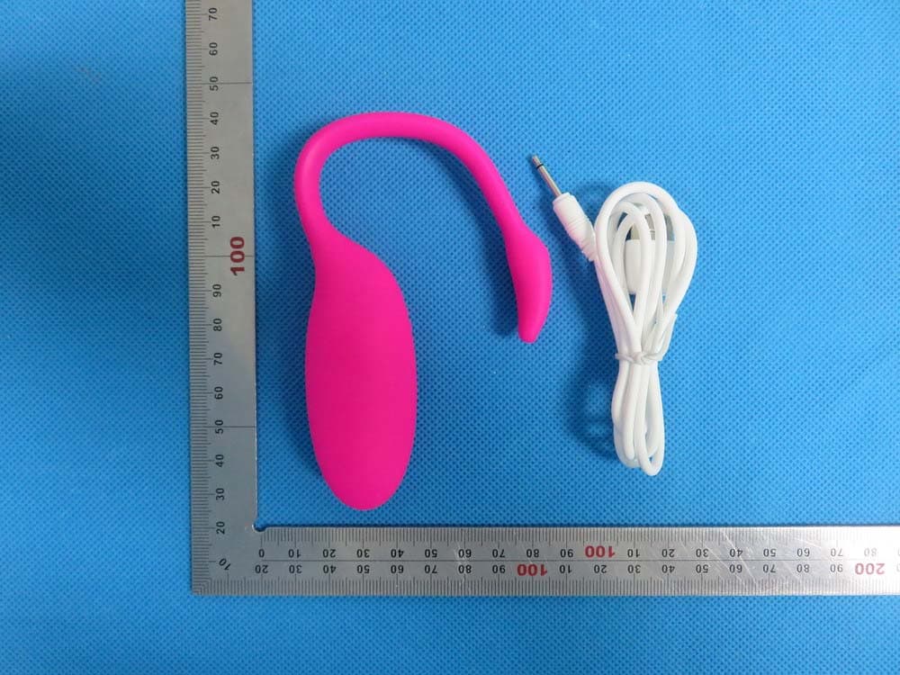
QSESMV5
Aug 31, 2015Magic Motion Flamingo
Equipment Class
DXX - Part 15 Low Power Communication Device Transmitter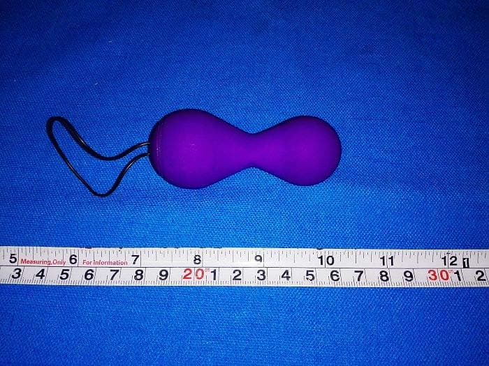
QSESMV02
Oct 19, 2014Magic Kegel / Juve
Equipment Class
DTS - Digital Transmission System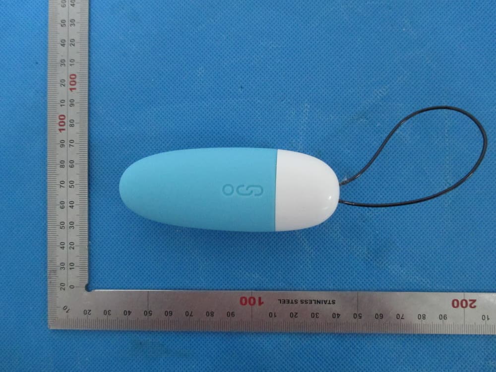
QSESMV01
Jan 22, 2014Smart Mini Vibe
Equipment Class
DTS - Digital Transmission System