QSHBCM2604Bluetooth Barcode Scanner BCM 2604
XIRING SA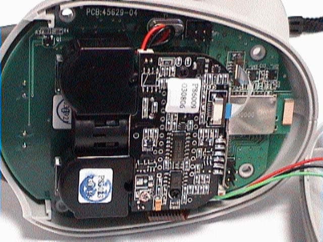
Click to zoom
Application Details
- Equipment Class
- DSS - Part 15 Spread Spectrum Transmitter
- Date of Grant
- Jul 29, 2004
- Application Purpose
- Original Equipment
- Date of Application
- Jul 29, 2004
- Equipment Note
- Bluetooth Barcode Scanner BCM 2604
- Frequency Range
- 2402.00000000 - 2480.00000000
- Company
- XIRING SA
- Country
- France
Documents & Files
Document Text
Text extracted from the exhibit documents filed with the FCC. Open a document above to read the original.
Users Manual
BCM2604 User Guide © Baracoda 2003 Page 1/10 BCM2604 User guide This document is to be used with Baracoda Barcode Scanners: BCM2604-L BCM2604-F 1 Package contents Check that you have the following items. Contact your reseller if any item is missing. 1 barcode scanner (BCM2604) 1 Cradle 1 CD Rom with documentation and software 1 AC charger 2 Batteries BCM2604 User Guide © Baracoda 2003 Page 2/10 Table of content 1 Package contents........................................................................................................................ 1 2 Interface .................................................................................................................................... 3 3 Installing / replacing batteries...................................................................................................... 3 4 Quick Start up guide ................................................................................................................... 4 5 Status Display Summary .............................................................................................................. 5 6 Configuring your scanner............................................................................................................. 6 6.1 Usage modes ........................................................................................................................ 6 6.1.1 Real Time Mode (default setting) ..................................................................................... 6 6.1.2 Master mode .................................................................................................................. 6 6.2 Reading mode ....................................................................................................................... 6 6.2.1 Trigger mode (default setting) ......................................................................................... 6 6.3 Symbology ............................................................................................................................ 6 6.4 Data format........................................................................................................................... 6 6.4.1 Acknowledgment: ........................................................................................................... 6 6.4.2 Prefix / suffix .................................................................................................................. 6 6.4.3 Baracoda Header ............................................................................................................ 7 6.4.4 Barcode Identifier ........................................................................................................... 7 6.5 Beeps and LEDs..................................................................................................................... 7 7 Other functions........................................................................................................................... 8 7.1 Power management...............................................................................................................8 7.2 Sniff period ........................................................................................................................... 8 7.3 Low battery........................................................................................................................... 8 7.4 Security ................................................................................................................................ 8 8 Technical specifications ............................................................................................................... 9 9 Safety / Regulatory. .................................................................................................................. 10 BCM2604 User Guide © Baracoda 2003 Page 3/10 2 Interface The BCM2604 is easy to use. Simply press the trigger to scan a barcode. The colour of the LED indicates the status of the device. A beep indicates when the scanner connects to the remote device and when a barcode is scanned successfully. Acknowledgement of a completed scan is configurable by the user. Barcodes are transmitted in real time to the remote host devices/terminals using Bluetooth wireless technology. You can download software updates as well as additional documentation from http://www.baracoda.com/download after registration. Scanner features: 3 Installing / replacing batteries Only use Baracoda approved rechargeable batteries. The use of any other batteries may damage the scanner and void the warranty. Please remove the batteries when you are storing the scanner for more than 30 days. 1. To insert batteries into the BCM2604, push the lock button away from the battery cover, 2. Slide the battery lid downwards. 3. Insert the two (2) AA batteries as indicated inside the battery compartment. 4. Slide the cover up and lock. Notice : Fully charge batteries before first use. Scan area Trigger Batteries inside Bi Color LED Charging cradle Battery cover lock Side view Bottom view Top view Front view BCM2604 User Guide © Baracoda 2003 Page 4/10 4 Quick Start up guide Find below how to quickly verify that your scanner is working correctly, using the BaracodaManager: 1- Make sure that your host device (PC or PDA) is bluetooth enabled. If not, please contact your reseller. 2- Install the BaracodaManager. (update can be downloaded from http://www.baracoda.com/download . ) Make sure that your Bluetooth software is compatible with BaracodaManager. For instructions, see the BaracodaManager user guide. If your Bluetooth software is not compatible, you can test your scanner with Hyper terminal. Refer to Communication Protocol documentation. (Download on http://www.baracoda.com/download.) 3- Insert the batteries in the scanner. 4- Configure the BaracodaManager to connect to the scanner. a. Start the BaracodaManager by selecting Star…
Text truncated - open the document above for the full version.
Cover Letter(s)
Commercial Power of Attorney BARACODA Wireless Technology 36, Rue de Turin 75008 PARIS FRANCE Commercial Power of Attorney for the type approval / registration of the BCM2604 Series in several countries The company 7 layers, D-40880 Ratingen, has been contracted by BARACODA to obtain „Radio Type Approvals“ for the following electronic components, manufactured and/or released by BARACODA : BCM2604 Series Unless future correspondence from BARACODA directs otherwise, please extend your full cooperation to 7 layers regarding matters to the above mentioned products for the period beginning 01.12.03 through 13.04.04. We certify that we are not subject to denial of federal benefits, that includes FCC benefits, pursuant to Section 5301 of the Anti-Drug Abuse ACT of 1988, U.S.C.862. Further, no party, as defined in 47 CFR 1.2002 (b), to the application is subject to denial of federal benefits, that includes FCC benefits. Olivier GIROUD CTO Marly le Roi, July 29, 2004
Cover Letter(s)
36, rue de Turin 75008 PARIS FRANCE Attn: Reviewing Engineer Federal Communications Commission 7435 Oakland Mills Road Columbia, MD 21046 Req : CONFIDENTIALITY REQUEST FOR : ‘BCM2604’s series, Barcode scanner with Bluetooth support, FCC-ID: QSHBCM2604 To Whom It May Concern: This letter serves as an official request for confidentiality under the FCC Rule Section 0.459. We have requested that the schematic diagrams, Parts list and Block diagrams required to be submitted with this application be withheld from public review. The reason for this request is that these documents are company proprietary information that should never get into the possession of competitors, which would be harmful for our business. Do not hesitate to contact me if you have any additional questions. Thank you very much. Olivier GIROUD - CTO July 29th, 2004 Marly le roi, France
External Photos
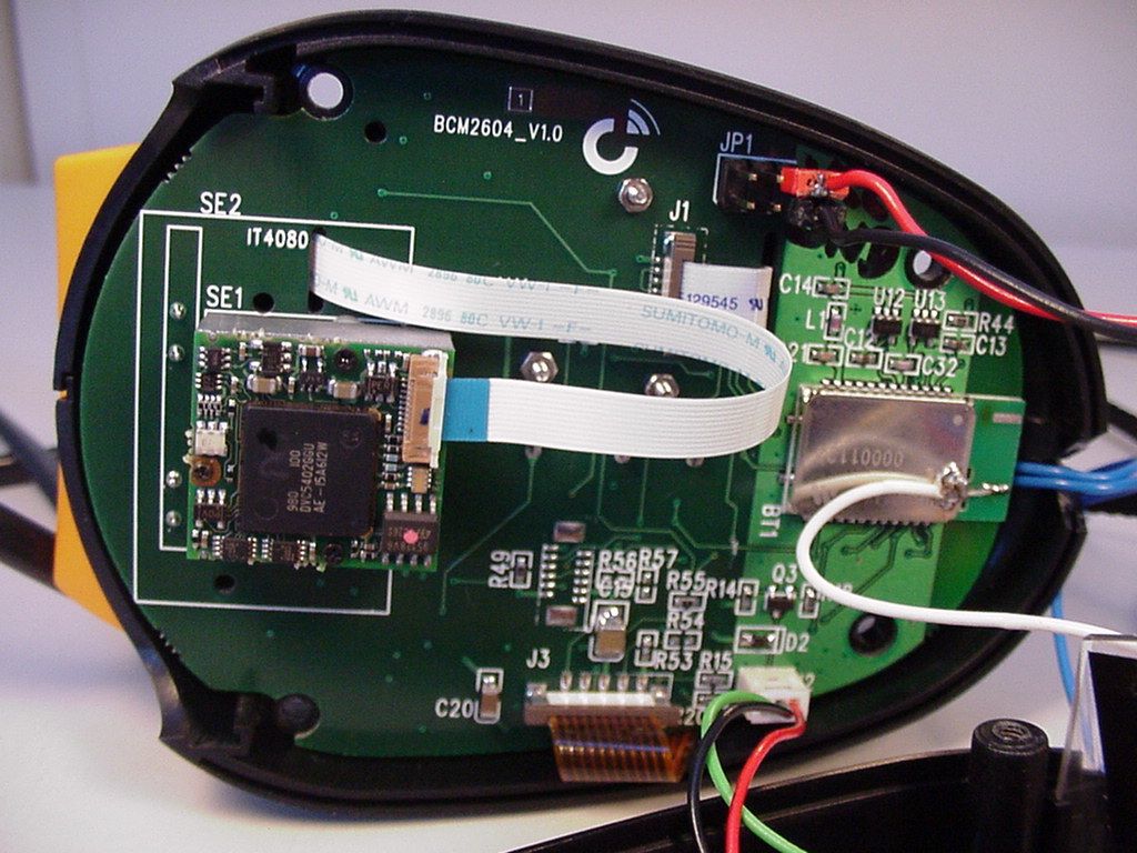
2604 series – Pictures TF Confidential October 2003 2604-series_pictures_031030 1 Housing 2604 series – Pictures TF Confidential October 2003 2604-series_pictures_031030 2 2604 series – Pictures TF Confidential October 2003 2604-series_pictures_031030 3 2604 series – Pictures TF Confidential October 2003 2604-series_pictures_031030 4 INTERNAL POWER PCB 2604 series – Pictures TF Confidential October 2003 2604-series_pictures_031030 5 MAIN BOARD Board without scan engine 2604 series – Pictures TF Confidential October 2003 2604-series_pictures_031030 6 Board with CCD scan engine (BC2604) Board with CCD scan engine (BC2604) 2604 series – Pictures TF Confidential October 2003 2604-series_pictures_031030 7 Board with Laser scan engine (BL2604) Board with Laser scan engine (BL2604)
ID Label/Location Info
BCM2604 series – Label Drawing LW Confidential July 2004 BCM2604-Label-drawing_040721 1 General The label with legal indications is on the top of the trigger : Description of this label : Product Name FCC ID QSHBCM2604 Serial Number Text 2 See below Text 1 See below FCC ID LABELS Label BCM BCM2604 series – Label Drawing LW Confidential July 2004 BCM2604-Label-drawing_040721 2 Details of texts 1 & 2 Text 1 (see previous picture) This device complies with part 15 of the FCC Rules. Operation is subject to the following two conditions : Text 2 (see previous picture) (1) This device may not cause harmful interference (2) This device must accept any interference received including interference that may cause undesired operation.
Internal Photos
2604 series – Pictures TF Confidential October 2003 2604-series_pictures_031030 1 Housing 2604 series – Pictures TF Confidential October 2003 2604-series_pictures_031030 2 2604 series – Pictures TF Confidential October 2003 2604-series_pictures_031030 3 2604 series – Pictures TF Confidential October 2003 2604-series_pictures_031030 4 INTERNAL POWER PCB 2604 series – Pictures TF Confidential October 2003 2604-series_pictures_031030 5 MAIN BOARD Board without scan engine 2604 series – Pictures TF Confidential October 2003 2604-series_pictures_031030 6 Board with CCD scan engine (BC2604) Board with CCD scan engine (BC2604) 2604 series – Pictures TF Confidential October 2003 2604-series_pictures_031030 7 Board with Laser scan engine (BL2604) Board with Laser scan engine (BL2604)
Operational Description
TECHNICAL DESCRIPTION Appliciant Company name: BARACODA Wireless Technology Street: 36, rue de Turin P.O.Box: Postal code/City: 75008 Paris Contact person: Thierry Fortune Telephone: +33 (0) 1 30 08 89 06 Telefax: +33 (0) 1 30 08 89 00 e-mail: [email protected] Manufacturer Company name: BARACODA Wireless Technology Street: 36, rue de Turin P.O.Box: Postal code/City: 75008 Paris, France Contact person: Thierry Fortune Telephone: +33 (0) 1 30 08 89 06 Telefax: +33 (0) 1 30 08 89 00 e-mail: [email protected] 3. Information on the radio equipment Manufacturer: BARACODA Wireless Technology Type designation: BCM 2604 Series Use of the equipment: wireless Bluetooth barcode scanner Equipment category: short range device Frequency / Frequency range: 2400 - 2483.5 MHz Maximum transmitter output power: 10,81 dBm Number of channels and channel separation: 78, 1 MHz Modulation: FHSS Information on antenna: internal Duty cycle: maximum transmission: 92% Power supply: battery Applicable standards: EN 300328-2 ITU Class: 78MOF1D
Operational Description
TECHNICAL DESCRIPTION Appliciant Company name: BARACODA Wireless Technology Street: 36, rue de Turin P.O.Box: Postal code/City: 75008 Paris Contact person: Thierry Fortune Telephone: +33 (0) 1 30 08 89 06 Telefax: +33 (0) 1 30 08 89 00 e-mail: [email protected] Manufacturer Company name: BARACODA Wireless Technology Street: 36, rue de Turin P.O.Box: Postal code/City: 75008 Paris, France Contact person: Thierry Fortune Telephone: +33 (0) 1 30 08 89 06 Telefax: +33 (0) 1 30 08 89 00 e-mail: [email protected] 3. Information on the radio equipment Manufacturer: BARACODA Wireless Technology Type designation: BCM 2604 Series Use of the equipment: wireless Bluetooth barcode scanner Equipment category: short range device Frequency / Frequency range: 2400 - 2483.5 MHz Maximum transmitter output power: 10,81 dBm Number of channels and channel separation: 78, 1 MHz Modulation: FHSS Information on antenna: internal Duty cycle: maximum transmission: 92% Power supply: battery Applicable standards: EN 300328-2 ITU Class: 78MOF1D
RF Exposure Info
Registergerichth registered in:Vorstandh Board of Directors:7 layers AG, Borsigstrasse 11 Ratingen, HRB 3264Dr. Wolfgang Dahm40880 Ratingen, Germany AufsichtsratsvorsitzendehDr. Hans-Jürgen MeckelburgPhone: +49 (0) 2102 749 0 Chairman of the Supervisory Board:Fax: +49 (0) 2102 749 350 Dr. Sabine Grobeckerwww.7Layers.com Torsten Lohoff 21 July 2004 Phone +49 2102 749306 Fax +49 2102 749350 RF exposure requirements - FCC ID QSHBCM2604 Dear Application Examiner, The maximum measured power output is 20,14 mW (13,04 dBm), the maximum antenna gain is 2,14 dBi = numeric gain 1,64 (see also FCC test report - Exhibit B) The maximum permissable exposure is defined in 47 CFR 1.1310 with 1 mW/cm². The distance from the EUT's transmitting antenna where the exposure level reaches the maximum permitted level is calculated using the general equation: S = P*G / 4πR² S max = 1mW/cm², P = 20,14 mW, linear power gain relative to the isotropic radiator = 2,14 dBi = 1,64 (numeric gain), R = distance in cm Solving for R, the 1mW/cm² limit is reached in a distance of 1,4979 cm to the transmitting antenna. The module has to be integrated in a way that the minimum distance of 1,4979 cm is ensured so a statement in the users manual is not necessary. Please contact us if you have any additional questions. Best Regards 7layers AG FCC Federal Communications Commission 4_BARAC_0203_TAS
RF Exposure Info
Registergerichth registered in:Vorstandh Board of Directors:7 layers AG, Borsigstrasse 11 Ratingen, HRB 3264Dr. Wolfgang Dahm40880 Ratingen, Germany AufsichtsratsvorsitzendehDr. Hans-Jürgen MeckelburgPhone: +49 (0) 2102 749 0 Chairman of the Supervisory Board:Fax: +49 (0) 2102 749 350 Dr. Sabine Grobeckerwww.7Layers.com Torsten Lohoff 21 July 2004 Phone +49 2102 749306 Fax +49 2102 749350 RF exposure requirements - FCC ID QSHBCM2604 Dear Application Examiner, The maximum measured power output is 20,14 mW (13,04 dBm), the maximum antenna gain is 2,14 dBi = numeric gain 1,64 (see also FCC test report - Exhibit B) The maximum permissable exposure is defined in 47 CFR 1.1310 with 1 mW/cm². The distance from the EUT's transmitting antenna where the exposure level reaches the maximum permitted level is calculated using the general equation: S = P*G / 4πR² S max = 1mW/cm², P = 20,14 mW, linear power gain relative to the isotropic radiator = 2,14 dBi = 1,64 (numeric gain), R = distance in cm Solving for R, the 1mW/cm² limit is reached in a distance of 1,4979 cm to the transmitting antenna. The module has to be integrated in a way that the minimum distance of 1,4979 cm is ensured so a statement in the users manual is not necessary. Please contact us if you have any additional questions. Best Regards 7layers AG FCC Federal Communications Commission 4_BARAC_0203_TAS
Schematics
55 44 33 22 11 D D C C B B A A ELEPHANT CONFIDENTIAL,DO NOT COPY PCB-45628-02 2.0 CHARGING A3 12 Wednesday, September 03, 2003 TitleSize Document Number Rev Date: Sheet of CHARG_OUT V+ VPP Q52N7002LT1 3 1 2 Q32N3904 SOT23 1 3 2 D3 BAS316SOD323 R12 1K0603 C10 0.1uF/16V0603 R211M0603 D8MMBZ15VDLT1SOT23 C31000PF/16V0603 Q1 2N3904 SOT23 1 3 2 C6 5PF/16V0603 J3 Recharge battery detect 2.54 PIN HEADER 1 2 D4 BAS316SOD323 R6 4700603 D1 ZCHS1000 SOT23 1 3 J2 Battery contact 2.54mm, pin header 12 C1 100uF/16VC/SMD/E Q2 BZX54-16SOT89 1 2 3 C4 0.1uF/16V0603 R4 4700603 L1 82uH SDRH125 R8 100K0603 C9 0.1uF/16V0603 C80.22u/16V,X7R,5% U1ACEM9953A SO-8 7 2 1 8 R10 121K,1%0603 R11 53.6K,1%0603 R920K0603 R1310K0603 R2 1M0603 U1BCEM9953A SO-8 5 4 3 6 R50.15R1210 TP8 1 D5 BZX84C5V6/SOTSOT23 13 R31.2K 0603 TP11 1 TP9 1 TP7 1 R7 88.7K 1% (3.46V) 0603 TP6 1 TP5 1 t RT1SMD1812P075TG/S1812 12 C7 1500PF/16V0603 C2 100uF/10VC/SMD/D D2 ZCHS1000SOT23 1 3 J1 SZ15-05WSJAM,1.5mm 12345 R2210K0603 R230R00603 + C510uF/16VB SIZE U2 BQ2000SO-8 1234 5678 SNSVSSLEDBAT TS RC VCC MOD R1 10K0603
Test Report
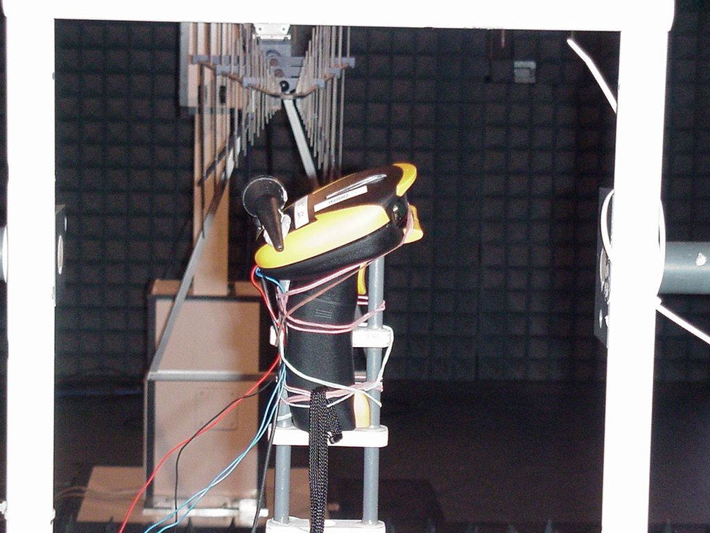
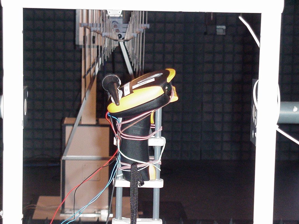
EMC Measurement/Technical Report on 4_Barac_0104_BTT_FCCb 7 Layers AG Borsigstr. 11 40880 Ratingen Germany Note: The following test results relate only to the devices specified in this document. This report shall not be reproduced in parts without the written approval of the testing laboratory. Bluetooth (R) Transceiver BC 2604 -F (Imager) 7 layers AG, Borsigstrasse 11 40880 Ratingen, Germany Phone: +49 (0) 2102 749 0 Fax: +49 (0) 2102 749 350 http://www.7Layers.com Aufsichtsratsvorsitzende Chairman of the Supervisory Board: Dr. Sabine Grobecker Vorstand - Board of Directors: Dr. Hans-Jürgen Meckelburg Registergericht - registered in: Düsseldorf, HRB 44096 USt-IdNr VAT Nr: DE 203159652 Report Reference: TTI-P-G 178/99 Test Laboratory (Headquarter): Interlab is a registered trademark of 7 layers AG with AC/DC power supplySun fone ACTN-25 Table of Contents 0. Summary 0.1 Technical Report Summary 0.2 Measurement Summary 1. Administrative Data 1.1 Testing Laboratory 1.2 Project Data 1.3 Applicant Data 1.4 Manufacturer Data 3. Testobject Data 3.1 General EUT Description 3.2 EUT Main Components 3.3 Ancillary Equipment 3.4 EUT Setups 3.5 Operating Modes 4. Test Results Conducted Emissions Occupied Bandwidth Peak Power Output Spurious RF Conducted Emissions 5. Testequipment 6. Foto Report 7. Setup Drawings 3 3 4 6 6 6 6 6 8 8 9 9 9 10 11 11 13 15 17 24 27 31 33 Spurious RF Radiated Emissions 19 2. Product Labeling 2.1 FCC ID Label 2.2 Location of Label on the EUT 7 7 7 Dwell Time Power Density Channel Separation Processing Gain - - 23 - 4.1 4.2 4.3 4.4 4.5 4.6 8. Annex Annex to test report1 Pages Page 2 of 45Testreport Reference: 4_Barac_0104_BTT_FCCb 0 Summary 0.1 Technical Report Summary Type of Authorization Certification for an Intentional Radiator (Frequency Hopping Spread Spectrum) Applicable FCC Rules: Prepared in accordance with the requirements of FCC Rules and Regulations as listed in 47 CFR Ch.1 Parts 0 to 19 (10-1-98 Edition). The following subparts are applicable to the results in this test report. Part 2, Subpart J - Equipment Authorization Procedures, Certification Sections Part 15, Subpart C - Intentional Radiators § 15.201 Equipment authorization requirement § 15.207 Conducted limits § 15.209 Radiated emission limits; general requirements § 15.247 Operation within the bands 902-928 MHz, 2400-2483,5 MHZ and 5725-5850 MHz Summary Test Results: The EUT complied with all the applicable FCC rules as listed above. Note: The tests were selected and performed with reference to the FCC Public Notice DA 00- 705, released March 30, 2000 Page 3 of 45 Testreport Reference: 4_Barac_0104_BTT_FCCb 0.2 Measurement Summary § 15.207FCC Part 15, Subpart C ANSI C63.41992 The measurement was performed according to Conducted Emissions (AC Power Line) OP-ModeSetupPortFinal Result 1Xs20a03op-mode 5AC IN of power supplypassed § 15.247 (a) (1) (ii)FCC Part 15, Subpart C ANSI C63.41992 The measurement was performed according to Occupied Bandwidth OP-ModeSetupPortFinal Result 1Xs20a02op-mode 1temporary antenna connectorpassed 1Xs20a02op-mode 2temporary antenna connectorpassed 1Xs20a02op-mode 3temporary antenna connectorpassed § 15.247 (b) (1)FCC Part 15, Subpart C FCC §15.3110-1-1998The measurement was performed according to Peak Power Output OP-ModeSetupPortFinal Result 1Xs20a02op-mode 1temporary antenna connectorpassed 1Xs20a02op-mode 2temporary antenna connectorpassed 1Xs20a02op-mode 3temporary antenna connectorpassed § 15.247 (c)FCC Part 15, Subpart C FCC §15.3110-1-1998 The measurement was performed according to Spurious RF Conducted Emissions OP-ModeSetupPortFinal Result 1Xs20a02op-mode 1temporary antenna connectorpassed 1Xs20a02op-mode 2temporary antenna connectorpassed 1Xs20a02op-mode 3temporary antenna connectorpassed § 15.247 (c), §15.35 (b), § 15.209FCC Part 15, Subpart C ANSI C63.41992 The measurement was performed according to Spurious Radiated Emissions OP-ModeSetupPortFinal Result 1Xs20b02op-mode 1enclosurepassed 1Xs20b02op-mode 2enclosurepassed 1Xs20b02op-mode 3enclosurepassed § 15.247 (a) (1)FCC Part 15, Subpart C FCC §15.3110-1-1998 The measurement was performed according to Channel Separation OP-ModeSetupPortFinal Result 1Xs20b02op-mode 4integral antennapassed Page 4 of 45Testreport Reference: 4_Barac_0104_BTT_FCCb Responsible for Accreditation Scope: Responsible for Test Report: Page 5 of 45Testreport Reference: 4_Barac_0104_BTT_FCCb 1. Administrative Data 1.1 Testing Laboratory Company Name: Address: The test facility is also accredited by the following accreditation organisation: Responsible for Accreditation Scope: 7 Layers AG Borsigstr. 11 40880 Ratingen Germany DAR-Registration no. TTI-P-G 178/99 Dipl.-Ing Bernhard Retka Dipl.-Ing Arndt Stöcker Dipl.-Ing Thomas Hoell This facility has been fully described in a report submitted to the FCC and accepted under the registration number 96716. - Deutscher Akkreditierungs Rat 2004-05-18 Dipl.-Ing. Robert Machulec 2004-08-03 2004-07-02 to 2004-07-23 Responsible for testing and report: Receipt of EUT: Date of Test(s): Date of Report: 1.2 Project Data Baracoda Wireless Technology Mickaël Bouffaut 36 rue de Turin 75008 Paris France Zebex Felix Liang B1-1, No. 207 , Sec 3, Beisin Rd., Sindian City, Taipei 231 Taiwan 1.4 Manufacturer Data Company Name: Address: Contact Person: Company Name: Address: Contact Person: 1.3 Applicant Data Page 6 of 45 Testreport Reference: 4_Barac_0104_BTT_FCCb 2.0 Product Labeling 2.1 FCC ID Label: At the time of this report there was no label available. 2.2 Location of Label on the EUT: see above Page 7 of 45Testreport Reference: 4_Barac_0104_BTT_FCCb 3. Testobject Data Type Designation: Kind of Device: (optional) Voltage Type: Voltage level: Equipment under Test: BC 2604 -F (Imager) Barcode Scanner Bluetooth (R) Transceiver DC (2 batteries) 2.4 V Ports 3.1 General EUT Description General product description: Bluetooth is a short-range radio link intended to be a cable replacement between portable and/or fixed elect…
Text truncated - open the document above for the full version.
Test Report
Registergerichth registered in:Vorstandh Board of Directors:7 layers AG, Borsigstrasse 11 Ratingen HRB 3264Dr. Wolfgang Dahm40880 Ratingen, Germany AufsichtsratsvorsitzendehDr. Hans-Jürgen MeckelburgPhone: +49 (0) 2102 749 0 Chairman of the Supervisory Board:Fax: +49 (0) 2102 749 350 Dr. Sabine Grobeckerwww.7layers.com Annex Additional declaration part according FCC 15.247 for Bluetooth TM Devices Version: 2002-06-01 Annex - Additional declaration part according FCC 15.247 for Bluetooth devices Page 2 of 5 pages 1 Output power and channel separation of a Bluetooth device in the different operating modes: The different operating modes (data-mode, acquisition-mode) of a Bluetooth device don’t influence the output power and the channel spacing. There is only one transmitter which is driven by identical input parameters concerning these two parameters. Only a different hopping sequence will be used. For this reason the check of these RF parameters in one op-mode is sufficient. 2 Frequency range of a Bluetooth device: Hereby we declare that the maximum frequency of this device is: 2402 – 2480 MHz. This is according the Bluetooth Core Specification (+ critical errata) for devices which will be operated in the USA. This was checked during the Bluetooth Qualification tests (Test Case: TRM/CA/04-E). Other frequency ranges ( e.g. for Spain, France, Japan) which are allowed according the Core Specification are not supported by this device. 3 Co-ordination of the hopping sequence in data mode to avoid simultaneous occupancy by multiple transmitters: Bluetooth units which want to communicate with other units must be organised in a structure called piconet. This piconet consist of max. 8 Bluetooth units. One unit is the master the other seven are the slaves. The master co-ordinates frequency occupation in this piconet for all units. As the master hop sequence is derived from its BD address which is unique for each Bluetooth device, additional masters intending to establish new piconets will always use different hop sequences. 4 Example of a hopping sequence in data mode: Example of a 79 hopping sequence in data mode: 40, 21, 44, 23, 42, 53, 46, 55, 48, 33, 52, 35, 50, 65, 54, 67, 56, 37, 60, 39, 58, 69, 62, 71, 64, 25, 68, 27, 66, 57, 70, 59, 72, 29, 76, 31, 74, 61, 78, 63, 01, 41, 05, 43, 03, 73, 07, 75, 09, 45, 13, 47, 11, 77, 15, 00, 64, 49, 66, 53, 68, 02, 70, 06, 01, 51, 03, 55, 05, 04 Annex - Additional declaration part according FCC 15.247 for Bluetooth devices Page 3 of 5 pages 5 Equally average use of frequencies in data mode and behaviour for short transmissions: The generation of the hopping sequence in connection mode depends essentially on two input values: 1. LAP/UAP of the master of the connection 2. Internal master clock The LAP (lower address part) are the 24 LSB’s of the 48 BD_ADDRESS. The BD_ADDRESS is an unambiguous number of every Bluetooth unit. The UAP (upper address part) are the 24 MSB’s of the 48 BD_ADDRESS. The internal clock of a Bluetooth unit is derived from a free running clock which is never adjusted and is never turned off. For synchronisation with other units only offset are used. It has no relation to the time of the day. Its resolution is at least half the RX/TX slot length of 312.5 μs. The clock has a cycle of about one day (23h30). In most case it is implemented as 28 bit counter. For the deriving of the hopping sequence the entire LAP (24 bits), 4 LSB’s (4 bits) (Input 1) and the 27 MSB’s of the clock (Input 2) are used. With this input values different mathematical procedures (permutations, additions, XOR- operations) are performed to generate the sequence. This will be done at the beginning of every new transmission. Regarding short transmissions the Bluetooth system has the following behaviour: The first connection between the two devices is established, a hopping sequence was generated. For transmitting the wanted data the complete hopping sequence was not used. The connection ended. The second connection will be established. A new hopping sequence is generated. Due to the fact that the Bluetooth clock has a different value, because the period between the two transmission is longer (and it cannot be shorter) than the minimum resolution of the clock (312.5 μs). The hopping sequence will always differ from the first one. 6 Receiver input bandwidth and behaviour for repeated single or multiple packets: The input bandwidth of the receiver is 1 MHz. In every connection one Bluetooth device is the master and the other one is the slave. The master determines the hopping sequence (see chapter 5). The slave follows this sequence. Both devices shift between RX and TX time slot according to the clock of the master. Additionally the type of connection (e.g. single or multislot packet) is set up at the beginning of the connection. The master adapts its hopping frequency and its TX/RX timing according to the packet type of the connection. Also the slave of the connection will use these settings. Repeating of a packet has no influence on the hopping sequence. The hopping sequence generated by the master of the connection will be followed in any case. That means, a repeated packet will not be send on the same frequency, it is send on the next frequency of the hopping sequence. Annex - Additional declaration part according FCC 15.247 for Bluetooth devices Page 4 of 5 pages 7 Dwell time in data mode The dwell time of 0.3797s within a 30 second period in data mode is independent from the packet type (packet length). The calculation for a 30 second period is a follows: Dwell time = time slot length * hop rate / number of hopping channels *30s Example for a DH1 packet (with a maximum length of one time slot) Dwell time = 625 μs * 1600 1/s / 79 * 30s = 0.3797s (in a 30s period) For multislot packet the hopping is reduced according to the length of the packet. Example for a DH5 packet (with a maximum length of five time slots) Dwell time = 5 * 625 μs * 1600 * 1/5 *1/s / 79 * 30s = …
Text truncated - open the document above for the full version.
Test Report
Registergerichth registered in:Vorstandh Board of Directors:7 layers AG, Borsigstrasse 11 Ratingen HRB 3264Dr. Wolfgang Dahm40880 Ratingen, Germany AufsichtsratsvorsitzendehDr. Hans-Jürgen MeckelburgPhone: +49 (0) 2102 749 0 Chairman of the Supervisory Board:Fax: +49 (0) 2102 749 350 Dr. Sabine Grobeckerwww.7layers.com Annex Additional declaration part according FCC 15.247 for Bluetooth TM Devices Version: 2002-06-01 Annex - Additional declaration part according FCC 15.247 for Bluetooth devices Page 2 of 5 pages 1 Output power and channel separation of a Bluetooth device in the different operating modes: The different operating modes (data-mode, acquisition-mode) of a Bluetooth device don’t influence the output power and the channel spacing. There is only one transmitter which is driven by identical input parameters concerning these two parameters. Only a different hopping sequence will be used. For this reason the check of these RF parameters in one op-mode is sufficient. 2 Frequency range of a Bluetooth device: Hereby we declare that the maximum frequency of this device is: 2402 – 2480 MHz. This is according the Bluetooth Core Specification (+ critical errata) for devices which will be operated in the USA. This was checked during the Bluetooth Qualification tests (Test Case: TRM/CA/04-E). Other frequency ranges ( e.g. for Spain, France, Japan) which are allowed according the Core Specification are not supported by this device. 3 Co-ordination of the hopping sequence in data mode to avoid simultaneous occupancy by multiple transmitters: Bluetooth units which want to communicate with other units must be organised in a structure called piconet. This piconet consist of max. 8 Bluetooth units. One unit is the master the other seven are the slaves. The master co-ordinates frequency occupation in this piconet for all units. As the master hop sequence is derived from its BD address which is unique for each Bluet…
Text truncated - open the document above for the full version.
Contact Information
Applicant
Thierry Fortune(Project Manager)
Technical Contact
BARACODA Wireless TechnologyLudovic Wauthy
[email protected]+33 143873898
36, Rue de Turin · Paris · France
Non-Technical Contact
BARACODA Wireless TechnologyOlivier Giroud
[email protected]+33 143873898
Test Firm
7layers AGRobert Machulec
Technical Specifications
| # | Rule Parts | Frequency Range | Power Output |
|---|---|---|---|
| 1 | 15C | 2.40 GHz - 2.48 GHz | 20.14 mW |
Other Applications from XIRING SA
QSHAIOKTD
May 23, 2012Bluetooth Barcode Scanner with RFID
Equipment Class
DSS - Part 15 Spread Spectrum Transmitter
QSHAIOKTB
May 23, 2012Bluetooth Barcode Scanner
Equipment Class
DSS - Part 15 Spread Spectrum Transmitter
QSHAIBSW
Dec 25, 2007Baracoda Scanwear Bluetooth Wireless Scanner
Equipment Class
DSS - Part 15 Spread Spectrum Transmitter
QSHAIBTR
Dec 25, 2007Baracoda TOUGHRUNNERS Bluetooth Wireless Scanner
Equipment Class
DSS - Part 15 Spread Spectrum Transmitter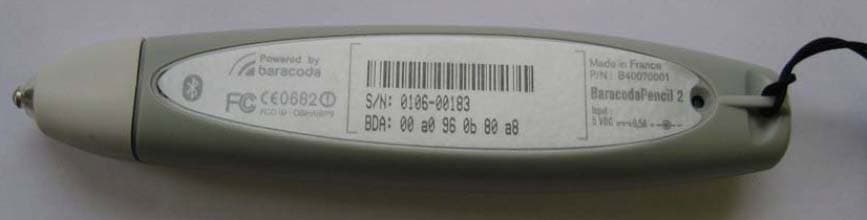
QSHAIBP2
Feb 27, 2007BarecodaPencil2 - Bluetooth Barcode Scanner
Equipment Class
DSS - Part 15 Spread Spectrum Transmitter