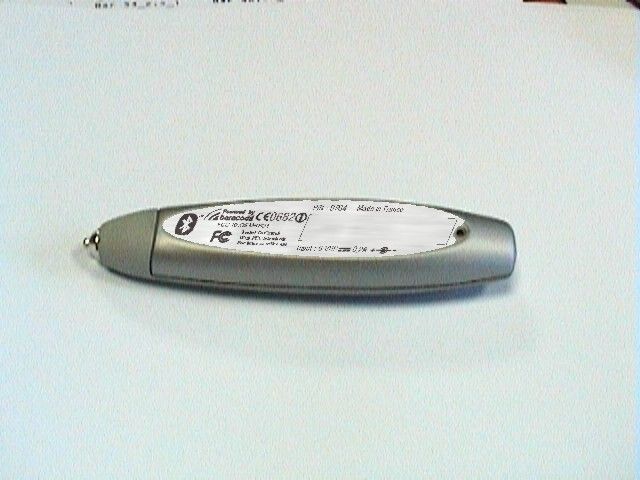
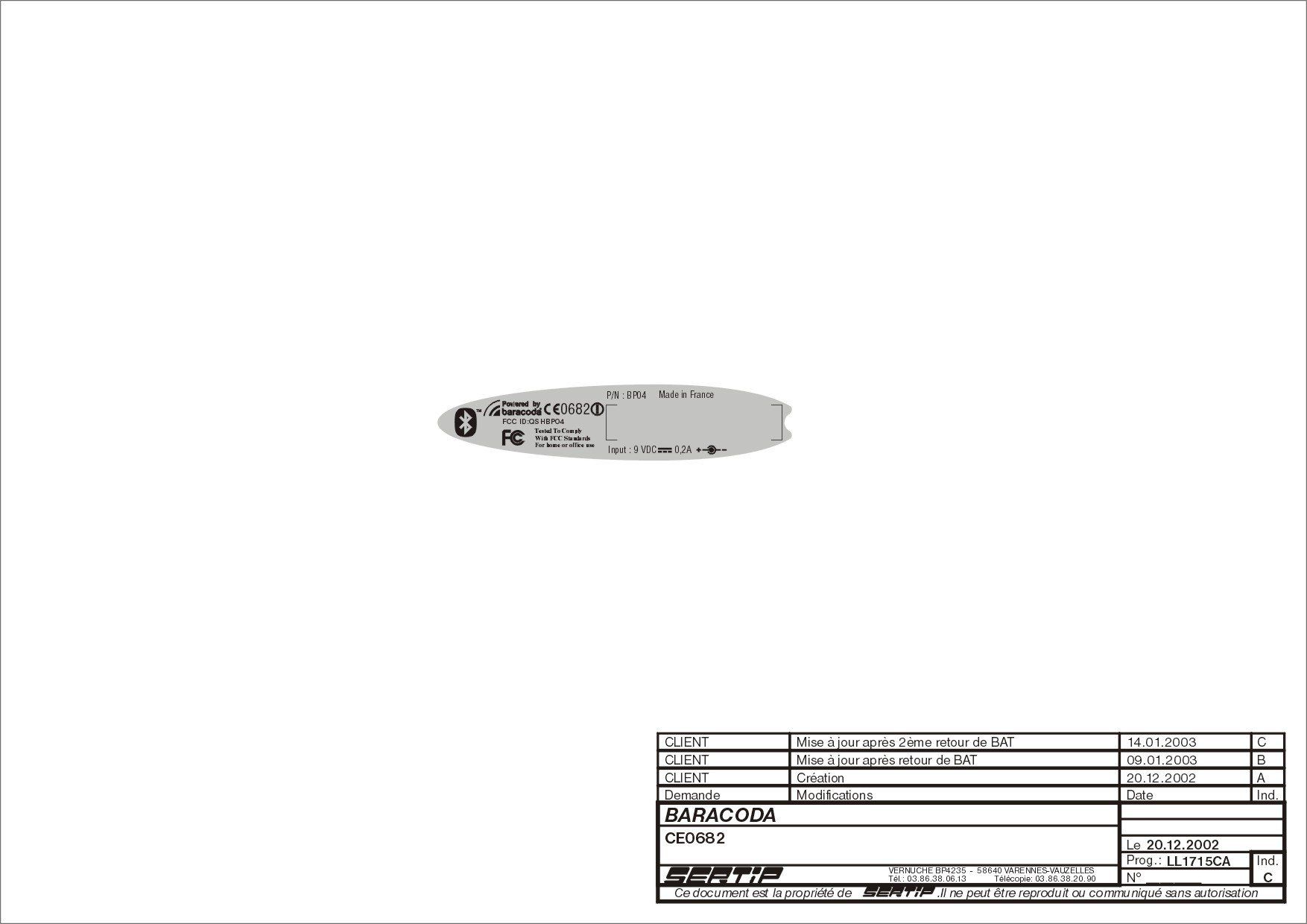
QSHBP04Bluetooth Barcode Reader Pen
XIRING SA
Click to zoom
Application Details
- Equipment Class
- DSS - Part 15 Spread Spectrum Transmitter
- Date of Grant
- Jan 29, 2003
- Application Purpose
- Original Equipment
- Date of Application
- Jan 29, 2003
- Equipment Note
- Bluetooth Barcode Reader Pen
- Frequency Range
- 2402.00000000 - 2480.00000000
- Company
- XIRING SA
- Country
- France
Documents & Files
Document Text
Text extracted from the exhibit documents filed with the FCC. Open a document above to read the original.
Users Manual
BaracodaPencil™ User Guide 1. Package contents Check to make sure you have the following items. Contact your supplier if any item is missing. • 1 BaracodaPencil • 1 Battery charger 110-230V/9V 200mA • 1 User’s Guide 2. BaracodaPencil Interface BaracodaPencil is designed for easy use. You simply press a button when scanning a barcode. The color of the LED (red, green or yellow) shows the status of the device. You can also find a Reset button, located on the back; this button can help you to reset the default parameters, if necessary (should you experience further problems, please contact our Customer Support, at [email protected]). BaracodaPencil can process several types of barcodes: EAN/UPC, Code 39 or Code 128. The bar codes are transmitted either in real time or memorized for later transmission, to remote terminals which use the Bluetooth protocol. You can download decoding algorithms updates from http://www.baracoda.com Pictures below show the BaracodaPencil features: Bouton Tête de lecture LED Bicolore LED Bicolore Connecteur de recharge 3. User’s Guide 3.1 Usage modes 2 usages modes are possible: 3.1.1 Real Time Mode In “Real Time mode”, the barcode is decoded and transmitted immediately to a remote device. 3.1.2 Batch Mode In “Batch mode”, the barcode is read and stored in the BaracodaPencil non-volatile memory*, for later transmission. This memory can contain up to 1,000 barcodes. *Non-volatile memory: when the BaracodaPencil is turned off, data is saved in memory. 3.1.3 Mode selection “Real Time mode” is the default mode. To switch to “Batch mode”, download the Baracoda configuration software from http://www.baracoda.com 3.2 Real Time Use To use the BaracodaPencil: • Check all connections. • Keep pressing the button during the scan. • Make sure that the BaracodaPencil tip is in physical contact with the barcode as long as the scan lasts. 3.2.1 Connecting the BaracodaPencil to a remote device This connection phase opens a communication channel between the barcode reader and a remote device. • To connect the BaracodaPencil, turns it on by pressing the button. The blinking green LED indicates that the BaracodaPencil is awaiting a connection. If no connection is made within 3 minutes, the BaracodaPencil switches off automatically. • Use the Bluetooth software provided with your Bluetooth device to detect the BaracodaPencil (See the Bluetooth device documentation). • Search for available services. • Enter the default PIN code: 0000. You can change this default code using the Baracoda configuration software. • Connect the two devices using the Serial Port Profile (SPP). When the BaracodaPencil is connected, the SPP icon turns green. BaracodaPencil connected with SPP • When the BaracodaPencil is connected, the green LED blinks twice as fast. • After one hour of inactivity, the BaracodaPencil automatically disconnects from the Bluetooth device and switches off. • When you are done with the BaracodaPencil, close the SPP connection. The green LED blinks again at a slower rate. 3.2.2 Reading a barcode To scan: • Position the barcode reader tip a few millimeters ahead of the barcode, • Press and hold the button. The tip emits a red light, indicating that the BaracodaPencil is ready to scan, • Scan the barcode from left to right OR from right to left (as if you were highlighting the barcode), • The LED flashes green for 0.5 seconds if the scan is complete. • The LED flashes red for 0.5 seconds if the scan fails. In this case, you must redo the operation. LED verte LED rouge 3.2.3. Automatic connection through the BaracodaPencil The BaracodaPencil memorizes the address of the last device to which it was connected. A successful scan triggers an automatic connection to this device. The LED blinks green when the connection is made. The LED blinks yellow if no connection is possible: either the device is turned off or is out of range. In this case, the BaracodaPencil switches automatically to “Batch mode”. See "Batch mode" below. 3.3. “Batch mode” use for later transmission In “Batch mode”, the barcode is read and stored in memory, for later transmission to a remote device. To operate in batch mode: • Turn on the BaracodaPencil. The LED blinks green. • Use the Baracoda configuration software to set the BaracodaPencil to “Batch mode”. A yellow blinking LED indicates "Batch mode". • Scan the barcodes: - The LED turns green for 0.5 seconds if the barcode is read, - The LED turns red for 0.5 seconds if the operation has failed. - When the LED is yellow, the memory is full. To clear the memory, create a connection with a device and use the Baracoda configuration software. 3.4. Other functions 3.4.1 Low Battery The BaracodaPencil is supplied with a charger. 3 periodical red blinks of the LED indicate that the battery level is low. You can continue to use the BaracodaPencil until it turns off by itself. To recharge the battery, connect the charger into the battery plug (see 2-BaracodaPencil interface, ‘Battery connector’). The LED remains red while the battery is charging. A full recharge takes about 2 hours. You cannot use the BaracodaPencil during the charging period. Remember to turn off the Bluetooth connection before recharging the battery. 3.4.2 Battery Manager In order to economize the battery power, the BaracodaPencil automatically breaks the Bluetooth connection and turns off after six minutes of inactivity in connected mode and 20 minutes in disconnected mode. 4.BaracodaPencil Status Display The status of the LED Indicates the BaracodaPencil status Green blinking BaracodaPencil is on, awaiting a connection Fast green blinking BaracodaPencil is connected to remote device One 0.5 seconds green flash Barcode is decoded One 0.5 seconds red flash Barcode cannot be decoded Yellow blinking "Batch mode" is set 1 Yellow flash Full memory 3 red blinks Low battery Constant red light Battery charging 5. Technical Specifications BaracodaPencil v1.0 General Interface: Radio. Bluetooth 1.1 Recognized Code…
Text truncated - open the document above for the full version.
Cover Letter(s)
attn: Reviewing Engineer Federal Communications Commission 7435 Oakland Mills Road Columbia, MD 21046 RE: 15.19 STATEMENT FOR BaracodaPencil (FCC ID: QSHBP04) To Whom It May Concern: Due to the small size of the equipment the statement specified in Section 15.19 can not be placed in the equipment. This statement is placed in a prominent location in the instruction manual. Please contact me if there is any information you may need. Signed by Olivier Giroud CTO Baracoda Wireless Technology 2003-01-22
Cover Letter(s)
attn: Reviewing Engineer Federal Communications Commission 7435 Oakland Mills Road Columbia, MD 21046 RE: CONFIDENTIALITY REQUEST FOR BaracodaPencil (FCC ID: QSHBP04) To Whom It May Concern: This letter serves as an official request for confidentiality under FCC Rule Section 0.459. We have requested that the schematic diagrams and block diagrams required to be submitted with this application be withheld from public review. Those documents are company proprietary information that could never get into the possession of our competitors. Please contact me if there is any information you may need. Signed by Olivier Giroud CTO Baracoda Wireless Technology 2003-01-22
Cover Letter(s)
attn: Reviewing Engineer Federal Communications Commission 7435 Oakland Mills Road Columbia, MD 21046 RE: LETTER OF AGENT AUTHORIZATION To Whom It May Concern: We, the undersigned, hereby authorize MET Laboratories, Inc. to act on our behalf in all matters relating to application for equipment authorization (FCC ID: QSHBP04), including the signing of all documents relating to these matters. We also hereby certify that no party to the application authorized hereunder is subject to the denial of benefits, including FCC benefits, pursuant to Section 5301 of the Anti-Drug Abuse Act of 1988,21 U.S.C.853(a). This agreement expires one year from the current date. Sincerely, Signed by Olivier Giroud CTO Baracoda Wireless Technology 2003-01-22
Operational Description
Operational description RF Receiver The receiver features a near-zero Intermediate Frequency (IF) architecture that allows the channel filters to be integrated on to the die. Sufficient out-of-band blocking specification at the Low Noise Amplifier (LNA) input allows the radio to be used in close proximity to Global System for Mobile Communications (GSM) and Wideband Code Division Multiple Access (W-CDMA) cellular phone transmitters without being desensitised. The use of a digital Frequency Shift Keying (FSK) discriminator means that no discriminator tank is needed and its excellent performance in the presence of noise allows BlueCore2-External to exceed the Bluetooth requirements for co-channel and adjacent channel rejection. Low Noise Amplifier The LNA can be configured to operate in single-ended or differential mode. Single-ended mode is used for Class 1 Bluetooth operation; differential mode is used for Class 2 operation. Analogue to Digital Converter The Analogue to Digital Converter (ADC) is used to implement fast Automatic Gain Control (AGC). The ADC samples the Received Signal Strength Indicator (RSSI) voltage on a slot-by-slot basis. The front-end LNA gain is changed according to the measured RSSI value, keeping the first mixer input signal within a limited range. This improves the dynamic range of the receiver, improving performance in interference limited environments. RF Transmitter IQ Modulator The transmitter features a direct IQ modulator to minimise the frequency drift during a transmit timeslot which results in a controlled modulation index. A digital baseband transmit filter provides the required spectral shaping. Power Amplifier The internal Power Amplifier (PA) has a maximum output power of +6dBm allowing BlueCore2-External to be used in Class 2 and Class 3 radios without an external RF PA. Support for transmit power control allows a simple implementation for Class 1 with an external RF PA. RF Synthesiser The radio synthesiser is fully integrated onto the die with no requirement for an external Voltage Controlled Oscillator (VCO) screening can, varactor tuning diodes or LC resonators. Baseband and Logic Memory Management Unit The Memory Management Unit (MMU) provides a number of dynamically allocated ring buffers that hold the data which is in transit between the host and the air or vice versa. The dynamic allocation of memory ensures efficient use of the available Random Access Memory (RAM) and is performed by a hardware MMU to minimise the overheads on the processor during data/voice transfers. Burst Mode Controller During radio transmission the Burst Mode Controller (BMC) constructs a packet from header information previously loaded into memory-mapped registers by the software and payload data/voice taken from the appropriate ring buffer in the RAM. During radio reception, the BMC stores the packet header in memory- mapped registers and the payload data in the appropriate ring buffer in RAM. This architecture minimises the intervention required by the processor during transmission and reception. Physical Layer Hardware Engine DSP Dedicated logic is used to perform the following: • Forward error correction • Header error control • Cyclic redundancy check • Encryption • Data whitening • Access code correlation • Audio transcoding RAM 32Kbytes of on-chip RAM is provided and is shared between the ring buffers used to hold voice/data for each active connection and the general purpose memory required by the Bluetooth stack. External Memory Driver The External Memory Driver interface can be used to connect to the external Flash memory and also to the optional external RAM for memory intensive applications. USB This is a full speed Universal Serial Bus interface for communicating with other compatible digital devices. BlueCore2-External acts as a USB peripheral, responding to requests from a Master host controller such as a PC. Synchronous Serial Interface This is a synchronous serial port interface for interfacing with other digital devices. The SPI port can be used for software debugging and for programming the external Flash memory. UART This is a standard Universal Asynchronous Receiver Transmitter (UART) interface for communicating with other serial devices. Audio PCM Interface The Audio Pulse Code Modulation (PCM) Interface supports continuous transmission and reception of PCM encoded audio data over Bluetooth. Microcontroller The microcontroller, interrupt controller and event timer run the Bluetooth software stack and control the radio and host interfaces. A 16-bit Reduced Instruction Set Computer (RISC) microcontroller is used for low power consumption and efficient use of memory. Programmable I/O BlueCore2-External has a total of 15 (12 digital and 3 analogue) programmable I/O terminals. These are controlled by firmware running on the device.
RF Exposure Info
Federal Communication Commission Authorization and Evaluation Division 7435 Oakland Mills Road Columbia, MD 21046 Attention: Reviewing Engineer RF exposure information The BaracodaPencil is a portable device with a built-in Bluetooth radio module using spread spectrum technique. Due to the construction of the BaracodaPencil and the position of the internal antenna (it’s placed on the centre of the device) a distance under normal operating conditions of more than 1cm can be expected. Due to the low power of the device (less than 2.5 mW) the MPE limits can be guaranteed as the calculation below shows: EIRPmax = 4 dBm = 2.5 mW The worst case transmit duty cycle for only data Bluetooth device would be the transmission of DH5 packets in a piconet with just one additional user. This is shown as the bottom row in figure below. For DH5 packets the transmitter transmits across five 625 microsecond slots minus a guard band of 259 microseconds. The transmission is followed by a 625 microsecond receive slot. The transmission duty cycle (Tdc) for this case can be calculated as: (625 * 5) – 259 Tdc = 625 * 6 Tdc = 76% The average power for DH5 packets would be: EIRPmax X 0.76 = 1.9 mW = +2.79 dBm Using the equation from OET Bulletin 65 to estimate the distance from the antenna: R = (EIRP/4πS) 1/2 Where, R = distance to the centre of radiation of the antenna in cm S = power density in mW/cm2 (1 mW/cm2 used for BaracodaPencil) EIRP = effective isotropically radiated power in mW (2.5 for BaracodaPencil) R = 0.39 cm Therefore the 1 mW/cm2 requirement is not exceeded unless the body is less than 0.39 cm from the BaracodaPencil antenna. In normal operation of BaracodaPencil, and due the construction characteristics of the equipment (antenna is centred inside of a plastic enclosure of more than 2 cm of diameter), the body will be more than 1 cm from the antenna. So that, the BaracodaPencil meets the MPE limits.
Test Report
Annex to test report # 17566RET.101: EIRP clarification Annex to test report 17566RET.101: EIRP clarification The radiated EIRP was checked several times the measured EIRP showed in the test report # 17566RET.101 is accurate. The measured EIRP was much lower than the theoretical EIRP.
Test Report
Annex to test report # 17566RET.101: Radiated emission data for emissions in Restricted Bands Annex to test report # 17566RET.101: Radiated emission data for emissions in Restricted Bands Spurious emissions of the transmitter was measured all over the spectrum. Special attention was taken in the emissions in the Restricted bands, including spurious emissions at the upper bandedge, in the 2483.5 – 2500 MHz restricted band, and the second and third harmonics. The only spurious signals found in the Restricted Bands were the ones indicated in page 30 of test report # 17566RET.101. No spurious signals were found within the 2483.5 – 2500 MHz restricted band and spurious at 2 nd and 3 rd harmonics were not found either.
Test Report
15.247 (a) (1) Statement CETECOM S.A. – ITA team Page 1 of 16 Bluetooth devices 15.247 (a) (1) Statement Bluetooth devices Date: 27/01/2003 15.247 (a) (1) Statement CETECOM S.A. – ITA team Page 2 of 16 Bluetooth devices 1. Pseudorandom hop selection The generation of the hopping sequence in connection mode depends essentially on two input values: 1. LAP/UAP of the master of the connection 2. Internal master clock The LAP (lower address part) are the 24 LSB’s of the 48 BD_ADDRESS. The BD_ADDRESS is an unambiguous number of every Bluetooth unit. The UAP (upper address part) are the 24 MSB’s of the 48 BD_ADDRESS. The internal clock of a Bluetooth unit is derived from a free running clock which is never adjusted and is never turned off. For synchronisation with other units only offset are used. It has no relation to the time of the day. Its resolution is at least half the RX/TX slot length of 312.5 μs. The clock has a cycle of about one day (23h 30’). In most case it is implemented as 28 bit counter. For the deriving of the hopping sequence the entire LAP (24 bits), 4 LSB’s (4 bits) (Input 1) and the 27 MSB’s of the clock (Input 2) are used. With this input values different mathematical procedures (permutations, additions, XOR-operations) are performed to generate the sequence. This will be done at the beginning of every new transmission. The output constitutes a pseudorandom sequence covering 79 hop channels. The exact procedures for the generation of the pseudorandom hopping sequence can be found in “Bluetooth specification Version 1.1 – Part B – Baseband Specification – Chapter 11: Hop selection”. The following is a sample of a pseudorandom hopping sequence of 20 sec. 32000 hops): 34 72 31 69 28 66 25 63 22 60 19 57 16 54 13 51 10 48 07 45 04 42 01 39 77 36 74 33 71 30 68 27 65 24 62 21 59 18 12 20 09 17 61 20 58 17 00 08 76 05 49 08 46 05 67 75 64 72 37 75 34 72 55 63 52 60 25 63 22 60 43 51 40 48 13 51 10 48 31 39 28 36 01 39 77 36 19 27 16 24 68 27 65 24 70 29 55 14 64 23 49 08 58 17 43 02 52 11 37 75 34 72 43 02 28 66 37 75 20 09 17 06 14 03 11 00 22 60 07 45 16 54 01 39 76 65 73 62 70 59 67 56 78 37 63 22 72 31 57 16 66 25 51 10 60 19 45 04 42 01 51 10 36 74 45 04 28 17 25 14 22 11 19 08 30 68 15 53 24 62 09 47 18 56 03 41 12 50 76 35 73 32 03 41 67 26 76 35 59 48 56 45 53 42 50 39 61 20 46 05 55 14 40 78 49 08 34 72 43 02 28 66 25 63 34 72 19 57 28 66 52 62 49 59 46 56 43 53 40 50 37 47 34 44 31 41 28 38 25 35 22 32 19 29 12 50 09 47 61 48 58 45 77 08 09 19 47 06 58 17 67 26 64 23 37 24 34 21 53 63 64 74 23 61 34 72 31 69 14 52 49 59 32 42 19 57 02 40 37 47 20 30 72 31 04 42 11 21 22 32 62 49 59 46 01 39 77 36 58 45 41 28 52 39 35 22 59 69 56 66 29 67 26 64 47 57 44 54 17 55 14 52 35 45 32 42 05 43 02 40 23 33 20 30 72 31 69 28 11 21 08 18 60 19 57 16 78 09 75 06 48 07 45 04 66 76 63 73 36 74 33 71 38 76 21 59 32 70 15 53 26 64 09 47 20 58 03 41 00 38 11 49 73 32 05 43 69 56 66 53 63 50 60 47 69 28 52 11 63 22 46 05 78 37 75 34 44 33 41 30 72 01 77 06 38 76 43 02 60 68 65 73 26 64 31 69 56 64 45 53 22 60 11 49 30 68 27 65 75 64 72 61 24 32 29 37 69 28 74 33 12 20 17 25 57 16 62 21 63 22 60 19 57 16 54 13 37 26 42 31 31 20 36 25 39 77 36 74 33 71 30 68 13 02 18 07 07 75 12 01 15 53 12 50 09 47 06 44 14 52 11 49 59 48 56 45 08 16 13 21 53 12 58 17 75 04 01 09 41 00 46 05 71 00 60 68 37 75 26 64 45 04 42 01 11 00 08 76 39 47 44 52 05 43 10 48 27 35 32 40 72 31 77 36 78 37 75 34 72 31 69 28 52 41 57 46 46 35 51 40 54 13 51 10 48 07 45 04 28 17 33 22 22 11 27 16 30 68 27 65 24 62 21 59 35 73 32 70 29 67 26 64 27 37 32 42 21 31 26 36 15 25 20 30 09 19 14 24 13 51 02 40 56 43 45 32 01 39 69 28 44 31 33 20 60 19 65 24 24 11 29 16 60 70 57 67 24 62 21 59 18 56 15 53 42 52 39 49 73 60 78 65 18 56 23 61 73 32 70 29 18 28 15 25 49 36 54 41 73 32 78 37 51 38 48 35 45 32 42 29 14 52 11 49 38 48 35 45 02 40 78 37 26 36 23 33 69 28 66 25 14 24 11 21 59 46 56 43 53 40 50 37 59 18 48 07 53 12 42 01 35 22 32 19 29 16 26 13 35 73 24 62 29 67 18 56 09 47 06 44 33 43 30 40 76 35 73 32 21 31 18 28 64 23 61 20 09 19 06 16 52 11 49 08 76 07 73 04 42 29 39 26 36 23 33 20 77 06 66 74 43 02 32 70 57 65 62 70 23 61 28 66 39 77 36 74 05 73 02 70 41 49 30 38 07 45 75 34 29 37 15.247 (a) (1) Statement CETECOM S.A. – ITA team Page 3 of 16 Bluetooth devices 18 26 74 33 63 22 09 17 14 22 54 13 59 18 70 29 67 26 36 25 33 22 72 01 61 69 38 76 27 65 60 68 49 57 26 64 15 53 40 48 45 53 06 44 11 49 22 60 19 57 67 56 64 53 24 32 13 21 69 28 58 17 50 39 47 36 72 31 69 28 52 11 41 00 74 03 63 71 40 78 29 67 62 70 51 59 18 07 23 12 12 01 17 06 06 74 11 00 00 68 05 73 02 70 70 59 75 64 64 53 75 34 72 31 69 28 66 25 51 10 56 15 73 02 78 07 33 22 30 19 55 14 52 11 35 73 24 62 57 65 46 54 23 61 12 50 45 53 34 42 01 69 06 74 74 63 00 68 32 42 19 27 71 30 68 27 10 18 07 15 59 18 56 15 77 06 74 03 47 06 44 03 65 73 62 70 35 73 32 70 53 61 50 58 23 61 20 58 59 18 56 15 53 12 50 09 47 06 44 03 41 00 38 76 35 73 32 70 29 67 26 64 23 61 20 58 17 55 14 52 11 49 08 46 05 43 02 40 78 37 75 34 72 31 69 28 66 25 63 22 60 19 57 16 54 13 51 10 48 07 45 04 42 01 39 77 36 74 33 71 30 68 27 65 24 62 21 59 18 56 15 53 12 50 09 47 06 44 03 41 00 38 76 35 47 34 30 17 41 28 24 11 33 71 30 68 27 65 24 62 23 10 06 72 17 04 00 66 09 47 06 44 03 41 00 38 78 65 61 48 72 59 55 42 64 23 61 20 58 17 55 14 54 41 37 24 48 35 31 18 56 66 67 77 26 64 37 75 46 05 43 02 16 03 13 00 46 56 29 39 16 54 78 37 34 44 17 27 04 42 66 25 08 18 19 29 57 16 68 27 20 58 17 55 38 48 35 45 08 46 05 43 26 36 23 33 75 34 72 31 14 24 11 21 59 46 56 43 53 40 50 37 45 04 56 15 39 77 50 09 35 22 32 19 29 16 26 13 21 59 32 70 15 53 26 64 15 53 12 50 33 43 30 40 03 41 00 38 21 31 18 28 70 29 67 26 09 19 06 16 58 17 55 14 76 07 73 04 42 29 39 26 36 23 33 20 20 28 25 33 65 24 70 29 16 24 05 13 61 20 50 09 69 28 66 25 35 24 32 21 63 71 68 76 29 67 34 72 51 59 56 64 17 55 22 60 47 55 36 44 13 51 02 40 21 59 18 56 66 55 63 52 15 23 20 28 60 19 65 24 03 11 08 16 48 07 53 12 78 07 67 75 44 03…
Text truncated - open the document above for the full version.
Test Report
15.247 (g) Statement CETECOM S.A. – ITA team Page 1 of 1 Bluetooth devices 15.247 (g) Statement – Bluetooth devices Date: 27/01/2003 According to Bluetooth specifications the channel hopping sequence which has a very long period length (23h 30’) does not show repetitive patterns over a short time interval, but distributes the hop frequencies equally over the 79 hopping channels during a short time interval. The generation of the hopping sequence in connection mode depends essentially on two input values: 1. LAP/UAP of the master of the connection 2. Internal master clock The LAP (lower address part) are the 24 LSB’s of the 48 BD_ADDRESS. The BD_ADDRESS is an unambiguous number of every Bluetooth unit. The UAP (upper address part) are the 24 MSB’s of the 48 BD_ADDRESS. The internal clock of a Bluetooth unit is derived from a free running clock which is never adjusted and is never turned off. For synchronisation with other units only offset are used. It has no relation to the time of the day. Its resolution is at least half the RX/TX slot length of 312.5 μs. The clock has a cycle of about one day (23h 30’). In most case it is implemented as 28 bit counter. For the deriving of the hopping sequence the entire LAP (24 bits), 4 LSB’s (4 bits) (Input 1) and the 27 MSB’s of the clock (Input 2) are used. With this input values different mathematical procedures (permutations, additions, XOR-operations) are performed to generate the sequence. This will be done at the beginning of every new transmission. The output constitutes a pseudorandom sequence covering 79 hop channels. For short transmissions the Bluetooth systems have the following behaviour: When the first connection between two devices is established, a hopping sequence is generated. If for transmitting the wanted data the complete hopping sequence is not used, the connection is ended. When a second connection is established. A new hopping sequence is generated. Due to the fact that the Bluetooth clock has a different value, because the period between the two transmission is longer (it cannot be shorter) than the minimum resolution of the clock (312,5 μs). The hopping sequence will always differ from the first one.
Test Report
Report No.: 17566RET.101 Date: 2002-12-12 Page: 2 of 8 FDT08_04 INDEX 1. COMPETENCE AND GUARANTEES ........................................................................................... 3 2. GENERAL CONDITIONS ............................................................................................................... 3 3. CHARACTERISTICS OF THE TEST ............................................................................................. 3 3.1 TEST REQUESTED.................................................................................................................. 3 3.2 REQUIREMENTS AND METHOD ......................................................................................... 3 4. IDENTIFICATION DATA SUPPLIED BY THE APPLICANT ..................................................... 5 4.1 APPLICANT.............................................................................................................................. 5 4.2 REPRESENTATIVE ................................................................................................................. 5 4.3 TEST SAMPLES SUPPLIER.................................................................................................... 5 4.4 IDENTIFICATION OF ITEM/ITEMS TESTED ...................................................................... 5 5. USAGE OF SAMPLES, PERIOD OF TESTING AND ENVIRONMENTAL CONDITIONS ...... 6 5.1 USAGE OF SAMPLES ............................................................................................................. 6 5.2 PERIOD OF TESTING.............................................................................................................. 6 5.3 ENVIROMENTAL CONDITIONS........................................................................................... 6 6. TEST RESULTS............................................................................................................................... 8 7. REMARKS AND COMMENTS ...................................................................................................... 8 8. SUMMARY ...................................................................................................................................... 8 ANNEXES ANNEX A. TEST RESULTS ANNEX B. PHOTOGRAPHS Report No.: 17566RET.101 Date: 2002-12-12 Page: 3 of 8 FDT08_04 1. COMPETENCE AND GUARANTEES Centro de Tecnología de las Comunicaciones (CETECOM), S.A. is a laboratory with a measurement facility in compliance with the requirements of Section 2.948 of the FCC rules and has been added to the list of facilities whose measurements data will be accepted in conjuction with applications for Certification under Parts 15 or 18 of the Commission's Rules. Registration Number: 905266. In order to assure the traceability to other national and international laboratories, CETECOM has a calibration and maintenance programme for its measuring equipment. CETECOM guarantees the reliability of the data presented in this report, which is the result of measurements and tests performed to the item under test on the date and under the conditions stated on the report and is based on the knowledge and technical facilities available at CETECOM at the time of execution of the test. CETECOM is liable to the client for the maintenance by its personnel of the confidentiality of all information related to the item under test and the results of the test. 2. GENERAL CONDITIONS 1.This report only refers to the item that has undergone the test. 2.This report does not constitute or imply by its own an approval of the product by the Certification Bodies or competent Authorities. 3.This document is only valid if complete; no partial reproduction can be made without written approval of CETECOM. 4.This test report cannot be used partially or in full for publicity and/or promotional purposes without previous written approval of CETECOM and the Accreditation Bodies. 3. CHARACTERISTICS OF THE TEST 3.1 TEST REQUESTED Measurements for frequency hopping equipment (Bluetooth ) operating in the 2400 MHz -2483.5 MHz band and using, according to FCC Part 15.247. 3.2 REQUIREMENTS AND METHOD The test has been carried out according to FCC parts 15.33, 15.35, 15.205, 15.209, 15.247 and the document DA 00-705:"Filing and Measurement Guidelines for Frequency Hopping Spread Spectrum Systems". The testing was performed according to the procedure in ANSI C63.4 (1992). Radiated testing was performed in Cetecom's semi-anechoic chamber. This site has been fully described in a report submitted to the FCC and was accepted in a letter dated July 25, 2002. Report No.: 17566RET.101 Date: 2002-12-12 Page: 4 of 8 FDT08_04 The instrumentation used to perform the testing is listed below: 1.Semianechoic Absorber Lined Chamber IR 11. BS. 2.Control Chamber IR 12.BC. 3.Spectrum Analyzer HP 8566 B. 4.RF Preselector HP 85685A. 5.Quasi-peak adaptor HP 85650A. 6.RF linear amplifier HP 8447.F 7.Antenna mast EM 1072 NMT. 8.Rotating table EM 1084-4. ON. 9.Mast controller EM 1053-22. 10.Rotating table controller EM 1064-4023. 11.Process controller HP 98581C. 12.Harddisk HP 9153. 13.Peripheral unit HP 9153 C. 14.Measurement software HP 85879A. 15.3 dB attenuator HP 8491A. 16.Bilog antenna CHASE CBL6111. 17.Bilog antenna CHASE CBL6111. 18.Antenna tripod EMCO 11968C. 19.Double-ridge Guide Horn antenna 1-18 GHz HP 11966E. 20.Double-ridge Guide Horn antenna 18-40 GHz Agilent 119665J. 21.Switch Unit with RF pre-amplifiers R&S TS8930SU. 22.RF pre-amplifier Miteq JS4-12002600-30-5A. 23.EMI Test Receiver R&S ESIB26. Report No.: 17566RET.101 Date: 2002-12-12 Page: 5 of 8 FDT08_04 4. IDENTIFICATION DATA SUPPLIED BY THE APPLICANT Identificaton data in this section has been supplied by the client. 4.1 APPLICANT Name or Company: BARACODA WIRELESS TECHNOLOGY V.A.T.: FR 64428768600 Address: 55, Avenue Auguste Renoir (Marly Le-Roi) Postal code: F 78160Country: FRANCE Telephone: +33 1 30088900Fax: +33 1 39168063 4.2 REPRESENTATIVE Name: Mickaël Bouffaut 4.3 T…
Text truncated - open the document above for the full version.
Test Report
Report No: 17566RET.101 Date: 2002-12-12 Page: 18 of 36 Annex A FET45_00.DOC PEAK OUTPUT POWER (RA…
Text truncated - open the document above for the full version.
Contact Information
Applicant
Thierry Fortune(Project Manager)
Technical Contact
MET Laboratories Inc.Christopher Harvey
[email protected]410-354-3300
914 W. Patapsco Avenue · Baltimore, Maryland · United States
Non-Technical Contact
MET Laboratories Inc.Marianne Bosley
[email protected]410-354-3300
Test Firm
Centro de Tecnologia de las Comunicaciones, S.A.Alejandro Llamas
Technical Specifications
| # | Rule Parts | Frequency Range | Power Output |
|---|---|---|---|
| 1 | 15C | 2.40 GHz - 2.48 GHz | 200.00 µW |
Other Applications from XIRING SA
QSHAIOKTD
May 23, 2012Bluetooth Barcode Scanner with RFID
Equipment Class
DSS - Part 15 Spread Spectrum Transmitter
QSHAIOKTB
May 23, 2012Bluetooth Barcode Scanner
Equipment Class
DSS - Part 15 Spread Spectrum Transmitter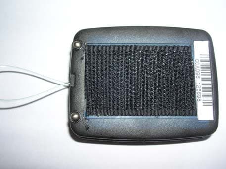
QSHAIBSW
Dec 25, 2007Baracoda Scanwear Bluetooth Wireless Scanner
Equipment Class
DSS - Part 15 Spread Spectrum Transmitter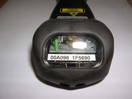
QSHAIBTR
Dec 25, 2007Baracoda TOUGHRUNNERS Bluetooth Wireless Scanner
Equipment Class
DSS - Part 15 Spread Spectrum Transmitter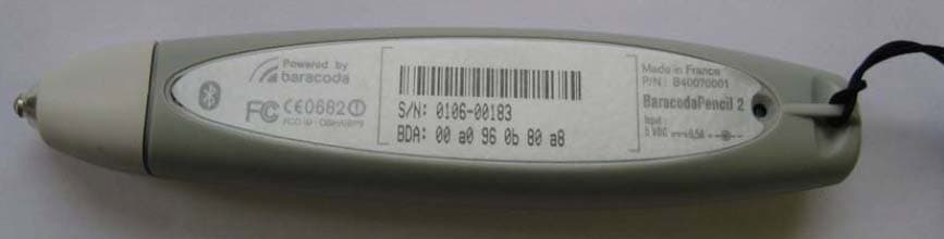
QSHAIBP2
Feb 27, 2007BarecodaPencil2 - Bluetooth Barcode Scanner
Equipment Class
DSS - Part 15 Spread Spectrum Transmitter