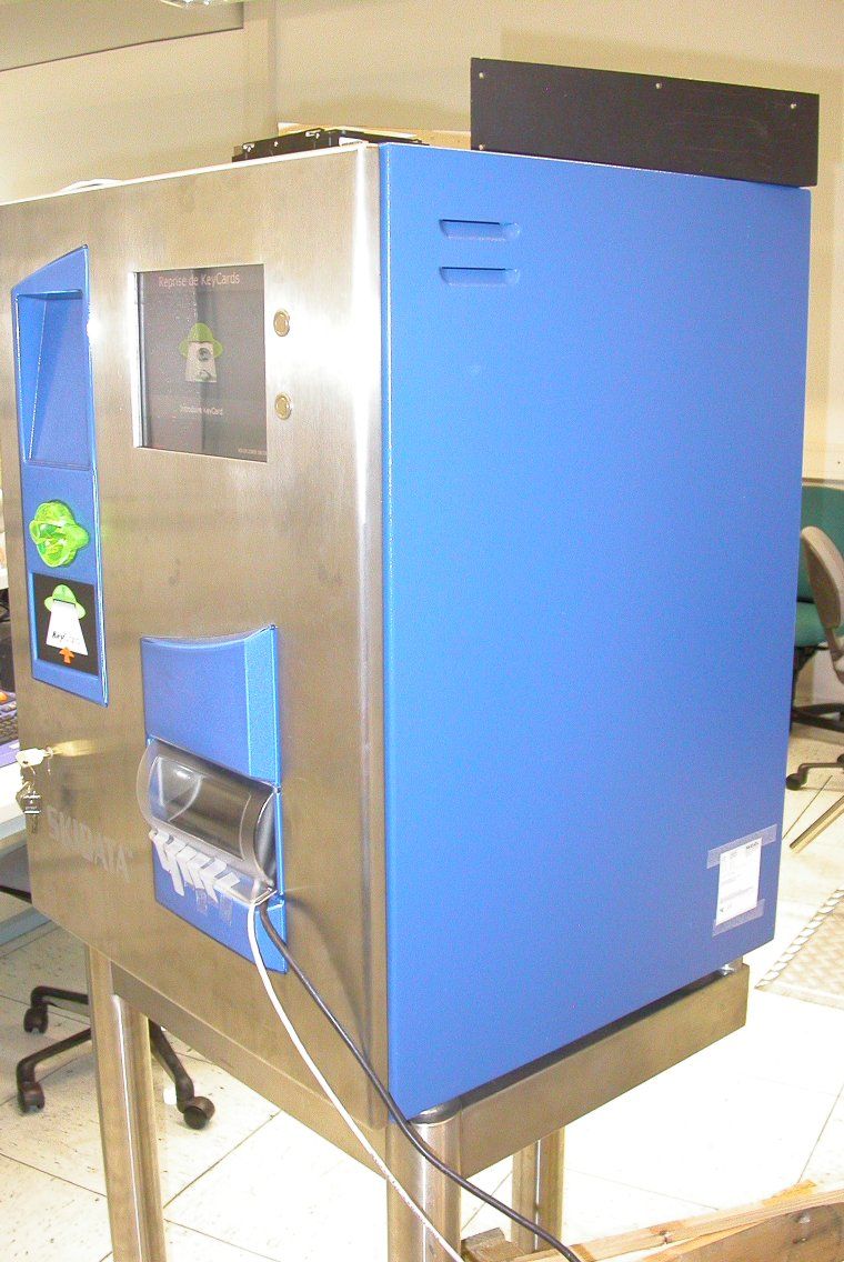
QSS-KC370IAUT2Keycard return machine including RFID
Skidata AG
Click to zoom
Application Details
- Equipment Class
- DXT - Part 15 Low Power Transceiver, Rx Verified
- Date of Grant
- Jan 12, 2005
- Application Purpose
- Original Equipment
- Date of Application
- Jan 12, 2005
- Equipment Note
- Keycard return machine including RFID
- Frequency Range
- 13.55300000 - 13.56700000
- Company
- Skidata AG
- Country
- Austria
Documents & Files
Document Text
Text extracted from the exhibit documents filed with the FCC. Open a document above to read the original.
Users Manual
Manual and operational description keycard Return Machine KC 370i AUT2 Manual and operational description keycard Return Machine Page 2 © SKIDATA AG, December 2004 SKIDATA AG Technical Documentation Untersbergstrasse 40 A-5083 Gartenau Telephone +43 6246 888 - 0 Telefax +43 6246 888 - 7 Internethttp://www.skidata.com [email protected] Copyright © 2004 by SKIDATA AG. All rights reserved. All information in the following document is protected by copyright law. No part of this document may be reproduced without the written consent of SKI- DATA AG. SKIDATA AG reserves the right to make any changes of specification and other information in this document without further notice. Please note During the compilation of this Technical Documentation, great care has been taken to ensure the accuracy of the information contained in it. However, despite our constant effort to ensure the highest degree of accuracy and comprehensiveness possible, the information provided cannot be guaranteed to be absolutely error-free. Trademarks This documentation may contain representations of registered product or service trademarks owned by SKIDATA AG or third parties, as well as references to proprietary know-how protected by copyright laws or other legal provisions. In any case the intel- lectual property rights remain exclusively with their respective owners. Declaration of Conformity The keycard-Return Machine KC 370i AUT2 has been devel- oped, designed and manufactured in accordance with the follow- ing EU directive: R&TTE (1999/5/EC) 0408 Version December 2004 Keycard Return Machine Manual and operational description © SKIDATA AG, December 2004 Page 3 FCC 15.19: This device complies with Part 15 of the FCC Rules. Operation is subject to the following two conditions: (1) this device may not cause harmful interference, and (2) this device must accept any interference received, including interference that may cause un- desired operation. FCC 15.21: IMPORTANT: Any changes to or modifications of keycard Return Machine unless expressly approved by SKIDATA™, may void the user's authority to operate this device. Manual and operational description keycard Return Machine Page 4 © SKIDATA AG, December 2004 Keycard Return Machine 1 Document Management – Version Table Tab. 1: Document Version Table for Installation & Maintenance Instructions SectionDocumentPagesVersionDate 1 Keycard Return Machine 4 1.0 2004-12-07 Keycard – Return Machine 7 1 keycard Return Machine 48 Pages Copyright 2004 by SKIDATA AG 7 keycard Return Machine 1.1Contents Page 2 © SKIDATA AG, Version 1.0 1.1 Contents 1.1Contents 2 1.2Description 4 1.3Operation 5 1.3.1Returning keycards 5 1.3.2Returning keycards with remaining credits 6 1.4Service functions 7 1.4.1Login 7 1.4.2Service menu 8 1.4.2.1Reset 9 1.4.2.2Download Firmware 9 1.5Info Terminal 10 1.5.1Searching the event log 11 1.5.2Key Number 13 1.6Dimensions 15 1.7Front View & Description of Components 16 1.7.1Keycard Return Machine – dimensions 17 1.7.2Mounting 18 1.7.2.1Mounting on wall mounting brackets 18 1.7.3Mounting on rack stand 22 1.8Power Connections 24 1.8.1Connecting control board sd412 25 1.8.2Strain relief 26 1.8.3Heater 28 1.9PC connections 30 1.9.1Connectors 30 1.9.2IPC connections (rear) 31 1.10Replacing the keycard Container 32 1.10.1Removing the keycard container 32 1.10.2Inserting the keycard container 34 1.10.3Inserting the coin cashbox 36 1.10.4Removing the coin cashbox 37 1.11Dispenser 38 1.12Preparing IPC Settings 43 1.12.1Keyboard rest 43 1.12.2Swivelling the monitor 44 keycard Return Machine 7 Contents1.1 © SKIDATA AG, Version 1.0 Page 3 1.13Replacing the Mechanism 46 1.14Closing the Bolted-open Door 47 7 keycard Return Machine 1.2Description Page 4 © SKIDATA AG, Version 1.0 1.2 Description The keycard Return Machine verifies the keycard inserted by the guest and pays out the pre-defined deposit in coins or banknotes, depending on the machine version. Cash can be refilled by means of easy-to-change cashboxes. The device is controlled through an integrated PC that stores all transactions and device status details. Peripherals such as a mouse, keyboard and swivel-out monitor are provided for easy servicing. The software offers a multi-lingual graphical user interface for easy, efficient control. Networking the keycard Return Machines via Ethernet or modem lines allows for remote maintenance and polling of counters and logs (transaction tracing). If a container needs replacing, the machine can automatically send a message to pre-defined devices (e.g., POS stations). The End-of-Day records are relayed to the DataCentral for inclusion in the overall statistical evaluation. keycard Return Machine 7 Operation1.3 © SKIDATA AG, Version 1.0 Page 5 1.3 Operation 1.3.1 Returning keycards The following screen message indicates that the keycard Return Machine is fully operational and ready: A keycard may now be inserted into the ticket slot. Once the card has been verified and accepted, the deposit is paid out into the change dish. Fig. 1: Return procedure 7 keycard Return Machine 1.3Operation Page 6 © SKIDATA AG, Version 1.0 1.3.2 Returning keycards with remaining credits When inserted into the front slot of the machine, the keycard is read and verified. Any remaining credits (points, hours, etc.) will be indicated on the screen: The card holder may then decide whether or not to return the card anyway. Pressing the ‘Yes’ button will initiate the return procedure; pressing the ‘No’ button will abort the procedure and return the card to the holder. Fig. 2: Remaining credits keycard Return Machine 7 Service functions 1.4 © SKIDATA AG, Version 1.0 Page 7 1.4 Service functions There are two basic ways of accessing the Service menu: 1.4.1 Login Logging on without keyboard When performing simple maintenance tasks such as refilling dispensers or hoppers, it is possible to access the unit using a service card instead of entering a password with the keyboard. Insert the service card into the…
Text truncated - open the document above for the full version.
Cover Letter(s)
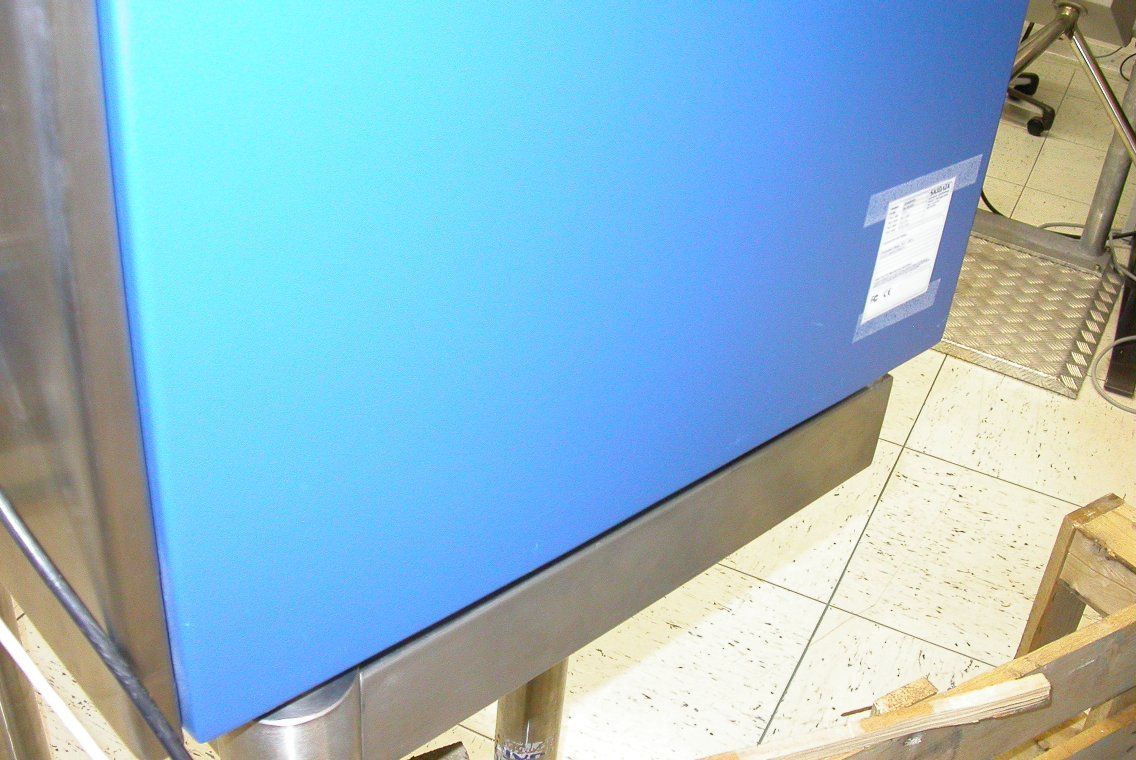
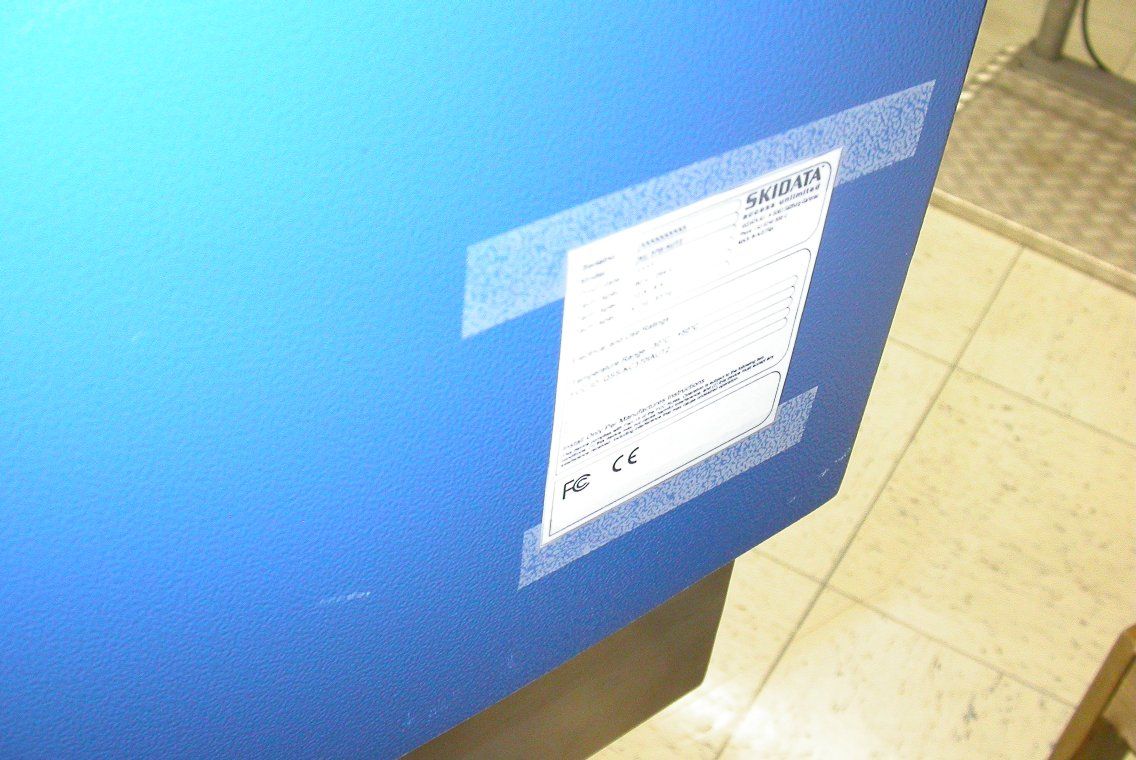
Coverletter: SKIDATA AG wants to get FCC-Certification for the following product: Keycard Return Machine “KC 370i AUT2” The unit will get the following FCC-ID: QSS-KC370IAUT2 List of documents: Exhibit Thema File Exhibit 01 Label and placement Type_Label_KC_370i_AUT2.pdf Type label position 1.jpg Type label position 2.jpg Type label position 3.jpg Exhibit 02 Not needed -------------------- Exhibit 03 External Photos extern_05-104.pdf * Exhibit 04 Block Diagrams Block Diagram entire machine.pdf Block Diagram mechanics.pdf * Exhibit 05 Schematic Diagrams sd412_2.pdf sd537_7.pdf sd553_2.pdf Exhibit 06 Testreport 05-104.pdf Exhibit 07 Test Set-up Photos setup_05-104.pdf Exhibit 08 User Manual Manual keycard Return Machine.pdf Exhibit 09 Internal Photos intern_05-104.pdf Exhibit 10 Not needed -------------------- Exhibit 11 Not needed -------------------- Exhibit 12 Operational Description Fact sheet keycard Return Machine.pdf Exhibit 13 Cover letter Request for confidentiality This file Confidentiality_KC_370i_AUT2.pdf For the Exhibits marked with ‘*’ SKIDATA AG requested Confidentiality according to 47 CFR 0.457 and 0.459 of the FCC rules because these are sensitive parts owned by this company and include much of Know-How or sensitive data, it will not be provided to the public. The labelling on some photos may not be the actual status. The correct labelling you can see on the pdf document in Exhibit 1.
Cover Letter(s)
Fa. SKIDATA AG Untersbergstrasse 40 A-5183 Gartenau / Salzburg Austria, Europe Tel.: +43 6246 888-0 Fax: +43 6246 888-7 Gartenau, 2005-01-05 TÜV Österreich (TUEV Austria) Deutschstrasse 10 A-1230 Wien Austria, Europe Tel.: +43 1 61091-0 Request for CONFIDENTIALITY Pursuant to 47 CFR 0.457(d) of the FCC Rules, we have request for confidentiality of the following parts of our documentation regarding the keycard Return Machine “KC 370i AUT2” (FCC-ID: QSS-KC370IAUT2): • Schematic Diagrams: - sd412_2.pdf - sd537_7.pdf - sd553_2.pdf • Block Diagrams: - Block Diagram entire machine.pdf - Block Diagram mechanics.pdf This information is owned by our company and put into public is prohibited. We further certify that the applicant nor any party to the application subject to a denial of Federal benefits, that includes FCC benefits, pursuant to Section 5301 of the Anti-Drug Abuse Act of 1988, 21 U.S.C Section 862. Christoph Sonderegger Standard Compliance Coordinator SKIDATA AG
External Photos
Appendix 2 Photodocumentation Description: General view TUt! ÖSTERREICI MedlzlntechnlklNach. richc8 actw IiklEMV D8pInm8IC EMC Test report reference: M/EMV -0511 04 PIle: 1 cl21 DIte: 13.012005 -~~
Internal Photos
Appendix 2 Photodocumentation Description: Open view TU'! ÖSTERREIC MedizintechniklNach- richtentechniklEMV Department: EMC Test report ref'erence: I'\IEMV .Q5/1 04 Page: 2 0(21 Date: 13.01.2005 ~~ Page: 2 of21 Appendix 2 Photodocumentation Description: Collection tray TU" ÖSTERREIC Medizintechnlk/Nach- richtentechniklEMV DepInment: EHC Test report reference: MlEMV-O5I104 PIle: 3 of21 Date: 13.011iZL . chedcedbr-? Appendix 2 Photodocumentation Description: Display general TU'! ÖSTERREIC Medizintechnik/Nach. richtent8chnik/EMV DepInment: EHe Test report reference: MIEMV -0511 04 PIae: '4 of21 =:~ Appendix 2 Photodocumentation Description: Display open TDy ÖSTERREIC Medlzlntechnilc/Nach- richtehtechnikJEMV DepartmentEMC T 1St report reference: MIEMV -0511 ()4 PIp: 5 0( 21 Date: 13.O1.200S checked by.11 ?** Appendix 2 Photodocumentation Description: Display PCB #1 TiJ~ ÖSTERREIC MedizintechnllclNach- richtentecho IiklEMV DepartmInt: EHe Test report reference: M/EMV -0511 ()4 Pace: 6 of21 Date: 13.01 ~ checkedby.~ Appendix 2 Photodocumentation Description: Display PCB #2 TUt! OSTERREIC Medizlntechnik/Nach- richtentechnIk/ Departmenc EHe Test report reference: MIEMV -0511 04 PIle: 7 0(21 Date: 13.01.2~ checked by. L..hI.. , 1O1.2O1J ...,-116 Appendix 2 Photodocumentation Description: Display power supply model plate TU" ÖSTERREIC MedizintechnlklNach- richtellt8Ch.lik/EMV Department: EMC Test report reference: MIEMV ~1 04 Pace: 8 of 21 DatE 13.012005 checbdby:~ ~ Appendix 2 Photodocumentation Description: Power supply general view TiJV ÖSTERREIC MedizintechniklNach- richtentechnik/EMV DepartmentEMC Test report reference: MIEMV -OSI1 04 Pqe: 90121 Date: 1 3.01.2005 chedcedby.fHu,. Ifh* Appendix 2 Photodocumentation Descrlption: Power supply model plate TiJt/ ÖSTERREICI MedizintechnlklNach- rlchtentechniklEMV DepInJ ,181t: EI'1C Test report reference: MlEMV-O5I104 "10 d21 Appendix 2 Photodocumentation Description: sd412 general view TU'! ÖSTERREIC MedizintechniklNach- richteI.ted8likIEMV DIpartmInt: EHe Test report reference: 1"1'EMV~5I1 04 "'11of21 Date: 13.011005 chedced by. LJd Appendix 2 Photodocumentati on Description: sd412 component side TU" ÖSTERREIC MedizinteehniklNach- richtentechnik/EMV DepIrtmIm: EMC Test report reference: MlEMV-O5I104 "120(21 Appendix 2 Photodocumentation Description: sd412 solder side TU" ÖSTERREIC MedizintechnlklNach- richtel.t8ChniklEMV [)epartmII1t: EMC Test report reference: MIEMV -051104 Paae: 13 0(21 Date: 13.01 i1 ~ ~~r Appendix 2 -. . Photodocumentation Descripdon: PC TUV ÖSTERREIC Medlzintechnik/Nach- rtchtentechnlkJEMV Department EHC Test report reference: MlEMV -0511 ()4 .'4 of2' D8te: 13.01 Llu. """""""rr Appendix 2 Photodocumentation Description: PC connections TD~ ÖSTERREIC MedizlntechniWNach- richtelltechnikIEMV DepInrnIIIt: EMC Test report reference: MIEMV ~5J1 04 .150(21 Date: 13.011i2".. chedcedbr-r Appendix 2 Photodocumentation Description: PC open view TU'! ÖSTERREIC MedizintechnikINach- richtentechnill/EMV Depanment: EMC Test report reference: M/EMV-OS/1O4 PIle: 160(21 D.te: 1 3.01.2~ chedc8dby.r Appendix 2 Photodocumentation Description: PC power supply TiJV ÖSTERREIC Medlzlntechnlk/Nach- ric:htentechnik/EMV Depanment: EHe Test report reference: M/EMV ~1 04 PIle: 17 d21 Date: 13.011~ checbdbr-r Appendix 2 Photodocumentation Description: PC model plate TUV ÖSTERREIC Medizlntechni k/Nach. rlcht8ttechniIclEMV DepInment: EHe Test report referenc~ MIEMV.o5I1O4 Paae: 18 0(21 =:~ Appendix 2 Photodocumentation Description: Mechanie ME 360 general view TU" ÖSTERREICI MedilintechnikiNach- richtentechnik/EMV Depanment: EHe Test report reference: MJEMV .QSI1 04 Pale: 19 of21 Date: 13.01.2il. chedcedby:f"'t Appendix 2 Photodocumentation Description: detail TU ÖSTERREIC Medizlntechnik/Nach- richt8ltechniklEMV DepInmenc EMC Test report reference: MIEMV ~1 04 PIle: 20 cf 21 D8te: 13.01 ~ -"'r
Operational Description
:-):-) :-):-) :-) SKIDATA AG • Untersbergstraße 40 • A-5083 Gartenau [t] +43 (0) 62 46/8 88-0 • [f] +43 (0) 62 46/8 88-7 • [e] [email protected] • [w] www.skidata.com Version 1.0 • 13.10.2003 • Copyright © 2003 by SKIDATA AG This documentation may contain representations of registered product or service trademarks owned by SKIDATA AG or third parties, as well as references to proprietary know-how protected by copyright laws or other legal provisions. In any case the intellectual property rights remain exclusively with their respective owners. This document is subject to change without notice. It cannot form part of a binding contract. Picture may vary from actual product keycard Return MachinePage 1/2 KC 370i AUT2 The keycard Return Machine validates inserted keycards and returns the appropriate deposit either in coins or in banknotes, depending on the model. Cash refilling is by way of easy-to-handle, replaceable cashboxes. The Return Machine is controlled by an internal PC that stores all transactions and status details. A swivelling monitor, mouse, and keyboard are provided to ensure easy servicing. The monitor provides graphical user guidance in several languages. When running Version 12 or higher of the Data Central operating software, the device can be connected to the Data Central via an Ethernet or dial-up connection, allowing for remote maintenance and retrieval of counter readings and system logs (e.g., searching for specific transactions). Whenever the cash box needs replacing, the device automatically sends messages to a pre- defined list of computers (e.g., POS Terminals). End- of-day reports are relayed to the Data Central for use in system analyses and reports. Software Version 14 and higher supports central configuration of all networked keycard Return Machines. Properties •Accepts and verifies ISO15693 compatible 122.88 kHz and 13.56 MHz keycards •Cash capacity: Coin Version: up to 2,000 coins, depending on coin size (e.g., 1,500 • 2 coins) Banknote Version: approx. 800 banknotes •Ergonomically designed, illuminated ticket slot •10.4" TFT monitor with two function keys for request confirmation •Integrated industry-standard control PC •Illuminated change tray •Built-in alarm system •Separate insert slots for keycard container and coin/ banknote cashboxes •Compact, durable casing for wall-mounting or installation on a support stand •Thermostat-controlled heating •Manufactured in accordance with ISO 9001 standards Standard Version 937000110 ............................... keycard Return Machine, including monitor and built-in alarm system 937400300 ...............................Control PC (industry standard) 937010200 ...............................Banknote Version: includes keycard container, banknote cashbox, and power adaptor 937010210 ...............................Coin Version: includes keycard container, coin cashbox, and power adaptor 937010212 ...............................Coin Version for coins with diameters greater than 30mm (e.g., Swiss 5-Francs coin) : includes keycard container, coin cashbox, and power adaptor 937010500 ...............................Optional heater (230V) 937010510 ...............................Optional heater (115V) Accessories 936010020 ............................... Tripod type steel support stand 937010700 ............................... 2-part wall-mounting console Note: The console may only be mounted on concrete surfaces using appropriate anchoring fixtures (e.g., Hilti HST dowels M12 / 50). 945010012 ...............................UPS (uninterruptible power supply; 230V only; recommended) 937010250 ...............................Coin replacement cashbox 937010260 ...............................Banknote replacement cashbox Technical Characteristics Dimensions (h x w x d)............. 800 x 630 x 580 mm (approx. 31½ x 23¾ x 22¾ in) Weight (max.)........................... 110 kg (242.5 lb) Colour ....................................... Casing, support stand, and wall-mounting console: blue RELIUS E 14-45; Door (front panel): high-grade steel (1.4301) Power supply........................... 230VAC/50Hz, 115VAC/60Hz Max. power consumption ......... Coin Version: 390W; Banknote Version: 475W , Add-on heater: 300W Operating temperature............. –30°C to +50°C (-22 F to 122 F) keycard Return MachinePage 2/2 KC 371i AUT2 1700 1367 1131 900 800 580 630 centred cable inlet 20
Test Report
1II~-I11~~ . .~; , . , "r~ Applicant Product: Serial Number. Standard: A publication of this test report is only permitted literaJly. Copying or reproduction of partial sections needs a written permiss;on of TÜV Österreich. The results of this test report only refer to the provided equipment. file: ($.104.doc TUt( ÖSTERREICI Division Medical Technologyl Communication Technologyl EMC TEST REPORT of the accredited test laboratory TÜV Nr.:MIEMV-OS/1o.t T esting Body for Communication T echnologyl EMC about the following EMC - test/- research Prüfzentrum Wien A-1230 Wien Deutschstraße 1 0 Tel.: +43 1 /61091 Fax: Ext. 6505 Mail: [email protected]"SKIDA T A AG Untersbergstraße 40 A-5083 Gartenau - St leonhard Accredited T esting Lmoratory, Inspection Body, Certificatjon Body. Calibration Body Keycard Return Machine KC 37Oi AUTI Notified Body 0408 Canada: IC4413 47 CFR Ch.1 Part 15 RSS-21 0 Issue 5 TÜV ÖSterreich Test laboratory for EMC DVR 0047 3j3 . UID ATU 3~ "'1 cf1) 1101. 2OOS Test report runber: M/EMV -0511 04 Date; 13.01. 2005 Contents Designation page Applicant Description of EUT Standards I Final result Test results Conducted emission (15.109); (6.6.) Radiated emission (15.209); (6.21.) Operation within the band 13.110 14,010 MHz Appendix Designation Test equipment used ~1 Photodocumentation 2- 3 Measurement diagrams F'1te: Q5.104.doc TU'! ÖSTERREICI ) .. > 5 6-8 9-11 12.1) 15.225 (a+b+c+d+e); 6.22. (e) pages 3 11 10 Plae2of13 Test report runber: MIEMV-O5I104 Date: 1101. 2005 1. Applicant Company Department Address Contact person Mr. Sonderegger EUT received on 14.09.2004 Tests were performed on 14.09. -17.09.2004 file: 0>104- TUt! ÖSTERREICI SKiDATA AG A-SO83 Gartenau - St leonhard; Untersbergstraße 40 ~~~ Paae 3 er 13 Test report ~ M/EMV .() 511 04 Date: 13.01. 2005 Description of EUT 2. EUt Serial Number Manufacturer Description Operating mode FIle: Q5..104.doc PIle" dU TUt( ÖSTERREICI Keycard Return Machine KC 370i AUTI SKiDA T A AG A-SO83 Gartenau - St leonhard; Untersbergstraße 40 SKIDA T A AG provided the following configuration for the measurements: Serial production The measurements were carried out at the following running states: normal use ~~~ Test report number: MlEMV-O5I1 04 Date: 13.01. 2005 3. Ale: 0S-104.doc Pate S 01'13 - TU ÖSTERREIC result ~4- Test report number. MIEMV -051104 Date: 13.01. 2005 4. Test results -t. 1. Conducted emission Limits according to 15.109 and 6.6. Measuring apparatus parameters: File: O5-104.doc TUt{ ÖSTERREICI- -~~ ,. 6 0(13 T eR report runber: I"\IEMV ~ 04 Date: 13.01. 2005 Test result: 4.1.1.) Measurement with QP-Detec:tor continuous and modulated carrier at 13.56 MHz 4f. 1.2.) Measurement with AV-DetectOr continuous and modulated carrier at 13.56 MHz .. This part of emission is coverd by 15.225 (a) and 6.21(e) File: 05-104.doc Pace 7 0(13 T Mt report 1'1I.mber: MIEMV-OS/104 Date: 1101. 2005 4.1.3.) Measurement with QP-Detector continuous and modulated canier at 122,9 kHz 4.1.4.) Measurement with AV-DeteCtOr continuous and modulated carrier at 122.9 kHz fiIe: 05-1 04 .doc TU" ÖSTERREICI -~~ Page 8 cf 13 Test report runber: MIEMV-O5I104 0.. 13.01. 2005 4. 2. Radiated emission Umits according to 15.209 arId 6.2.1. File: 05-1 04 .doc TU~ ÖSTERREIC. PI&e 9 of 13 Test report m.mber. MlEMV'()5/104 Date: 13.01.2005 Test result: 4. 2.1.) Measurement in the frequency range 9 kHz to 30 MHz continuous and modulated canier at 122.9 kHz 4. 2.2.) Measurement in the frequency range 30 MHz to 18000 MHz continuous and modulated carrier at 122,9 kHz File: Q5.104.doc TU'! ÖSTERREICI Page 10 or13 Test report nuT'lber: I"VEMV -0511 04 Date: 13.01. 2005 <4. 2.3.) Measurement in the frequency range 9 kHz to 30 MHz continuous and modulated canier at 13.56 MHz Due to 1he large margin to the limit. no final measurement was performed. 4. 2.4.) Measurement in ehe frequency range 30 MHz to 18000 MHz continuous and modulated carrier at 13.56 MHz File: 05- 1 04 .doc 11 d 1 J 6STERREIC -~~ Test report nuT1ber. MlEMV-O5I104 Date: 13.01. 2005 4.3. 15.225 Operation within the band 13,110-14.010 MHz RSS-210 6.2.2.(e) 13.553 -13.567 MHz 15.225 (a): The fjeld strength of any emissions within this band shall not exceed 15.848 microvottslmeter (84 dBINlm) at 30 meters. Measurement results: The fjeld strength at 3m distance was measured as 39,9 dB~Nlm. Extrapolated with 40 dB per decade to 30 meters distance it would be -0,1 dB~Nlm. 6.2.2.(e) The fjeld strength of any emissions within this band shall not exceed 15.500 microvoltslmeter (84 dBINlm) at 30 meters. Measurement results: The fjeld strength at 3m distance was measured as 39.9 deiN/mo Extrapolated with 40 dB per decade to 30 meters distance it would be -0,1 dB~Nlm. 15.225 (b) and 6.2.2.(e): Frequency range Level Ü'T1it MHz ~Vlm d8tJVtm 13.410 - 13.553 < 45 90,5 13,567 - 13,710 < 45 90,S The Limit was increased tor a constant measurement distance of 3m with a factor of 40 dB per Oecade. 15.225 (c) and 6.2.2.(e): Frequency range level Umit MHz dB~V/m dB~V/m 13.110...;., 13,410 < 45 80.5 13,710 -14,010 < 45 80.5 The Umit was increased for a constant measurement distance of 3m with a factor of 40 dB per Decade. nie: OS-104.doc TU'! ÖSTERREIC.. --~} "12of13 T 1St report runber: MIEMV..oSl104 CIte: 13.01. 2005 15.225 (d): See measurement diagram. 15.225 (e) and 6.2.2.(e): The fi-equency tolerante of the canier signal shall be maintained within .:t 0,01 % of the operating frequency over a temperature variation ov -20 degrees to +50 degrees C at normal supply voltage. and for a variation of the primary supply voltage from 85 % to 115 % of the rated supply voltage at a temperature of 20 degrees C. For battery operated equipment, the equipment tests shall be performed using a new battery. Measurement results: File: 05-104.doc TUt! ÖSTERREIC Page 13 0( 13 chedced by. Appendix 1 Test equip nt usedme ~ Anechoic Chamber with 3m measurement distance 11 MA 240 - Antenna mast /'I - 4 m height ~ DS 412 - Tumtable eL 0 - 400 0 Azimuth S HO 100…
Text truncated - open the document above for the full version.
Test Setup Photos
Appendix 2 Photodocumentation Description: test setup absorbercharnber ÖSTERREIC MedIz1ntechnlk/Nach- richt8:ltechniIclEMV Department: EMC Test report refetence: MIEHV -0511 04 ... 21 cf 21 CII8: 11O1.200S -~~
Contact Information
Applicant
Christoph Sonderegger(Ing. Mag.)
Test Firm
TUV AustriaIng Wilhelm Seier
Technical Specifications
| # | Rule Parts | Frequency Range | Power Output |
|---|---|---|---|
| 2 | 15C | 13.553 MHz - 13.567 MHz | - |
Other Applications from Skidata AG

QSS-SD805
Nov 15, 2012RFID Reader module sd805
Equipment Class
DXX - Part 15 Low Power Communication Device Transmitter
QSS-SD814
Jul 05, 2012RFID Reader module sd814
Equipment Class
DXX - Part 15 Low Power Communication Device Transmitter
QSS-RDKEY
Mar 04, 2012RFID Reader
Equipment Class
DXX - Part 15 Low Power Communication Device Transmitter
QSS-TRM
Aug 31, 2010RFID Reader
Equipment Class
DXX - Part 15 Low Power Communication Device Transmitter
QSS-SD705
Jul 20, 2006Inductive Tag Reader Module
Equipment Class
DXT - Part 15 Low Power Transceiver, Rx Verified