QUPHJ-DS100FDoor/ Window Sensor
Hyun Joung System Co., Ltd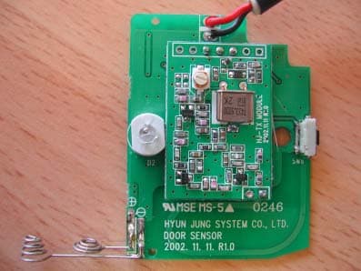
Click to zoom
Application Details
- Equipment Class
- DSC - Part 15 Security/Remote Control Transmitter
- Date of Grant
- Feb 25, 2003
- Application Purpose
- Original Equipment
- Date of Application
- Feb 25, 2003
- Equipment Note
- Door/ Window Sensor
- Frequency Range
- 433.42500000 - 434.41500000
- Company
- Hyun Joung System Co., Ltd
- Country
- South Korea
Documents & Files
Document Text
Text extracted from the exhibit documents filed with the FCC. Open a document above to read the original.
Users Manual
This device complies with Part 15 of the FCC Rules. Operation is subject to the following two conditions: (1) this device may not cause harmful interference, and (2) this device must accept any interference received, including interference that may cause undesired operation. CAUTION: Changes or modifications not expressly approved by the party responsible for compliance could void the user's authority to operate the equipment.
Block Diagram
SAVERCALL-1000 Door/Window Sensor (HJ-DS100F)
External Photos
External Photo Door/Window Sensor
ID Label/Location Info
Label Information <Door/Window Sensor : QUPHJ-DS100F> Label is attached on the rear of product The Label shown shall be permanently affixed at a conspicuous location on the device and be readily visible to the user at the time of purchase. Below Statement is seen on user’s manual THIS DEVICE COMPLIES WITH PART 15 OF THE FCC RULES. OPERATION IS SUBJECT TO THE FOLLOWING TWO CONDITIONS; (1) THIS DEVICE MAY NOT CAUSE HARMFU L INTERFERENCE. AND (2) THIS DEVICE MUST ACCEPT ANY INTERFERENCE RECEIVED. INCLUDING INTERFERENCE THAT MAY CAUSE UNDESIRED OPERATION. FCC ID : QUPHJ-DS100F
Internal Photos
Internal Photo Door/Window Sensor Internal Photo Internal Photo
Operational Description
Operation Manual This product informs emergency situation to user using wired te lephone line when produce invader, fire occur- rence using wireless sensors and emergency situation using wire less remote controller (include necklace style remote controller). And also it is a stand-alone radio alarm sy stem that can drive out invaders. Sensor part Main frame part Telephone listener part Sensor (include remote controller) transmits data by protocol predefined at in-vader, door open, occurrence of fire or emergency situation occurrence to main frame us-ing RF Transmitter. -> Main frame examines whether fit to protocol that receive RF signal that sensors (include re-mote controller) sends a letter through RF Receiver of main frame and is predefined. If is sensor or remote controller that is registered in main frame, main frame calls by stored telephone number beforehand. (At this time, according to user option or state of main frame, wired siren can act.) -> If listener receives telephone that is made from main frame, recorded beforehand user's ad-dress or message is played and manufacturing guidance voice is played continuously. This time, listener can do manufacturing such as tapping, arming side conversation, siren on/off, change main frame working mode and etc. using DTMF that happen by that press telephone button.
Schematics
55 44 33 22 11 D D C C B B A A TR-DTA123JUA(ROHM) IN HYUN JOUNG SYSTEM/CHANGSUN YUN GND OUT FM433.92MHz X-tal RF MODULE EC B TR-DTC114TUA(ROHM) (Door) Open Open 01 03 DOOR SENSOR B 11 Wednesday, December 04, 2002 TitleSize Document Number Rev Date: Sheet of 1 3 2 1 1 23 23 3 12 3 2 1 13 2 C8104 R1147K SW5 MAGNETIC R140 Ohm E2ANTENNA 1 SW6 SW PUSHBUTTON Q6DTC114TUA(ROHM) U5 MCP120-270 1 2 3 RST VDD GND 10K D2 LED/RED R1320K D3 1N4148 12 C7100nF C61uF C5100nF 47K Q7DTA123JUA(ROHM) Q8 DTC114TUA(ROHM) BT2 3VDC 12 U4 PIC12C508A 1234 5678 VCCPOWER_CTRLDATA_OUTOPTION LOW_BAT SENSOR SW/LED GND U3TX_MODULE DATA_INV+GND ANT GND 2.2K R101K R15300K Q5DTA123JUA(ROHM) DATA_OUT VCC RF_VCC RF_VCC VCC DATA_OUT VCC LOW_BAT LOW_BAT RF_VCC
Test Report
TEST REPORT Date : 2003-02-13 No. : BRF-0302004 Page 1 of 9 APPLICANT : Hyun Joung System Co., Ltd. No. 302, 2 nd ACE Techno Tower, 197-7, Guro-dong, Guro-gu, Seoul, Korea DATE OF SMAPLES RECEIVED : Dec. 06, 2002 TEST DURATION : Dec. 16, 2002 ∼ Feb. 7, 2003 DESCRIPTION OF SAMPLE (S) : A sample of product said to be : Product : Door/Window Sensor Manufacturer : Hyun Joung System Co., Ltd. Model Number : HJ-DS100F Type of Modulation : FSK Frequency Range : 433.425MHz – 434.415MHz Tx Antenna Type : Integral No. of Units : 1Tx Rating : 3V DC (AAA Alkaline x 2) Origin : Korea INVESTIGATIONS REQUESTED : Measurement to the relevant clauses of F.C.C. Rules and Regulations Part15 Subpart C – Intentional Radiator. TEST PROCEDURE ANSI C63.4-2000 RESULT / REMARK : Please see attached sheet(s). CONCLUSION : From the measurement data obtained, the tested sample was considered to have COMPLIED with the clause 15.231 for the Transmitter Section of Federal Communications Commission Rules, Clause 15.231 (a), (b) & (c). TEST REPORT Date : 2003-02-13 No. : BRF-0302004 Page 2 of 9 TEST EQUIPMENT AUDIT : 2003. 02. 13 2003. 02. 13 Testing by M.J. Byun Approval by C.A.Kwon TEST SUMMARY (1) Measurement of Emission of RF energy on the carrier frequency...................... Satisfactory Measurement of the out-of band emissions including harmonics........................ Satisfactory (2) Measurement of Emission Within Band Edges............................................... Satisfactory (3) Measurement of Radiated Emissions........................................................... Not Applicable (4) Measurement of Line-Conducted Voltage onto AC Power Line.......................... Not Applicable (5) FCC rule clause 15.231 (a), (b) and (c) subpart C– Intentional-radiator................. Satisfactory TEST DATA Please refer to the attached result sheets. TEST REPORT Date : 2003-02-13 No. : BRF-0302004 Page 3 of 9 INTENTIONAL RADIATOR (DOOR/WINDOW SENSOR) (1) Measurement of Radiated Interference TEST REFERENCE :FCC Rule Part 15 Section 15.231 (433.92MHz) TEST CONDITION : Normal TEST DATE : 2002. 12. 16 ∼ 12. 18 Emission of RF energy on the carrier frequency –433.92MHz Emission Frequency Reading (Peak Value) Polarization Antenna Factor & Cable Loss Amp Gain Average Factor Field Strength (at 3m) FCC Limit MHz dB() H-V dB dB dB dB(/m) dB(/m) 433.92 71.4 H 21.7 -27.3 -4.4 61.4 80.825 Calculation of the field strength limits by linear interpolation (F=433.92) Field strength limit of the fundamental frequency: Limit = (F-260)*(12500-3750)/(470-260) + 3750 = 10996.6/m = 80.825 dB/m Field strength limit of spurious emissions: Limit = (F-260)* (1250-375)/(470-260) + 375 = 1099.6/m = 60.825 dB/m Field strength of spurious emissions Emission Frequency Reading (Peak Value) Polarization Antenna Factor & Cable Loss Amp Gain Average Factor Field Strength (at 3m) FCC Limit MHz dB() H-V dB dB dB dB(/m) dB(/m) 867.82 17 V 30.6 -26.7 -4.4 16.5 60.825 *1301.76 < 10 31.7 -26.7 -4.4 < 10.6 54 1735.68 < 10 35.3 -26.6 -4.4 < 14.3 60.825 2169.6 < 10 36.6 -26.4 -4.4 < 15.8 60.825 2603.52 < 10 36.9 -26.4 -4.4 < 16.1 60.825 3037.44 < 10 37.6 -26.3 -4.4 < 16.0 60.825 3471.36 < 10 38.7 -26.3 -4.4 < 18.0 60.825 *3905.28 < 10 39.3 -26.2 -4.4 < 18.7 54 *4339.2 < 10 40.5 -26.2 -4.4 < 19.9 54 TEST REPORT Date : 2003-02-13 No. : BRF-0302004 Page 4 of 9 Remark: *-Denotes restricted band of operation. Measurement were made using a peak detector. Any emission less than 1000MHz and falling within the restricted bands of FCC Rules Part 15 Section 15.205 were not adjusted for averaging and the limit of FCC Rules Part15 Section 15.209 were applied. ========== SUMMARY========== Data is within limits Broad-band Antennas were used and both polarizations of emissions were measured. Polarizations at highest reading indicated as; H—Horizontal V--Vertical TEST REPORT Date : 2003-02-13 No. : BRF-0302004 Page 5 of 9 INTENTIONAL RADIATOR(DOOR/WINDOW SENSOR) (2) Measurement of Emissions Within Band Edges. (Continued) TEST REFERENCE :FCC Rules Part 15 Section 15.231 (433.92MHz) TEST CONDITION : Normal TEST DATE : 2003. 2. 7 ∼ 2. 7 RESULTS AND NOTES The bandwidth of the emission shall be no wider than 0.25% of the center frequency for devices operating above 70MHz and below 900MHz. The bandwidth is determined at the points 20dB down from the modulated carrier. @433.92MHz 433.92 MHz x 0.0025 =1084.8 KHz 1084.8 KHz / 2 =542.4 KHz The bandwidth at 20dB down is 32.42kHz which is within the allowable limit of 542.4KHz at 433.92 MHz ========== SUMMARY========== ALL data is within limits TEST REPORT Date : 2003-02-13 No. : BRF-0302004 Page 6 of 9 UNINTENTIONAL RADIATOR (3) Measurement of Radiated Interference Not Applicable CONDUCTED LIMITS (4) Measurement of Line-Conducted Voltage onto AC Power Line Not Applicable (5) Transmission Requirement according to § 15.231(a)(1),(2),(3),(4) and Calculation of Duty cycle correction factor (Average factor) Results: Satisfactory The results of the transmission duration and duty cycle are shown in next page. The transmission duration was 59.92 ms and the duty cycle correction factor was computed to be –4.4 dB. The intentional radiator is restricted to the transmission of a control signal such as those used with alarm systems, door openers, remote switches, etc. Continuous transmissions, such as voice or video, and data transmissions are not permitted. According to §15.231(a)(1), A manually operated transmitter shall employ a switch that will automatically deactivate the transmitter within not more than 5 seconds of being released. (2), A transmitter activated automatically shall cease transmission within 5 seconds after activation. (3),Periodic transmissions at regular predetermined intervals are not permitted. However, polling or supervision transmissions to determine system integrity of transmitters used in security or safety applications are allowed if the periodic rate of transmission of not more than one second duration per hour for …
Text truncated - open the document above for the full version.
Test Setup Photos
Test Photo
Contact Information
Applicant
Young Gi Kim(Manager)
Test Firm
SK Tech Co., Ltd.Jae-Yeong Hyun
Technical Specifications
| # | Rule Parts | Frequency Range | Power Output |
|---|---|---|---|
| 1 | 15.231 | 433.425 MHz - 434.415 MHz | - |
Other Applications from Hyun Joung System Co., Ltd
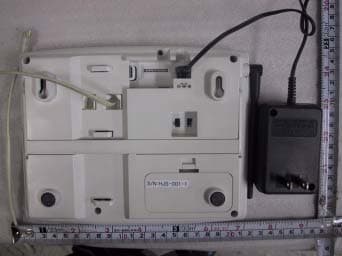
QUPSAVERCALL-3000
Feb 24, 2004Wireless Security System - Main Unit
Equipment Class
DSR - Part 15 Remote Control/Security Device Transceiver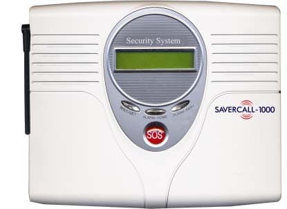
QUPSAVERCALL-1000
Mar 04, 2003Wireless Security System - Main Unit
Equipment Class
DSC - Part 15 Security/Remote Control Transmitter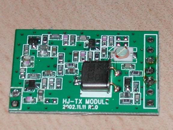
QUPHJ-MD100F
Mar 02, 2003Monitor Detector
Equipment Class
DSC - Part 15 Security/Remote Control Transmitter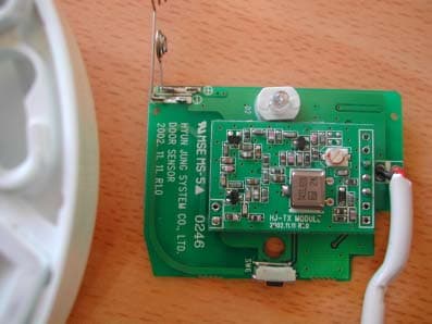
QUPHJ-FS100F
Mar 02, 2003Fire Sensor
Equipment Class
DSC - Part 15 Security/Remote Control Transmitter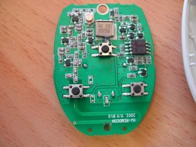
QUPHJ-RC100F
Feb 25, 2003Remote Controller
Equipment Class
DSC - Part 15 Security/Remote Control Transmitter