QVF0401BASE STATION
I-Tel Corporation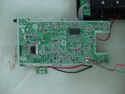
Click to zoom
Application Details
- Equipment Class
- DXT - Part 15 Low Power Transceiver, Rx Verified
- Date of Grant
- Jun 17, 2004
- Application Purpose
- Original Equipment
- Date of Application
- Jun 17, 2004
- Equipment Note
- BASE STATION
- Frequency Range
- 902.15000000 - 905.07500000
- Company
- I-Tel Corporation
- Country
- South Korea
Documents & Files
Document Text
Text extracted from the exhibit documents filed with the FCC. Open a document above to read the original.
Users Manual
5.8 GHz Cordless Telephone with Caller ID on Call Waiting 40 CHANNEL AUTOSCAN Model GH5816 OWNER S MANUAL INSTALLATION AND OPERATING INSTRUCTIONS PLEASE READ THIS MANUAL CAREFULLY BEFORE USE. KEEP FOR YOUR REFERENCE. For installation information, please see “Getting Started” instructions on page 5 or your separate Quick Start Guide. Visit Us on the Web: www .uselectronics.info © 2004 Bellsouth Corporation Congratulations on your selection of a qualityBellSouthproduct. With proper care, and by following the set-up and user instructions in this Owner’s Manual, this unit will provide you with years of trouble-free service. BellSouthis committed to providing quality products that fit your needs. We would like to have any comments or suggestions you might have on this product. You may mail your comments to: U.S. Electronics 105 Madison Avenue New York, NY 10016 When examining your newBellSouthcordless telephone, you will find an array of special features including: C C O O R R D D L L E E S S S S T T E E L L E E P P H H O O N N E E F F E E A A T T U U R R E E S S Filtered Sound TM System- Gets considerably less noise than conventional cordless telephones because of a special circuit which delivers the clearest possible reception. 40 Channel Auto Scan- Press thebutton on theHANDSETto find and lock on to the clearest channel for any call. Desk or Wall Mount -Use this equipment as a desk phone or as a wall phone. TONE or PULSE Dialing- Use this phone for either TONE (push-button) or PULSE (rotary) dialing. Automated Functions- Redial the last number called and automatic STANDBY mode. Security- Ensures greater privacy because a built-in security code with 65,536 combinations prevents use of your telephone line by another nearby cordless phone. Dependable Battery- Recharge your BATTERY PACK many times with the built-in charger. The battery low warning tone tells you when the BATTERY PACK needs recharging. (See page 29.) Special Services- Use thebutton to access special services such as Call Waiting supplied by your telephone company or company switchboard. STANDBY Mode- When in STANDBY mode (ON-HOOK), the phone is capable of receiving a call. When theHANDSETis on theBASE UNIT, it is automatically in the STANDBY mode (ON-HOOK). When theHANDSETis taken off theBASE UNIT, it remains in the STANDBY mode until you activate thebutton. Battery Power Saver- Once fully charged, in STANDBY mode, theHANDSETcan receive/send calls for a maximum of five days without the need for recharging. Length of charge depends on frequency of use. Luminous LCD Screen- The LCD Screen emits light for 5 seconds every time you press any of the buttons on theHANDSET. HANDSET Ringer Level- Select the ringer volume level (HI, LOW, OFF). HANDSET VOLUME CONTROL Switch- Select the receiver volume level (HI, MID, LOW). HEADSET JACK- Your telephone can utilize a headset for hands-free communication. BELT CLIP- Use the BELT CLIP to hang yourHANDSETon your belt. flash flash S S p p e e c c i i a a l l F F e e a a t t u u r r e e s s C C A A L L L L E E R R I I D D S S Y Y S S T T E E M M Multi-Function Large LCD Screen- Shows the number you are dialing, and with Caller ID service (available through subscription from your local telephone company), displays information about the caller before you answer the call. Name and Number PHONEBOOK- Stores up to 40 names and numbers so that you can call them with a single key stroke. Caller List- Available with Caller ID service. Stores up to 80 calls to keep track of everyone who called. The name, phone number, time, and date of the call are recorded.Allows you to return their calls with a single key stroke. Preferred Calls- You can mark the name and number of a welcome caller in the PHONEBOOK. When that number calls in, the caller’s name will appear on the LCD Screen and a special ring sound will be heard. Blocked Calls- You can mark the name and number of an unwelcome caller in the PHONEBOOK. When that number calls in, the caller’s name will appear on the LCD Screen and the ringer will be disabled. Repeat Call Indicator- Shows if a new incoming call has called more than once. Out of Area Call Indicator- Advises you that the incoming call is not in a Caller ID service area, or does not support the Caller ID system. Private Call Indicator- Advises you that the caller’s name and/or telephone number of the incoming call is blocked by the system. Call Waiting Service- Displays the name and number of the second caller, if you have subscribed to call waiting service from your local telephone company (See page 15). Voice Mail- Indicates message waiting signal if you subscribed to Voice Mail message service and requested Visual Message Indication from your local telephone company (see page 15). This telephone also detects a Stutter Dial Tone signal every time there is a Voice Mail message for your Voice Mail message provider if you have subscribed to Voice Mail message service. S S p p e e c c i i a a l l F F e e a a t t u u r r e e s s HANDSETControls 1.HANDSET ANTENNA 2.NEW CALL/MSG (MESSAGE) WAITING LED Indicator: Blinks when recording a new incoming call or when receiving a Message Waiting signal, if you have subscribed to a Voice Mail message service from your local telephone company. (See page 14 for details.) 3.LCD Screen: Shows call information, phone status, prompts, and PHONEBOOK items. 4.PHONE BOOKButton: Press to access names and numbers stored in the PHONEBOOK. (See pages 16 to 21 for details.) H H A A N N D D S S E E T T C C o o n n t t r r o o l l s s 2. NEW CALL/MESSAGE WAITING INDICATOR Pg. 14, 15 3. LCD SCREEN 1.HANDSETANTENNA 11. TALK BUTTON Pg. 6, 7, 11~13, 15~16, 20~21, 31 10. SCROLL UP-DOWN/ SHIFT LEFT-RIGHT BUTTON Pg. 14, 16~27 5. VOLUME CONTROL (HI, MID, LOW) SWITCH 7. DIAL 10 BUTTON Pg. 12, 16, 20~21, 25 8. DIAL 7/TEMPORARY TONE(*) BUTTON Pg. 12, 16, 18, 20~21, 25 6. REDIAL/SAVE/PAUSE BUTTON Pg. 13, 16~20, 23~26 17. EDIT BUTTON Pg. 16, 18~20, 23~27 4. PHONE BOOK BUTTON Pg. 16~21, …
Text truncated - open the document above for the full version.
Users Manual
19 E E d d i i t t i i n n g g a a N N a a m m e e a a n n d d N N u u m m b b e e r r i i n n t t h h e e P P H H O O N N E E B B O O O O K K 1. Press thebutton. The LCD Screen will display “DIRECTORY”. 2. Press the SCROLL UPor DOWNbutton to find the record you want to edit. 3. Press thebutton to edit the name, and the cursor will blink over the first character. 4. Press the SCROLL LEFTor RIGHTbutton to move the cursor to the letter or number you want to change. To erase, press thebutton. To add, use the TELEPHONE KEYPAD~buttons. (See page 27 for details.) 5. Press the SCROLL UPor DOWNbutton to edit the number. 6. Press the SCROLL LEFTor RIGHTbutton to move the cursor to the digit you want to change. To erase, press thebutton. To add, use the TELEPHONE KEYPAD ~buttons. (See page 27 for details.) 7. Press and hold down thebutton to confirm. IMPORTANT: It is not advisable to save a telephone number without the corresponding name in the PHONEBOOK. This will lead to improper displays on PRIVATE and OUT OF AREA calls. NOTE: When no active buttons are pressed for 20 seconds, the LCD Screen will automatically return to STANDBY mode. wxyz wxyz edit C C a a l l l l e e r r I I D D S S y y s s t t e e m m O O p p e e r r a a t t i i o o n n MICHAEL BROW 604-555-1212 # 8 TOTAL 12 DIR MICHAEL BROW 604 555 1212 # 8 TOTAL 12 DIR 6cursor is blinking MICHAEL BROW 604 555 1212 # 8 TOTAL 12 DIR cursor is blinking E E d d i i t t i i n n g g a a N N u u m m b b e e r r i i n n t t h h e e P P H H O O N N E E B B O O O O K K b b e e f f o o r r e e D D i i a a l l i i n n g g 1. Press thebutton. The LCD Screen will display “DIRECTORY”. 2. Press the SCROLL UPor DOWNbutton to find the caller. 3. Press thebutton to edit the name. 4. Press the SCROLL DOWNbutton. e.g.: 5. Press the SCROLL LEFTor RIGHTbutton to move the cursor to the number you want to change. To erase, press thebutton. To add, use the TELEPHONE KEYPAD~buttons. 6. Press and hold down the DIAL 7button for a local call, or press and hold down the DIAL 10button for a local call with area code, or press and hold down the DIAL 1+button for a long distance call. 7. To end your conversation, either press thebutton or place theHANDSETon the BASE UNIT. NOTE: If you want to save the edited number in the PHONEBOOK, follow steps 1 through 5 and then press and hold down thebutton. talk wxyz edit 20 MICHAEL BROW 604 555 1212 # 1 TOTAL 12 DIR 6cursor is blinking C C a a l l l l e e r r I I D D S S y y s s t t e e m m O O p p e e r r a a t t i i o o n n 21 P P l l a a c c i i n n g g C C a a l l l l s s f f r r o o m m t t h h e e P P H H O O N N E E B B O O O O K K 1. Press thebutton. The LCD Screen will display “DIRECTORY”. 2. Press the SCROLL UPor DOWNbutton to find the record you want to call. 3. Press and hold down the DIAL 7button for a local call, or press and hold down the DIAL 10button for a local call with area code, or press and hold down the DIAL 1+button for a long distance call. 4. To end the call, either press thebutton or place theHANDSETon theBASE UNIT. D D e e l l e e t t i i n n g g A A l l l l R R e e c c o o r r d d s s i i n n t t h h e e P P H H O O N N E E B B O O O O K K 1. Press thebutton. The LCD Screen will display “DIRECTORY”. 2. Press and hold down thebutton for at least 3 seconds while in DIRECTORY mode. 3. Press thebutton to return to STANDBY mode. S S e e l l e e c c t t i i v v e e D D e e l l e e t t i i n n g g i i n n t t h h e e P P H H O O N N E E B B O O O O K K 1. Press thebutton. The LCD Screen will display “DIRECTORY”. 2. Press the SCROLL UPor DOWNbutton to find the record you want to delete. 3. Press and hold down thebutton for at least 3 seconds, then the LCD Screen will display the next record in the PHONEBOOK. 4. Press thebutton to return to STANDBY mode. talk C C a a l l l l e e r r I I D D S S y y s s t t e e m m O O p p e e r r a a t t i i o o n n ALLDELETE 10:00 AM 8/24 TOTAL 0 DELETE # 5 TOTAL 12 22 F F u u n n c c t t i i o o n n O O p p e e r r a a t t i i o o n n You can change the settings on theHANDSETthrough the functions menu. This unit contains the following special functions: A. LANGUAGEF. PBX NUMBER B. SILENT ON/OFFG. FLASH TIME C. TIME SETH. PAUSE TIME D. RINGER VOLUMEI. VOICE MAIL E. (LCD) CONTRASTJ. MSG WAITING With theHANDSETin STANDBY mode, press thebutton. Then press the corresponding TELEPHONE KEYPAD~button or the SCROLL UPor DOWNbutton to access the desired setting. wxyz C C a a l l l l e e r r I I D D S S y y s s t t e e m m O O p p e e r r a a t t i i o o n n ENGLISH # 1 TOTAL 10 KEYPADButton 1 SILENT OFF # 2 TOTAL 10 KEYPADButton TIME SET 10:00 AM 8/24 # 3 TOTAL 10 KEYPADButton RING: HI # 4 TOTAL 10 KEYPADButton CONTRAST 1 # 5 TOTAL 10 KEYPADButton PBX NO. OFF # 6 TOTAL 10 KEYPADButton FLASH TIME 600 # 7 TOTAL 10 KEYPADButton PAUSE TIME 4 # 8 TOTAL 10 KEYPADButton VOICE MAIL # 9 TOTAL 10 KEYPADButton wxyz MSG WAITING OFF # 10 TOTAL 10 KEYPADButton A A . . L L a a n n g g u u a a g g e e This telephone offers English, Spanish, and French languages for your convenience. 1. Press thebutton. 2. Press the TELEPHONE KEYPADbutton. 3. Press thebutton. 4. Press the SCROLL UPor DOWNbutton to select the language you desire. You can also set the language by pressing the followingTELEPHONE KEYPAD buttons; for English,for Spanish, orfor French. English is the preset language. 5. Press and hold down thebutton. 6. Press thebutton to return to STANDBY mode. B B . . F F I I R R S S T T R R I I N N G G / / S S i i l l e e n n t t O O n n o o r r O O f f f f This telephone will generate the first ring sound even in the BLOCKED CALL mode to indicate that you have an incoming call. To keep the ringer silent in BLOCKED CALL mode, you can turn off the first ring sound. 1. Press thebutton. 2. Press the TELEPHONE KEYPADbutton. 3. Press thebutton. 4. Press the SCROLL UPor DOWNbutton to select the SILENT ON/OFF setting. You can also press the TELEPHONE KEYPAD buttons;for ON orfor OFF. SILENT OFF is the preset mode. 5…
Text truncated - open the document above for the full version.
External Photos
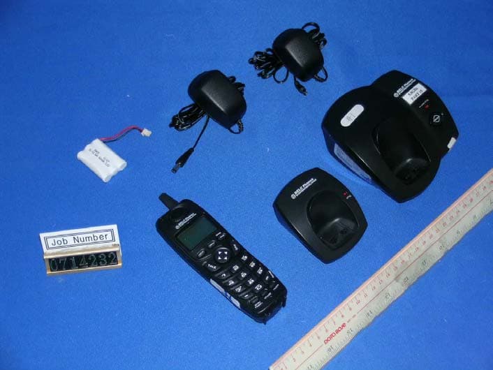
Photo of Product (GH5816) - Base Front - Base Back - Handset Front -Handset Back
ID Label/Location Info
LABEL Location GH5816X Model:GH5816XX FCCID:QVF0402
Internal Photos
- Base inside 1 - Base inside 2 - Handset inside
Internal Photos
Base Internal Photo Main controller Front Main controller Rear RF Module Front RF Module Rear
Operational Description
2 / 13 2. CIRCUIT DESCRIPTION A. BASE UNIT 1. TEL-LINE INTERFACE 2. RING DETECT 3. POWER SUPPLY 4. AUDIO AMPLIFIER AND COMPANDOR 5. DTMF GENERATOR 6. RSSI CONTROL 7. DATA COMMUNICATION INTERFACE 8. BASE RF MODULE B. PORTABLE UNIT 1. LOW BATTERY DETECTION CIRCUIT 2. BUZZER 3. INDICATOR CATEGORY 4. AUDIO AMPLIFIER AND COMPANDOR 5. PORTABLE RF MODULE 3 / 13 A. BASE SET 1. TEL-LINE INTERFACE TEL-LINE INTERFACE CIRCUIT CONSISTS OF SWITCH TRANSISTOR (Q7,Q11,Q9) DIODE BRIDGE (D6~D9), AND SPEECH NETWORK CIRCUIT AS FOLLOWS FIG.1 A DC LOOP IS CONFIGUED WHEN CPU PIN 23 ARE SET HI. THE LOOP CURRENT FLOWS AS FOLLOWS : TIP -> FUSE1 ->L1 ->D6 -> R13 -> Q11 -> D9 ->L2 RING THE PULSE SIGNAL FROM CPU PIN 23 ARE TRANSMITTED THROUGH LS1 TO TURN ON AND OFF THE TEL-LINE. FIG.1 2. RING DETECT 4 / 13 THE RING SIGNAL SUPPLIED BETWEEN T AND R PASSES THROUGH THE FOLLOWING PROCEDURES AND IS DETECTED BY THE CPU. TIP/RING Æ F1ÆL1/L2ÆR57/R56ÆC80/C44ÆOP AMP (IC3) CPU PIN 18 FIG.2 3. POWER SUPPLY 3-1 THE OUTPUT VOLTAGE OF U2 IS REGULATED 5V AND THIS VOLTAGE IS USED BY MAIN SUPPLYIING VOLTAGE OF CPU AND TX,RX POWER. FIG.3 Æ F1 BRIDGE OP AMP IC324 CPU RING DETECT T R AD APTOR ( 9V, 500m A) U3 REGULATOR UNREG VCC( 5V) U2 7805 ADAPTOR 9V300mA 5 / 13 4. AUDIO AMPLIFIER AND COMPANDOR 4-1 TX PART: THE TRANSMITTED SIGNALS FROM TELEPHONE LINE ARE FEED TO COMPANDOR IC(IC 4 ) THROUGH THE AUDIO AMPLIFIER AND THE RECEIVED SIGNALS FROM TELEPHONE LINE ARE ALSO FEED TO AUDIO AMPLIFIER THROUGH THE SPEECH NETWORK CIRCUIT. FIG.4 4-2 RX PART: THE RECEIVED SIGNALS FROM AF OUT OF RF MODULE, FEED TO COMPANDOR FOR NOISE ELIMINATION. THIS SIGNAL THROUGH MATCHING TRANS D6-D9, ALSO FEED TO TELEPHONE LINE THROUGH THE SPEECH NETWORK CIRCUIT TO. TRANSFER TO OTHER PARTY. FIG.5 RECTIFY D6-D9 SPEECH NETWORK CIRCUIT COMPANDOR IC RF, AF OUT TEL-LINE IC4 MUTE, CPU PIN 21 COMPANDOR IC RF, AF IN RECTIFY D6-D9 TEL-LINE SPEECH NETWORK IC4 CIRCUIT MUTE , CPU PIN 21 MUTE , CPU PIN 21 IC 4 6 / 13 5. DTMF GENARATOR THE DTMF GENERATOR IN CPU IS INTENDED TO PROVIDE DUAL-TONE MULTI- FREQUENCY (DTMF) FOR TONE DIALLING SYSTEM. FIG.6 6. RSSI CONTROL RSSI LEVEL OUTPUT FROM THE IF IC THROUGH Q13 OUT OF IS DETECTING BY PIN 13 OF CPU. FIG.7 CIRCUIT SPEECH NETWORK (IC1) TEL- LINE Q9 BU SYPI N 28 OF CPU CPU PIN 13 OF CPU Q13 7 / 13 7. DATA COMMUNICATION INTERFACE. * DATA COMMUNICATION IS OPERATED SERIAL OUTPUT 7-1 PIN 17(RX DATA) OF CPU : DATA SIGNAL WILL RECEIVE FROM THE PORTABLE UNIT AS THROUGH FILTER CIRCUIT Q13 AND DATA SIGNAL INPUT PIN 17 (RX DATA) OF CPU FIG.8 7-2 PIN 8 (TXDATA) OF CPU : DATA SIGNAL WILL SEND TO THE PORTABLE UNIT AS THROUGH PIN 8 (TX DATA) OF CPU FIG.9 8. PAGING FUNCTION PAGING FUNCTION CAN BE SELECTED EITHER FROM BASE TO PORTABLE UNIT. THE INTERCOM FUNCTION CAN BE ENABLED BY PRESSING THE PAGING KEY IN THE BASE SET. FIG.10 AF I NPI N 27 ( TX DATA) 27 AF - I N PIN KE Y CPU PIN PAGINGRF MODULE 6 FILTER CKT` AF OU T PI N 26 OF CPU IC2 Q13 PIN 17 OF CPU PIN 8 14 8 8 / 13 9. BASE RF MODULE 9-1. RX PART THE RECEIVER FRONT-END CONTAINS A BPF FILTER, AN RF LOW NOISE AMPLIFIER, A ACTIVE TRANSISTOR MIXER, A MONOLITHIC CRYSTAL FILTER AND 10.7MHz IF AMPLIFIER. ALSO IT INCLUDES BUFFER AMPLIFIERS FOR THE GENERATION OF LOCAL OSCILATOR POWER. THIS FRONT-END RECEIVER RECEIVES AN RF SIGNAL FROM THE ANTENNA. AND RF SIGNALS WITHIN THIS FREQUENCY RANGE IS 5727.625MHz~5732.500MHz PASS THROUGH RF AMP (Q306) AND BPF FILTER. AFTER PASSING THROUGH THE BPF FILTER, THE SIGNAL IS MIXED WITHIN 1'ST LOCAL FREQUENCY FROM VOLTAGE CONTROLLED OSCILLATOR. THE SIGNAL IS AMPLIFIED ON THE IF AMP TRANSISTOR (Q308,) AND THE SIGNAL PASS THROUGH THE CERAMIC FILTER (10.5MHz). AFTER THE IF SIGNAL PASS THE CERAMIC FILTER, THE SIGNAL ENTER BY THE FM IF (INTERMEDIATE FREQUENCY) I C. AND THE SIGNAL IS MIXED IN THE FM IF IC (KA3361). THE OUTPUT SIGNAL IN THE FM IF IC STREAMS FROM THE AF-OUT TEMINAL OF THE CONNECTOR 1 TO THE BASE. FIG.11 DBL5018AF-OUT TCXO 11.15MHz ANTENNA Q303 FREQ. IF IC MIXERVCO LNA LOCAL 10.5MHz GND GND BPF 302 650KHz CERAMIC FILTER LNA Q306 KA3361 9 / 13 9-2. TX PART THE SIGNAL IS MADE TO THE BASE, ENTER BY THE AF-IN TERMINAL OF THE CONNECTOR 1. THE SIGNAL SEND THE MOD TERMINAL OF THE TX VCO. THE SIGNAL IS MIXED IN THE TX VCO MIXING THE RF SIGNAL. THE RF SIGNAL ENTER BY THE TRANSMITION POWER AMP TRANSISTOR (Q303) ENTER BY THE BPF FILTER. THE RF SIGNAL PASS THROUGH THE BPF FILTER, TOWARDS THE ANT. THE LAST TRANSMITTION RF SIGNAL IS 902.150MHz∼905.075MHz FIG. 12 AF-IN VCO ANTE NNA BPF 301 PLL I C TRIMER VC301 Q301 I C301 RF MODULE Q303 10 / 13 B. PORTABLE UNIT 1. LOW BATTERY DETECTION CIRCUIT IC U1 IS CONTROLLED BY BATTERY VOLTAGE. IF THE VOLTAGE OF BATTERY PACK IS BELOW 3.3V, CHANGED FROM HIGH TO LOW AT PIN 70 OF CPU THEN CPU BECOMES TO RECOGNIZE TO LOW VOLTAGE OF BATTERY PACK FIG.13 2. BUZZER BUZZER IS CONTROLLED BY PIN 88,89 OF CPU DURING RECEIVED RING SIGNAL AND KEY INPUT FIG.14 3. INDICATOR CATEGORY ALL INDICATOR IS DISPLAYED AT LCD WINDOW BY THE CPU CONTROL 4. AUDIO AMPLIFIER AND COMPANDOR BATT Q1 , Q4 PIN5 OF CPU PI N22 OF CPU Q8 BUZZER U1 PIN 70 OF CPU PIN 88,89OF CPU Q5 , Q6 11 / 13 4-1 TX PART THE TRANSMITTED SIGNALS FROM MIC ARE FEED TO COMPANDOR IC1 THROUGH SIGNALS INPUT RF MODULE AF-IN FIG.15 4-2 RX PART THE RECEIVED SIGNALS FROM AF OUT CONTAIN SIGNALS AND PASS ONLY THROUGH COMPANDOR FOR NOISE ELIMINATION AND SIGNAL INPUT AUDIO AMPLIFIER. FIG.16 IC2- C PI N8 OF I C1 PI N34 OF I C4 ( CPU ) COMP- IN MIC AF IN (RF) MUTE FIL- OUT PI N1 OF I C1 AF OU T SVR2 EXP- IN PI N15 OF I C1 PI N19 OF I C1 EXP- OUT IC2- D, Q9 AUDIO AMP RECEIVER ( 50KB) COMP-IN PIN8 OF IC1 EXP – IN PIN 15 OF IC1 EXP – OUT PIN 19 OF IC1 Q2 AUDIO AMP 12 / 13 5. PORTABLE RF MODULE 5-1. RX PART THE RECEIVER FRONT-END CONTAINS A SAW DUPLEX FILTER, AND RF LOW NOISE AMPLIFIER, A ACTIVE TRANSISTOR MIXER, A CERAMIC FILTER AND 10.7MHz "IF" AMPLIFIER. ALSO IT INCLUDES BUFFER AMPLIFIERS OR THE GENERATION OF LOCAL OSCILATOR POWER. THIS FRONT-END RECEIVES AN RF SIGNAL FROM THE ANTENNA. AND RF SIGNALS WITHIN THIS FREQU…
Text truncated - open the document above for the full version.
Schematics
5816BM_CIR_040428_REV03.sch-1 - Mon May 10 17:47:36 2004 5816HM_CIR_040428_REV03.sch-1 - Mon May 10 17:48:50 2004 gh5816brf.sch-1 - Fri Mar 19 14:13:36 2004 gh5816prf.sch-1 - Fri Mar 19 14:14:53 2004
Test Report
KTL Korea Testing Laboratory Page 1 of 15 TEST REPORT Ref. Report No. 04-PIS03334-15-1 This test report only responds to the tested sample and shall not be reproduced except in full without written approval of the Korea Testing Laboratory. Tested and reported by Reviewed by Name and address of the applicant I-tel Corporation 5 th Fl., Sungwoo Bidg, 37-4 Haan-Dong, Kwangmyung-Si, Kyunggi-Do, Korea Standard / Test regulation FCC Part 15, Subpart C Test result Pass Incoming date : May 24, 2004 Test item(s) ; Low Power Transceiver, Rx Verified (900MHz/5.8GHz 40 Channel Analog Cordless Phone, Base Station) Model/type ref. ; GH5816 Manufacturer ; Bonso Electronics (Shenzhen) Co., Ltd. Additional information ; -Required Authorization : Certification -FCC ID. : QVF0401 Test date : May 24, 2004 – June 04, 2004 Issue date : June 07, 2004 Jeong-Min Kim, Senior Engineer Hee-Soo Kim , Telecommunication Team Manager KOREA TESTING LABORATORY FG101-01-02-00 222-13, Guro-Dong Guro-Gu Seoul Korea 152-053 http://www.ktl.re.kr Ref. Report No. 04 – PIS03334-15-1 Page 2 of 15 Korea Testing Laboratory Telecommunication Team 222-13, Guro3-dong, Guro-gu, Seoul Korea 152-848 TABLE OF CONTENTS I. GENERAL INFORMATION 3 1. Grantee’s Name and Mailing Address 2. Manufacturer's Name and Mailing Address 3. Equipment Descriptions 4. Rules and Regulations 5. Measuring Procedure 6. Place of Measurement 7. Date of Measurement II. GENERAL REQUIREMENTS OF THE EUT 4 1. Labeling Requirement (Section 15.19 and Section 15.214) 2. Information to User (Sections 15.21) 3. Special Accessories (Section 15.27) 4. Digital Security Code (Section 15.214) III. CONDUCTED EMISSION MEASUREMENT (Section 15.207) 5 1. Test Procedure 2. Photograph for the test configuration 3. Sample Calculation 4. Measurement Data IV. RADIATED EMISSION MEASUREMENT (Section 15.249) 9 1. Test Procedure 2. Photograph for the test configuration 3. Sample Calculation 4. Measurement Data V. OCCUPIED BANDWITH MEASUREMENT 14 VI. TEST EQUIPMENTS USED FOR FCC COMPLIANCE TESTING 15 Ref. Report No. 04 – PIS03334-15-1 Page 3 of 15 Korea Testing Laboratory Telecommunication Team 222-13, Guro3-dong, Guro-gu, Seoul Korea 152-848 I. GENERAL INFORMATION 1. Grantee’s Name and : I-tel Corporation Mailing Address 5 th Fl., Sungwoo Bidg, 37-4 Haan-Dong, Kwangmyung-Si,, Kyunggi-Do, Korea 2. Manufacturer's Name and : Bonso Electronics (Shenzhen) Co., Ltd. Mailing Address Da Yang Road, Da Yang Synthetical District, Fu Yong, Shenzhen, China 518103 3. Equipment Descriptions 3.1 Operating Frequency : 902.150 MHz ~ 905.075 MHz 3.2 Channel Space : 75 kHz 3.3 Power Supply : AC/DC Adapter (9.0V DC, 300mA) 3.4 Model Name : GH5816 * Multi-model name: The following model name is used in according to the color of cabinet and other marketing strategy but these items are identical in electrical, mechanical and physical design. GH5800XX, GH5815XX, GH5830XX, GH5801XX, GH5831XX, GH5802XX, GH5817XX, GH5832XX, GH5803XX, GH5818XX, GH5833XX, XG5104XX, XG5204XX, XG5404XX, XG5105XX, XG5205XX, XG5405XX, XG5106XX, XG5206XX, XG5406XX, XG5107XX, XG5207XX, XG5407XX, CTA-300, CTA-600, CTA-600M, CTA-700 4. Rules and Regulations : FCC Part 15, Subpart C 5. Measuring Procedure : ANSI C63.4-2001 6. Place of Measurement : Absorber-lined Room (KTL) 7. Date of Measurement 7.1 Conducted Emission : May 27, 2004 7.2 Radiated Emission : May 27, 2004 Ref. Report No. 04 – PIS03334-15-1 Page 4 of 15 Korea Testing Laboratory Telecommunication Team 222-13, Guro3-dong, Guro-gu, Seoul Korea 152-848 II. GENERAL REQUIREMENTS OF THE EUT 1. Labelling Requirement (Section 15.19 and Section 15.214) This device complies with Part 15 of the FCC Rules. Operation is subject to following two condition : (1) this device may not cause harmful interference, and (2) this device must accept any interference received, including interference that may cause undesired operation. Privacy of communication may not be ensured when using this phone. 1.1 Location on Label : User’s Manual 1.2 How Applied : Printed 2. Information to User (Section 15.21) The following or similar statements were provided in the manual for user instruction. Please refer page 33 of the attached manual for details. CAUTION : Any changes or modifications in construction of this device which are not expressly approved by the party responsible for compliance could void the user's authority to operate the equipment. 3. Special Accessories (Section 15.27) 3.1 Were the special Accessories provided? [ ] yes, [ x ] no 3.2 If yes, details for the special accessories are as follows : 3.3 If yes, were the appropriate instructions provided on the first page of the text concerned with the device? [ ] yes, [ ] no 3.4 Are these accessories provided of the type which can be readily obtained from multiple retail outlets ? [ ] yes, [ ] no And therefore does the manual specify what additional components or accessories are required to used in order to comply with the Rules? [ ] yes, [ ] no 4. Digital Security Code (Section 15.214) Was a circuitry for digital security code provided in the cordless telephone system ? [ x ] yes, [ ] no Ref. Report No. 04 – PIS03334-15-1 Page 5 of 15 Korea Testing Laboratory Telecommunication Team 222-13, Guro3-dong, Guro-gu, Seoul Korea 152-848 III . CONDUCTED EMISSION MEASUREMENT (Section 15.207) 1. Test Procedure The base station(EUT) is designed to transmit on one of 40 channels in the band 902.150 to 905.075 MHz. Therefore measurements were performed with the equipment operating on two frequencies, which were the top(CH40) and bottom(CH1) in the band, as per Section 15.31(m). Test mode was charging mode and transmitting mode. Conducted emission measurements on the EUT were performed by "AC Power Line Conducted Emissions Testing" procedure as per ANSI C63.4. The EUT was set up on a wooden table 0.8 meters height, 1.0 by 1.5 meters in size, placed in the shielded enclosed with a side of wall of which constituted a vertical conducting surface of 2.2 m X 3.1 m in size t…
Text truncated - open the document above for the full version.
Test Setup Photos
Ref. Report No. 04 – PIS03334-15-1 Page 6 of 14 Korea Testing Laboratory Telecommunication Team 222-13, Guro3-dong, Guro-gu, Seoul Korea 152-848 2. Photograph for the test configuration 3. Sample Calculation The emission level measured in decibels was shown in following sample calculation. For example : Measured Value at 7.165 MHz 32.3 dB㎶ @ Average mode + Cable Loss * 0.0 dB = Conducted Emission 32.3 dB㎶ * In case of RG214/ RF cable 15Ft, the loss is about 0.17dB at the frequency of 30 MHz which is negligible. Ref. Report No. 04 – PIS03334-15-1 Page 10 of 14 Korea Testing Laboratory Telecommunication Team 222-13, Guro3-dong, Guro-gu, Seoul Korea 152-848 2. Photograph of the test configuration 3. Sample Calculation The emission level measured in decibels above one microvolt (dB㎶) was converted into microvolt per meter (㎶/m) as shown in following sample calculation. For example : Measured Value at 902.150 MHz 49.4 dB㎶ + Antenna Factor 22.9 dB/m + Cable Loss 5.4 dB - Preamplifier 0.0 dB - Distance Correction Factor * 0.0 dB = Radiated Emission 77.7 dB㎶/m ( 7673.6㎶/m ) * Extrapolated from the measured distance to the specified distance by an inverse linear distance extrapolation.
Contact Information
Applicant
Ki Won Lee(President)
Test Firm
KOSTEC Co., Ltd.Cho Jae-Beom
Technical Specifications
| # | Rule Parts | Frequency Range | Power Output |
|---|---|---|---|
| 1 | 15C | 902.15 MHz - 905.075 MHz | - |
Other Applications from I-Tel Corporation
QVF0701H
Aug 07, 20075.8GHz/2.4GHz Analog Cordless Phone w/CID-Handset
Equipment Class
DXT - Part 15 Low Power Transceiver, Rx Verified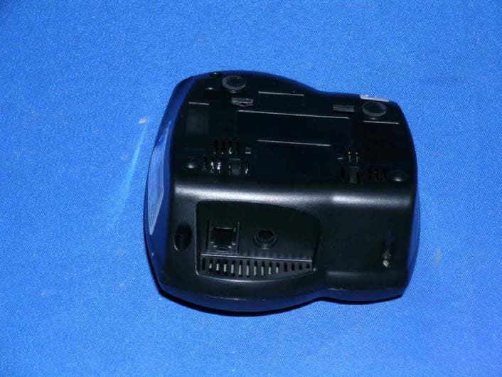
QVF0701
Aug 06, 20075.8GHz/2.4GHz Analog Cordless Phone w/CID - Base
Equipment Class
DXT - Part 15 Low Power Transceiver, Rx Verified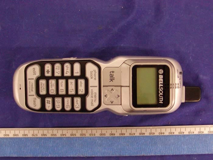
QVF0410
Nov 04, 20045.8 GHz FHSS Cordless Phone
Equipment Class
DSS - Part 15 Spread Spectrum Transmitter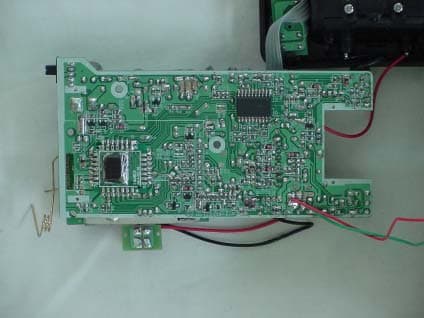
QVF0402
Jun 24, 2004900MHz / 5.8GHz CORDLESS PHONE HANDSET
Equipment Class
DXT - Part 15 Low Power Transceiver, Rx Verified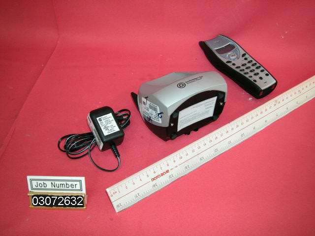
QVF0303
Sep 19, 20032.4GHz/5.8GHz 40 Channel Analog Cordless Phone
Equipment Class
DXT - Part 15 Low Power Transceiver, Rx Verified