QVF04105.8 GHz FHSS Cordless Phone
I-Tel Corporation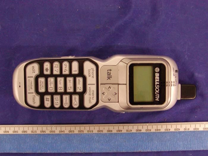
Click to zoom
Application Details
- Equipment Class
- DSS - Part 15 Spread Spectrum Transmitter
- Date of Grant
- Nov 04, 2004
- Application Purpose
- Original Equipment
- Date of Application
- Nov 04, 2004
- Equipment Note
- 5.8 GHz FHSS Cordless Phone
- Frequency Range
- 5761.48600000 - 5839.07700000
- Company
- I-Tel Corporation
- Country
- South Korea
Documents & Files
Document Text
Text extracted from the exhibit documents filed with the FCC. Open a document above to read the original.
Users Manual
Multi-HANDSET5.8 GHz Digital Frequency Hopping Spread Spectrum Technology CORDLESS ALLDIGITALANSWERING SYSTEM WITH CALLER ID / CALLWAITING 75 CHANNELAUTOHOP Model GH5862EX-3 OWNER’S MANUAL INSTALLATION AND OPERATING INSTRUCTIONS PLEASE READ THIS MANUALCAREFULLY BEFORE USE. KEEPFOR YOUR REFERENCE. For installation information, please see “Getting Started” instructions on page 6 or your separate Quick Start Guide. *This product combines 5.8 GHz and 900 MHz technology. Visit Us on the Web: www.uselectronics.info ©2004 BellSouth Corporation Congratulations on your selection of a quality BellSouthproduct. With proper care, and by following the set-up and user instructions in this Owner’s Manual, this unit will provide you with years of trouble-free service. BellSouthis committed to providing quality products that fit your needs. We would like to have any comments or suggestions you might have on this product. You may mail your comments to: U.S. Electronics 105 Madison Avenue New York, NY10016 When examining your new BellSouthcordless telephone, you will find an array of special features including: Digital Frequency hopping Spread Spectrum Technology- Utilizes a “Frequency hopping” for a more secure conversation with a clarity of digital sound, extended range, and minimal interference from other cordless telephones. 75 Channel Auto-hop- When interference is received, the telephone automatically hops to the clearest channel. Desk Mount - Use this equipment as a desk phone. TONE or PULSE Dialing- Use this phone for either TONE (push-button) or PULSE (rotary) dialing. Automated Functions- Redial the last number called. Security- Ensures greater privacy because of a built-in security code with 130,000 possible combinations that prevents use of your telephone line by another nearby cordless phone. Special Services- Use the button to access special services such as Call Waiting supplied by your telephone service provider or company switchboard. STANDBYMode- When in STANDBYmode (ON-HOOK), the phone is capable of receiving a call. When the HANDSETis on the BASE UNIT, it is automatically in the STANDBYmode (ON-HOOK). When the HANDSETis taken off the BASE UNIT, it remains in the STANDBY mode until you activate the button. Battery Power Saver- Recharge your BATTERYPACK many times with the built-in CHARGER. Once fully charged, in STANDBYmode, the HANDSETcan receive/send calls for a maximum of five days without the need for recharging. Length of charge depends on frequency of use. Luminous LCD Screen- The LCD Screen emits light for 5 seconds every time you press any of the TELEPHONE KEYPAD buttons. HANDSET Ringer Level- Select the ringer sound level (Hi, Medium, Low, Off). HANDSET VOLUME CONTROLSwitch- Select the receiver volume level (hi, mid, low). HANDSET Ring Melody- Select the desired ring melody from the 10 available melodies. HEADSET JACK- Your telephone can utilize a headset for hands-free communication. BELT CLIP- Use the BELTCLIPto hang your HANDSETon your belt. talk S S p p e e c c i i a a l l F F e e a a t t u u r r e e s s C C A A L L L L E E R R I I D D S S Y Y S S T T E E M M Multi-Function Large LCD Screen- Shows the number you are dialing, and with Caller ID service (available through subscription from your local telephone service provider), displays information about the caller before you answer the call. Name and Number PHONE BOOK- Stores up to 40 names and numbers so that you can call them with a single key stroke. Caller List- Available with Caller ID service. Stores up to 80 calls to keep track of everyone who called. The name, phone number, time, and date of the call are recorded. Allows you to return their calls with a single key stroke. Preferred Calls- You can mark the name and number of a welcome caller in the PHONE BOOK. When that number calls in, the caller’s name will appear on the LCD Screen and a special ring will sound or a selected PREFERRED RINGER MELODYwill be heard. Blocked Calls- You can mark the name and number of an unwelcome caller in the PHONE BOOK. When that number calls in, the caller’s name will appear on the LCD Screen and the ringer will be disabled. Repeat Call Indicator- Shows if a new incoming call has called more than once. Out of Area Call Indicator- Advises you that the incoming call is not in a Caller ID service area. Unavailable Call Indicator- Advises you that the origin of the incoming call does not support the Caller ID system. Call Waiting Service- Displays the name and number of the second caller, if you have subscribed to Call Waiting service from your local telephone company (See page 14). M M U U L L T T I I - - H H A A N N D D S S E E T T S S Y Y S S T T E E M M Multi-HANDSET- Registers a total of 4 HANDSETSinto the operating system. Intercom Call- AHANDSETcan make an INTERCOM call to the other HANDSETSin the system. Call Transfer- During a telephone conversation, the call can be transferred from one HANDSETto another HANDSET. Extension Phone Detection- When one HANDSETis connected to a BASE UNIT, the LCD Screen of the other HANDSETSthat are linked to the same BASE UNITwill display “Line in Use”. Conference- During a telephone conversation, conference allows three way conversation. S S P P E E A A K K E E R R P P H H O O N N E E F F E E A A T T U U R R E E S S Speakerphone- This telephone allows you to answer calls using the BASE UNIT speakerphone function. S S p p e e c c i i a a l l F F e e a a t t u u r r e e s s A A N N S S W W E E R R I I N N G G S S Y Y S S T T E E M M F F E E A A T T U U R R E E S S Fully Digital Answering System- Provides a full range of answering functions without using cassette tapes. Digital Memory- Allows recording of memos and messages. Two-DigitLED Message Display- Indicates the number of messages, indicates the status of the system. Ring-Detection Selectable- Choose the number of times the telephone rings before the system answers. Voice Day/Time Stamp- System tells the day and time of each received message or r…
Text truncated - open the document above for the full version.
Users Manual
6 C C o o n n n n e e c c t t i i n n g g Y Y o o u u r r P P h h o o n n e e This section is a reference guide to the basic functions and operations of your cordless telephone. For more detailed descriptions of the operations and features of this telephone, refer to the Contents on page 1. 1. Carefully remove your cordless telephone from its shipping carton. If there is any visible damage, do not attempt to operate this equipment. Return it to the place of purchase. 2. Check to be sure you have all items that come with this cordless telephone system. You should have four HANDSETS, BASE UNIT, four AC/DC ADAPTERS, three CHARGER UNITS, TELEPHONE LINE CORD, SHORTTELEPHONE LINE CORD, four BELTCLIPS, and an Owner’s Manual. 3. Insert the small plug on the end of the AC/DC ADAPTER(9V DC, 500 mA) into the POWER- IN CONNECTION JACK at the back of the BASE UNIT. 4. Plug the AC/DC ADAPTER into a 120V AC wall outlet. USE ONLYWITH CLASS 2 POWER SOURCE 9V DC, 500 mAfor the BASE UNIT. USE ONLYWITH CLASS 2 POWER SOURCE 9V DC, 100 mAfor the CHARGER. 5. Insert one plug of the TELEPHONE LINE CORD into the house telephone jack and the other end into the TELEPHONE LINE CONNECTION JACK at the back of the BASE UNIT. (If you have an older 4-prong telephone jack, you will need an RJ-11C telephone jack adapter. This adapter is available at the same place you purchased your telephone.) 6. We recommend not placing this unit next to appliances. Doing so may cause interference. G G e e t t t t i i n n g g S S t t a a r r t t e e d d ! TELEPHONE LINE CORD SHORT TELEPHONE LINE CORD BELT CLIP(4) AC ADAPTER (4) BATTERY PACK HANDSET (4) BASE UNIT CHARGER(3) R R e e m m o o t t e e O O p p e e r r a a t t i i o o n n t t h h r r o o u u g g h h a a T T o o n n e e T T e e l l e e p p h h o o n n e e You can use many Answering System features when you are away from home. To protect your privacy, most of the features can be used only after you enter the three-digit Remote Access Code. R R e e m m o o t t e e A A c c c c e e s s s s C C o o d d e e s s The Remote Access Codes are preset at the factory as below. You can use the preset codes or choose your own. PRIMARYMAILBOX:999 MAILBOX 1:555 MAILBOX 2:666 MAILBOX 3:777 MAILBOX 4:888 NOTE:After a power failure, the BASE UNITRemote Access Codes willreturn to the factory preset codes. C C h h a a n n g g i i n n g g o o f f t t h h e e R R e e m m o o t t e e A A c c c c e e s s s s C C o o d d e e s s All of the digits of the Remote Access Codes are a combination of the numbers 5, 6, 7, 8, 9, and 0. IMPORTANT:Digits 1, 2, 3, 4,and the sequence 000 cannot be used when changing the Remote Access Codes for any mailbox (including the PRIMARYMAILBOX). 1.Press a mailbox button for MAILBOX 1, 2, 3, or 4. For the PRIMARYMAILBOX, follow steps 2 through 6. 2.Press and hold down the button until you hear the announcement, “Please enter new password.” 3.Press and hold down the button. Release the button when you hear the desired first digit of the code. 4.Press and hold down the button. Release the button when you hear the desired second digit of the code. 5.Press and hold down the button. Release the button when you hear the desired third digit of the code. 6.Press the button, the 3-digits you have selected will be announced. 7.If your new Remote Access Code is the same as that of another mailbox, the Answering System will not record your password and will announce, “Please try again.” code min code 36 R R e e m m o o t t e e C C o o n n t t r r o o l l O O p p e e r r a a t t i i o o n n U U s s i i n n g g t t h h e e R R e e m m o o t t e e I I n n s s t t r r u u c c t t i i o o n n C C o o d d e e 1.Dial your telephone number. 2.Listen to or bypass the OGM in the PRIMARYMAILBOX by entering your Remote Access Code. 3.A“beep”will sound when your Remote Access Code is correctly accepted by your Answering System. 4.If the announcement does not stop, enter the Remote Access Code again. 5.The Answering System will request that you enter the Instruction Code or press “0”for help. A.If you do not know the Instruction Code, press the “0”button immediately. The Answering System will announce the Instruction Codes. Otherwise, if a command is not received by the Answering System within 10 seconds, it will signal 3 “beeps”and hang up. The following is the Remote Instruction Code Help Menu: Instruction Codes To playback announcement press “5.” To record memo press “6.”(Press “0”for PRIMARYMAILBOX, press “1”for MAILBOX 1, press “2”for MAILBOX 2, press “3”for MAILBOX 3, and press “4”for MAILBOX 4.) To record announcement press “7.” To turn answering machine OFF or ON press “8.” To change mailbox press “(star).” To playback message press “2.” While inmessage playback: To repeat message press “1.” To skip message press “3.” To stop press “4.” To erase message press “9.” B.Press the corresponding number of the Instruction Code you wish to activate. You do not have to listen to the entire Instruction Code Help Menu before giving a command. You may enter the desired Instruction Code Number at any given time. C.After accessing the Answering System, you must enter the next command within 10 seconds after the end of each operation. Otherwise, your Answering System will hang up the phone automatically. 37 R R e e m m o o t t e e C C o o n n t t r r o o l l O O p p e e r r a a t t i i o o n n S S p p e e a a k k e e r r p p h h o o n n e e O O p p e e r r a a t t i i o o n n This telephone allows you to answer calls using the BASE UNITspeakerphone function. 1.When the phone rings, press the button. 2.Start your conversation. 3.To end your conversation, press the button again. NOTE:Press the or button to adjust the BASE UNITspeaker volume to a comfortable listening level. The LED Message Display will display the selected volume level: “0”- Speaker off “1~8”- Volume from low to high S S e e c c u u r r i i t t y y S S y y s s t t e e m m Your cordless telephone uses a digital coding security system to prevent u…
Text truncated - open the document above for the full version.
Block Diagram
dsp_RF-blockdia.sch-1 - Mon Sep 20 14:45:29 2004 Regulator IC Battery 5.8 TX ANT. Regulator IC Voltage detector CLK.DATA.TX-EN 5.8G BPF RESET EN. TX-mod.RX-EN. SYN-OUT 5.8 RX ANT. Charger CKT TCCTRL.RXDATARSTN.RSSI 13.824Mhz LNA 5.8G BPF X-TAL DSPG 5.8G FHSS RF RX GAIN Key Metrix 123456 ABCDEF FGHI 789 1234567890 *0# LCD MODULE D S P G H A N D Y B L O C K D I A G R A M D E S I G N 5.Ghz Convertor DH58RFC05 PWR amp. XF5800PD- SF1339 2.4Ghz Digital FHSS RFICDH24RF17B M C U DHL36000 2.5V 3.3V 3.0V MH 3.6V 600 mA CHG MIC,RECEIVER EEPROM 64K LCD Driver IC KA0074 BUZZER Regulator IC ADAPTOR 5.8 TX ANT. CLK.DATA.TX-EN 5.8G BPF Regulator IC EN. TX-mod. KA7805 RX-EN. SYN-OUT 5.8 RX ANT. Charger CKT TCCTRL.RXDATARSTN.RSSI 13.824Mhz LNA 5.8G BPF X-TAL DSPG 5.8G FHSS RF RX GAIN Key Metrix 123456789*0# D S P G B A S E B L O C K D I A G R A M D E S I G N 5.Ghz Convertor DH58RFC05 PWR amp. XF5800PD- SF1339 2.4Ghz Digital FHSS RFICDH24RF17B M C U DHL36000 25V 33V 30V DC 9V500mA CHG MIC,SPEAKER EEPROM +FLASH RAM RELAY, ADC SPEECH NETWOK 5.Ghz Convertor DH58RFC05 PWR amp. XF5800PD- SF1339 2.4Ghz Digital FHSS RFICDH24RF17B M C U DHL36000 3.3V 3.3V 5.0V DC 9V 500 mA CHG MIC,SPEAKERRE EEPROM + FLASH TEL LINE INTER FACE 5862_blockdia_HM.sch-1 - Mon Sep 20 14:41:26 2004 CHARGER_blockdia.sch-1 - Mon Sep 20 14:43:15 2004 5862_blockdia_BM.sch-1 - Mon Sep 20 14:39:10 2004 5862_blockdia_BM.sch-2 - Mon Sep 20 14:39:56 2004 5862_blockdia_HM.sch-2 - Mon Sep 20 14:42:07 2004
External Photos
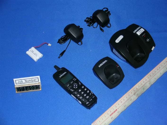
EXHIBIT C - EUT EXTERNAL PHOTOGRAPHS Base - Top View Base - Bottom View Handset – Top View Handset - Bottom View Power Adapter View
ID Label/Location Info
EXHIBIT A - FCC ID LABEL INFORMATION Proposed FCC ID Label Specifications : Text is black or white in color and is left justified. Labels are silk- screened and shall be “permanently affixed” at a conspicuous location on the EUT. Proposed Label Location on EUT Bottom Side of EUT/FCC ID Label FCC ID: I38-NA8300-001 This device complies with Part 15 of the FCC Rules. Operation is subject to the following two conditions: (1) this device may not cause harmful interference, and (2) this device must accept any interference received, including interference that may cause undesired operation. 2.1875" 1.0" FCC ID: QVF0410
Internal Photos
EXHIBIT C - EUT INTERNAL PHOTOGRAPHS Base – Chassis Cover off View Base - Main Board Component View Base - Main Board Solder View Base - Transceiver Top View Base – Transceiver Component View Base – Transceiver Bottom View Base – Chassis Cover off View Base - Main Board Component View Base - Main Board Solder View Handset – Transceiver Top View Handset - Transceiver Component View Handset - Transceiver Bottom View
Operational Description
The technical Description of Gh5862 1. RF Module RX Part RX LNA (DH58RFC05) The received signal within the 5.725~5.850GHz ISM band is typically band pass filtered by an external wideband pre-selector filter before application to a 5.8GHz LNA. RX Down-Conversion Mixer (DH58RFC05) The output of the LNA is fed internally to the input of the receive down conversion mixer. The receive mixer is implemented as a simple double- balanced mixer, and also provides a single ended to differential conversion function. 1 st IF Amplifier and Mixer (DH24RF17). The 2.4GHz 1 st IF signal from the receive down conversion mixer inter chip band pass filter is applied to the RX input of the DH24RF17 2.4GHz Transceiver. An integrated LNA amplifies the 2.4GHz signal prior to application to the image reject down conversion mixer. TX Part TX IF Amplifier (DH24RF17) The DH24RF17 contains an integrated power amplifier capable of producing +20dBm output power. The P.A. is implemented as a two stage complementary overdriven amplifier, operating between class AB and Class C. TX Up Conversion Mixer (DH58RF05) The TX IF signal within the 2.40~2.483 GHZ band from the DH24RF17 is internally AC-coupled inside the DH58RFC05 and converted to a differential signal by means of a passive balance. The signal is buffered by a differential amplifier and then up converted to the 5.8GHz band by mixing with the 3.3GHz LO in a simple double balanced mixer. TX Power Amplifier (DH58RFC05) The FSK modulated transmit signal is buffered and amplified by the power amplifier to a nominal level of +10dBm at the output of the DH58RFC05. The P.A. is implemented as a two stage amplifier, operating in Class B. The output stage is internally matched to 50ohm. 2. The base Band Part of The Base Unit. Tel line Interface. Separate then incoming and outgoing audio signal and sidetone. Make the tel-line on-hook and off- hook Ring Detect and Branch Phone Detect Detects the ring signal from the tel-line in on-hook status and informs the CPU, and detects if the branch phone is in the off hook mode or on-hook mode and then informs to the CPU. Audio Path Switch Circuitry, This circuitry can set up the path to implement the functions of talking with the telephone line, inter-communication, 3 way conference between the two handsets and tel-line. This circuitry is controlled by the CPU. The CPU It is the central controller. It manages the all parts including the audio path switch circuitry to work properly and the communication with the handset through the RF link. The frequency of the clock is 13.824MHz. 3. The Base Band part of The Handset Unit. Key Board, The user interface. Power Control Circuitry. Switch on or off the power of TX part and RX part of the RF module. It is controlled by the CPU. Charge Circuit and Charge Detector, Charge the battery in the handset when the handset is in the base cradle and detect if the handset is charging or not, and then informs to the CPU. The CPU It is the central controller. It manages the all parts including the audio path switch circuitry to work properly and the communication with the handset through the RF link. The frequency of the clock is 13.824MHz. 4. The Antennas It is single pole type and soldered permanently on the RF module of both base and Handset The End.
Schematics
dsp_RF-0904.sch-1 - Mon Sep 13 10:10:32 2004 5862_DIG_BM_0904.sch-1 - Mon Sep 13 10:04:46 2004 5862_DIG_HM_0904.sch-1 - Mon Sep 13 10:07:41 2004 Lcd0702.sch-2 - Mon Sep 13 10:12:09 2004 CHARGER.sch-1 - Mon Sep 13 10:09:29 2004 5862_DIG_BM_0904.sch-2 - Mon Sep 13 10:05:30 2004 5862_DIG_HM_0904.sch-2 - Mon Sep 13 10:08:21 2004
Test Report
Note: This test report is specially limited to the above client company and product model only. It may not be duplicated without prior written consent of Bay Area Compliance Laboratory Corporation. This report must not be used by the client to claim product endorsement by NVLAP or any agency of the U.S. Government. FCC PART 15.247 EMI MEASUREMENT AND TEST REPORT For I-TEL CORPORATION 5 th Floor, Sung Woo Building, 37-4 Hann-Dong Kwangmyung-Si, Kyunggi-Do, South Korea FCC ID: QVF0410 This Report Concerns: Original Report Equipment Type: 5.8GHz FHSS Cordless Phone Test Engineer: Ming Jin Report No.: R0409213 Test Date: 2004-11-01 Reviewed By: Daniel Deng Prepared By: Bay Area Compliance Laboratory Corporation 230 Commercial Street Sunnyvale, CA 94085 Tel: (408) 732-9162 Fax: (408) 732-9164 I-TEL CORPORATION FCC ID: QVF0410 Report # R0409213Rpt.doc Page 2 of 50 FCC Part 15.247 Test Report TABLE OF CONTENTS GENERAL INFORMATION.......................................................................................................................................4 PRODUCT DESCRIPTION FOR EQUIPMENT UNDER TEST (EUT) ....................................................................................4 OBJECTIVE...................................................................................................................................................................4 RELATED SUBMITTAL(S)/GRANT(S).............................................................................................................................4 TEST METHODOLOGY..................................................................................................................................................4 TEST FACILITY.............................................................................................................................................................4 SYSTEM TEST CONFIGURATION ..........................................................................................................................6 JUSTIFICATION.............................................................................................................................................................6 EUT EXERCISE SOFTWARE..........................................................................................................................................6 SPECIAL ACCESSORIES.................................................................................................................................................6 SCHEMATICS / BLOCK DIAGRAM.................................................................................................................................6 EQUIPMENT MODIFICATIONS.......................................................................................................................................6 LOCAL SUPPORT EQUIPMENT LIST AND DETAILS........................................................................................................6 EXTERNAL I/O CABLING LIST AND DETAILS...............................................................................................................6 CONFIGURATION OF TEST SYSTEM..............................................................................................................................7 TEST SETUP BLOCK DIAGRAM.....................................................................................................................................7 SUMMARY OF TEST RESULTS FOR FCC PART 15............................................................................................8 ANTENNA REQUIREMENT ......................................................................................................................................9 §15.207(A) - CONDUCTED EMISSION...................................................................................................................10 MEASUREMENT UNCERTAINTY..................................................................................................................................10 TEST SETUP................................................................................................................................................................10 SPECTRUM ANALYZER SETUP....................................................................................................................................10 TEST EQUIPMENT LIST AND DETAILS.........................................................................................................................10 TEST PROCEDURE......................................................................................................................................................10 ENVIRONMENTAL CONDITIONS..................................................................................................................................11 SUMMARY OF TEST RESULTS.....................................................................................................................................11 CONDUCTED EMISSIONS TEST DATA.........................................................................................................................11 PLOT OF CONDUCTED EMISSIONS TEST DATA...........................................................................................................11 §15.205 & §15.209 - RADIATED EMISSION...........................................................................................................14 MEASUREMENT UNCERTAINTY..................................................................................................................................14 TEST SETUP................................................................................................................................................................14 SPECTRUM ANALYZER SETUP....................................................................................................................................14 TEST EQUIPMENT LIST AND DETAILS...................…
Text truncated - open the document above for the full version.
Test Setup Photos
EXHIBIT B - TEST SETUP PHOTOGRAPHS Conducted Emission - Front View Conducted Emission - Side View Base Radiated Emission - Front View Base Radiated Emission - Rear View Handset Radiated Emission - Front View Handset Radiated Emission - Rear View
Contact Information
Applicant
Ki Won Lee(President)
Test Firm
Bay Area Compliance LaboratoryJohn Chan
Technical Specifications
| # | Rule Parts | Frequency Range | Power Output |
|---|---|---|---|
| 2 | 15C | 5.76 GHz - 5.84 GHz | 8.51 mW |
Other Applications from I-Tel Corporation
QVF0701H
Aug 07, 20075.8GHz/2.4GHz Analog Cordless Phone w/CID-Handset
Equipment Class
DXT - Part 15 Low Power Transceiver, Rx Verified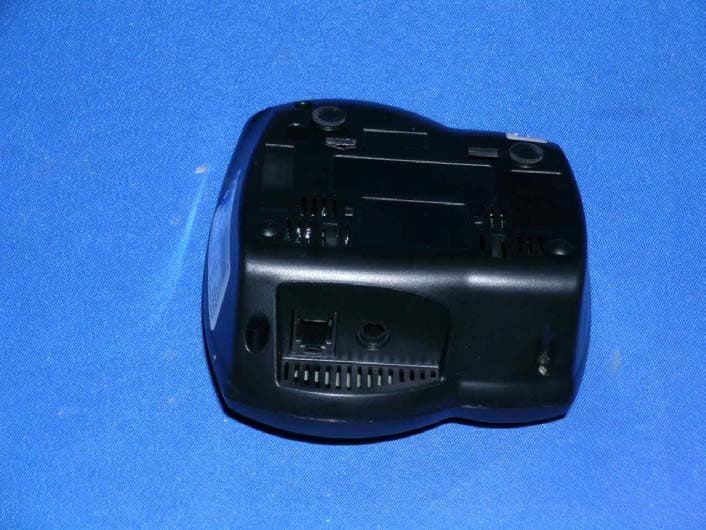
QVF0701
Aug 06, 20075.8GHz/2.4GHz Analog Cordless Phone w/CID - Base
Equipment Class
DXT - Part 15 Low Power Transceiver, Rx Verified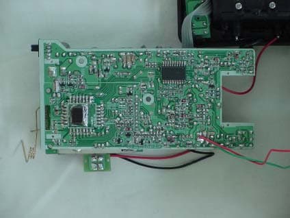
QVF0402
Jun 24, 2004900MHz / 5.8GHz CORDLESS PHONE HANDSET
Equipment Class
DXT - Part 15 Low Power Transceiver, Rx Verified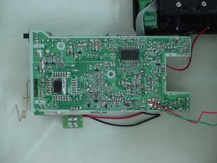
QVF0401
Jun 17, 2004BASE STATION
Equipment Class
DXT - Part 15 Low Power Transceiver, Rx Verified
QVF0303
Sep 19, 20032.4GHz/5.8GHz 40 Channel Analog Cordless Phone
Equipment Class
DXT - Part 15 Low Power Transceiver, Rx Verified