QWP5X250Wireless Ethernet Bridge
Cambium Networks Limited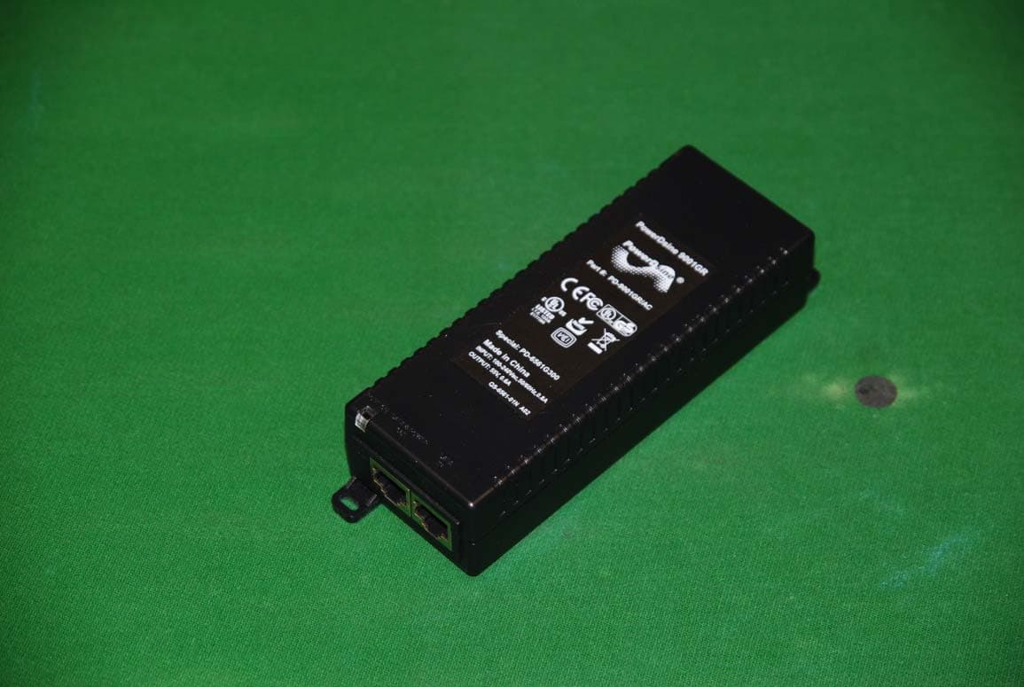
Click to zoom
Application Details
- Equipment Class
- DTS - Digital Transmission System
- Date of Grant
- Feb 01, 2012
- Application Purpose
- Original Equipment
- Date of Application
- Oct 11, 2011
- Equipment Note
- Wireless Ethernet Bridge
- Frequency Range
- 5755.00000000 - 5795.00000000
- Company
- Cambium Networks Limited
- Country
- United Kingdom
Documents & Files
Document Text
Text extracted from the exhibit documents filed with the FCC. Open a document above to read the original.
Users Manual
Motorola B2B Collateral Branding UK Manual Cover insert A4 Text Field Template (02/10/07) Sign o ........................................ date ................ Sht no 1 of 1 ag-UK-Manual Cover insert A4 Text Fields Template-00001-v02-ai-sw Customer Documetation UK 2007 PTP 250 phn-2182_003v004 User Guide System Release 250-02-00 Using this template follow these procedures. 1. Complete all the text fields using provided spreadsheet and specification information 2. Save file using appropriate naming title/convention in PDF format 2008 - 2010 Motorola, Inc. All Rights Reserved. © 2011 Motorola Solutions, Inc. All Rights Reserved. UNDER DEVELOPMENT phn-2182_003v004 (Oct 2011) Accuracy While reasonable efforts have been made to assure the accuracy of this document, Motorola Solutions, Inc. assumes no liability resulting from any inaccuracies or omissions in this document, or from use of the information obtained herein. Motorola Solutions, Inc. reserves the right to make changes to any products described herein to improve reliability, function, or design, and reserves the right to revise this document and to make changes from time to time in content hereof with no obligation to notify any person of revisions or changes. Motorola Solutions, Inc. does not assume any liability arising out of the application or use of any product, software, or circuit described herein; neither does it convey license under its patent rights or the rights of others. It is possible that this publication may contain references to, or information about Motorola products (machines and programs), programming, or services that are not announced in your country. Such references or information must not be construed to mean that Motorola intends to announce such Motorola products, programming, or services in your country. Copyrights This document, Motorola products, and 3 rd Party Software products described in this document may include or describe copyrighted Motorola and other 3 rd Party supplied computer programs stored in semiconductor memories or other media. Laws in the United States and other countries preserve for Motorola, its licensors, and other 3 rd Party supplied software certain exclusive rights for copyrighted material, including the exclusive right to copy, reproduce in any form, distribute and make derivative works of the copyrighted material. Accordingly, any copyrighted material of Motorola, its licensors, or the 3 rd Party software supplied material contained in the Motorola products described in this document may not be copied, reproduced, reverse engineered, distributed, merged or modified in any manner without the express written permission of Motorola. Furthermore, the purchase of Motorola products shall not be deemed to grant either directly or by implication, estoppel, or otherwise, any license under the copyrights, patents or patent applications of Motorola or other 3rd Party supplied software, except for the normal non-exclusive, royalty free license to use that arises by operation of law in the sale of a product. Restrictions Software and documentation are copyrighted materials. Making unauthorized copies is prohibited by law. No part of the software or documentation may be reproduced, transmitted, transcribed, stored in a retrieval system, or translated into any language or computer language, in any form or by any means, without prior written permission of Motorola Solutions, Inc. License Agreements The software described in this document is the property of Motorola Solutions, Inc. and its licensors. It is furnished by express license agreement only and may be used only in accordance with the terms of such an agreement. High Risk Materials Components, units, or 3 rd Party products used in the product described herein are NOT fault-tolerant and are NOT designed, manufactured, or intended for use as on-line control equipment in the following hazardous environments requiring fail-safe controls: the operation of Nuclear Facilities, Aircraft Navigation or Aircraft Communication Systems, Air Traffic Control, Life Support, or Weapons Systems (High Risk Activities). Motorola and its supplier(s) specifically disclaim any expressed or implied warranty of fitness for such High Risk Activities. Trademarks MOTOROLA and the Stylized M Logo are registered in the US Patent & Trademark Office. All other product or service names are the property of their respective owners. PTP 250 User Guide phn-2182_003v004 (Oct 2011) UNDER DEVELOPMENT I Safety and regulatory information This section describes important safety and regulatory guidelines that must be observed by personnel installing or operating PTP 250 equipment. Important safety information To prevent loss of life or physical injury, observe the safety guidelines in this section. Power lines Exercise extreme care when installing antennas near power lines. Working at heights Exercise extreme care when working at heights. Grounding and protective earth The Outdoor Unit (ODU) must be properly grounded to protect against lightning. It is the user’s responsibility to install the equipment in accordance with national regulations. In the USA, follow Section 810 of the National Electric Code, ANSI/NFPA No.70-1984 (USA). In Canada, follow Section 54 of the Canadian Electrical Code. These codes describe correct installation procedures for grounding the outdoor unit, mast, lead-in wire and discharge unit, size of grounding conductors and connection requirements for grounding electrodes. Other regulations may apply in different countries and therefore it is recommended that installation of the outdoor unit be contracted to a professional installer. Using the correct power supply Always use the Motorola Power over Ethernet injector unit (PoE power supply) or Powered Indoor Unit (PIDU Plus) to power the ODU. Failure to use the correct power supply could result in equipment damage and will invalidate the safety certification and may cause a safety hazard. Safety and regulator…
Text truncated - open the document above for the full version.
Cover Letter(s)
POINT TO POINT WIRELESS SOLUTIONS GROUP Technical Report PTP250 Regulatory Software Summary supporting the FCC approval phn-2423 001V002 John Sharman Abstract This document demonstrates the methods used by Motorola Solutions to ensure that operation of the PTP5X250 product in the field guaranteed to conform to FCC regulations and how unauthorised software upgrades are prevented. Technical Report Confidential Page 1 of 11 PTP250 Regulatory Software Summary phn-2423 001V002 Technical Report Confidential Page 2 of 11 PTP250 Regulatory Software Summary phn-2423 001V002 Version details Version Date Change Author 001V002 2 October 2011 Removed reference to QWP58250 from Appendix Clem Fisher 001V001 12 October 2011 Modified Document to refer to software controls rather than an FCC Class II change. Makes document more generic Clem Fisher 001v000 26 Sept 2011 Issued version John Sharman 000v002 19 Sept 2011 Various changes after initial review John Sharman 000v001 8 Sept 2011 Initial John Sharman Technical Report Confidential Page 3 of 11 PTP250 Regulatory Software Summary phn-2423 001V002 Table of Contents 1. Introduction ................................................................................................................................ 4 2. References ................................................................................................................................. 4 3. Background ................................................................................................................................ 4 Appendix A - Software Security Description Guide ........................................................................... 6 A.1 Description Software ......................................................................................................................... 6 A.1.1 General software operation description ......................................................................................... 6 A.1.2 Radio frequency parameters modified by the software without any hardware changes. .............. 6 A.1.3 High level (simplified) block diagram of the software architecture. ................................................ 7 A.2 Labelling ............................................................................................................................................ 8 A.2.1 How will the device be labelled? .................................................................................................... 8 A.2.2 Verifying the correct version of software is running ....................................................................... 8 A.2.3 Software Version numbering system. ............................................................................................ 8 A.3 Security ............................................................................................................................................. 9 A.3.1 Third party operation ...................................................................................................................... 9 A.3.2 Third party capability ...................................................................................................................... 9 A.3.3 Software updates ......................................................................................................................... 10 A.3.4 Modification by third parties ......................................................................................................... 10 A.3.5 Non US software version ............................................................................................................. 10 A.3.6 Factory level changes .................................................................................................................. 10 A.4 Unauthorised software changes ..................................................................................................... 11 A.4.1 Open source software .................................................................................................................. 11 Technical Report Confidential Page 4 of 11 PTP250 Regulatory Software Summary phn-2423 001V002 1. Introduction Motorola is releasing a product which will operate in the 5.8GHz band under FCC Part 15C and in the 5.4GHz band under FCC Part 15E. This product will be known as the PTP5X250 and when made available for sale in the USA must only be capable of operation in accordance with FCC rules. Motorola identifies in this document the controls in place to ensure that only software released by Motorola can be used on this product and therefore how it will ensure continuing compliance with FCC rules in the event of future changes. 2. References International standards [1] FCC Part 15 Subpart E UNII Devices (15.401 ff) [2] Not used National standards [3] FCC KDB 594280, “Restrictions on Software Configuration for devices not approved as Software Defined Radios” V 01: 6/8/2011 [4] FCC KDB 442812, “Software Defined Radio Application Guide” V02: 2/24/2011 [5] FCC KDB178919, “Permissive Change Policies” V 05: 6/8/2011 [6] FCC KDB634817 “Frequency Range Listings for Certification Grants” V 02: 5/20/2011 Motorola documents [7] Phn 2418, PTP250 Operational Description 3. Background The FCC guidance KDB 594280 opens up the possibility for a manufacturer to add functionality to an approved product on non-SDR approvals. This KDB states - “The commission may allow grantees to permit specific parties, such as operating system providers, service providers or parties under the direct control of the grantee to enable software upgrades for field deployed non-SDR devices if the details of such arrangements are provided in a Class II permissive change filing made directly with the Commission.” Based on this, Motorola wishes to identify by the original submission and not by a Class II change the methods that would be used to comply with FCC guidelines in the KDB in the event of future changes. The Motorola…
Text truncated - open the document above for the full version.
External Photos
External Photographs of PTP5X250 Section 1: AC Power Supply Options Figure 1 – WB4105 ac PSU Figure 2 – WB4155 ac PSU Figure 3 – WB2521 PIDU Plus ac PSU Section 2: Outdoor Unit Photographs Figure 4 : Front view of integrated antenna version with antenna unattached. Figure 5: Front view of Connectorised version. Figure 6: Rear view of PTP5X250, showing label position
ID Label/Location Info
Appendix B - Labels a)Labels to be used on the PTP5X250 dual band product WB 4200 Product label – Integrated Antenna PTP5X250 North America region WB4201 Product label – Connectorised PTP5X250 North America region Technical Report ConfidentialPage 14 of 15 PTP250 Operational Description phn-2418 001v001
ID Label/Location Info
Exhibit Showing Position of Qualification Label
Internal Photos
Report No.: 052615-01 SPORTON International Inc. PAGE NUMBER : A1 OF A13 TEL : 886-2-2696-2468 ISSUED DATE : Feb. 24, 2011 FAX : 886-2-2696-2255 Photographs of EUT Report No.: 052615-01 SPORTON International Inc. PAGE NUMBER : A2 OF A13 TEL : 886-2-2696-2468 ISSUED DATE : Feb. 24, 2011 FAX : 886-2-2696-2255 Report No.: 052615-01 SPORTON International Inc. PAGE NUMBER : A3 OF A13 TEL : 886-2-2696-2468 ISSUED DATE : Feb. 24, 2011 FAX : 886-2-2696-2255 Report No.: 052615-01 SPORTON International Inc. PAGE NUMBER : A4 OF A13 TEL : 886-2-2696-2468 ISSUED DATE : Feb. 24, 2011 FAX : 886-2-2696-2255 Report No.: 052615-01 SPORTON International Inc. PAGE NUMBER : A5 OF A13 TEL : 886-2-2696-2468 ISSUED DATE : Feb. 24, 2011 FAX : 886-2-2696-2255 Report No.: 052615-01 SPORTON International Inc. PAGE NUMBER : A6 OF A13 TEL : 886-2-2696-2468 ISSUED DATE : Feb. 24, 2011 FAX : 886-2-2696-2255 Report No.: 052615-01 SPORTON International Inc. PAGE NUMBER : A7 OF A13 TEL : 886-2-2696-2468 ISSUED DATE : Feb. 24, 2011 FAX : 886-2-2696-2255 Report No.: 052615-01 SPORTON International Inc. PAGE NUMBER : A8 OF A13 TEL : 886-2-2696-2468 ISSUED DATE : Feb. 24, 2011 FAX : 886-2-2696-2255 Report No.: 052615-01 SPORTON International Inc. PAGE NUMBER : A9 OF A13 TEL : 886-2-2696-2468 ISSUED DATE : Feb. 24, 2011 FAX : 886-2-2696-2255 Report No.: 052615-01 SPORTON International Inc. PAGE NUMBER : A10 OF A13 TEL : 886-2-2696-2468 ISSUED DATE : Feb. 24, 2011 FAX : 886-2-2696-2255 Report No.: 052615-01 SPORTON International Inc. PAGE NUMBER : A11 OF A13 TEL : 886-2-2696-2468 ISSUED DATE : Feb. 24, 2011 FAX : 886-2-2696-2255 Report No.: 052615-01 SPORTON International Inc. PAGE NUMBER : A12 OF A13 TEL : 886-2-2696-2468 ISSUED DATE : Feb. 24, 2011 FAX : 886-2-2696-2255 Report No.: 052615-01 SPORTON International Inc. PAGE NUMBER : A13 OF A13 TEL : 886-2-2696-2468 ISSUED DATE : Feb. 24, 2011 FAX : 886-2-2696-2255
RF Exposure Info
Analysis of operating and installation requirements to satisfy FCC and Canada Regulations for RF exposure compliance for the 5.4/5.8GHz PTP5X250 Products John Sharman/Clem Fisher Ref: phn-2382 000v002 Abstract This document analyses the operating and installation requirements to ensure limits for RF Exposure compliance are not exceeded by the 5.4/5.8GHz PTP58250 products with integrated antenna or external antennas. The guidelines in FCC Bulletin 65 are used for the analysis. . Copyright Information This document is the confidential property of Motorola, Inc. and without its prior written consent may not be copied or released to third parties. MOTOROLA, the stylized M Logo and all other trademarks indicated as such herein are trademarks of Motorola, Inc. ® Reg. U.S. Pat & Tm. Office. PTP XXX is a trademark of Motorola, Inc. All other product or service names are the property of their respective owners. © 2006 Motorola, Inc. All rights reserved. The parameters quoted in this document must be specifically confirmed in writing before they become applicable to any particular order or contract. The company reserves the right to make alterations or amendments to the detail specification at its discretion. The publication of information in this document does not imply freedom from patent or other rights of Motorola Point to Point Wireless Solutions Group or others. MOTOROLA IN CONFIDENCE Revision History Version Date Comments Author 000v001 27.7.2011 Initial Issue John Sharman 000V002 12.10.2011 Updated to include 5.8GHz operation Clem Fisher phn_2382 000V002 11/10/2011 Page 2 of 8 MOTOROLA IN CONFIDENCE OPERATIONAL PARAMETERS OF THE PTP5X250 PRODUCT 1 Scope The purpose of this brief working paper is to identify the RF power produced by the PTP5X250 equipments under various operating conditions in both the 5.4GHz and 5.8GHz bands. There are two versions of the product identical apart from whether an integrated flat plate antenna is fitted or a connector plate is fitted allowing the connection of a range of external antennas: North America region PTP250 Integrated Antenna version WB4200 North America region PTP250 Connectorised version WB4201 The mean conducted RF power plus the antenna gain used in specific installations identifies the effective power density (dBm/cm 2 ) that is to be compared against allowed limits for human exposure. 2 References [1] Evaluating Compliance with FCC Guidelines for Human Exposure to Radio frequency Electromagnetic Fields: OET Bulletin 65, Edition 97-01, August 1997 [2] Radio Frequency Exposure Compliance of Radiocommunication Apparatus: RSS 102 3 Background Reference [1] identifies how the radiated power density should be calculated for different distances from the antenna. The variables used are Radiated Power Density (S), conducted power (P), Antenna Gain (G) and distance (R). The formula given is S= (P * G)/ (4 * Pi * R 2 ) The limit allowed for S depends on whether the exposure risk is to a member of the public or not. The PTP5X250 products are approved by the FCC under the Part 15 rules which requires (for example, Part 15.407(f)) that all products meet the radio frequency radiation requirements for the “general population/uncontrolled environment” case. At the frequency of operation of these products, this requires that the value of S to be used is 1mW/cm 2 . It is clear from [1] that the power to be used should be the maximum transmitted power, subject to any allowance for source-based time-averaging. Notes a) the FCC require that the power density be calculated at a minimum distance of 20cm b) the value of P * G is the same as the transmitted EIRP. phn_2382 000V002 11/10/2011 Page 3 of 8 MOTOROLA IN CONFIDENCE 4 PTP250 Specific Issues 4.1 FCC Regulations The PTP5X250 is approved under a) FCC Part 15.407 for operation at 5.4GHz and this regulation limits the maximum EIRP to 30.0dBm in a any channel bandwidth, the product uses 20 and 40MHz. The PTP250 products ensure that this power cannot be exceeded. b) FCC Part 15.247 for operation at 5.8GHz and this regulation limits the conducted power to 30dBm. As this is a product for point to point, the product is allowed unlimited antenna gain in this band, but the approval of the product in this band limits the antenna gain to 37.6dBi less 1dB external feeder loss and 1dB internal cable loss (35.6dBi effective gain) 4.2 Dual Polarisation The PTP250 product WB4200 uses an integrated dual polarised antenna, with each polarisation connected to an identical transceiver circuit inside the unit. In order to comply with the FCC EIRP limits, the design of the products reduces by 3dB the conducted power and EIRP of each of the two individual polarisations. The PTP250 product WB4201 replaces the integrated antenna with a connector plate which feeds the H/ V radio frequency outputs either to an external dual polar antenna or two single polar antennas. The maximum antenna gain and minimum feeder losses are defined in the User Guide such that the total EIRP cannot exceed 30dBm at 5.4GHz when the conducted output power of the radio is adjusted by the professional installer as instructed. 4.3 Power Control The power levelling loops in the product measure the transmitted power on each polarisation at all times and limit each to the Maximum Transmit Power –3dB. The Maximum Transmit Power during the transmit period (total for both polarisations) for PTP5X250 equipments is set in production to not exceed 7dBm (5.4GHz operation) and to ensure that the Maximum EIRP requirement during the burst (30 dBm) is not exceeded when the product is used with the supplied integrated antenna (G = 23dBi less 1.5dBi internal cable losses). When operated at 5.8GHz, the peak conducted power of both antenna ports combined does not exceed 25.3dBm when measured over the transmit burst (see Sporton Report No: FR052615-01). The PTP250 equipments operate on a TDD basis using the same frequency for up/down link. The transmit duty cycle resulting from the TD…
Text truncated - open the document above for the full version.
Test Report
SPORTON International Inc. No. 52, Hwa Ya 1st Rd., Kwei-Shan Hsiang, TaoYuan Hsien, Taiwan, R.O.C. Ph: 886-3-327-3456 / FAX: 886-3-327-0973 / www.sporton.com.tw Report Format Version: 03 FCC RADIO TEST REPORT Applicant’s company Motorola Solutions, Inc. Applicant Address Unit A1 Linhay Business Park Eastern Road, Ashburton, Devon FCC ID QWP58250 Manufacturer’s company JOY TECHNOLOGY (SHENZHEN) CO., LTD. Manufacturer Address Building A, B, C, D, HengKeng Ind., Shangpai, Shangwu,Aiqun Rd., Shiyan Town,Shenzhen 518108 China Product Name PTP250 Point to Point Broadband Wireless System Brand Name Motorola Model Name WB3721/WB3723 Test Rule Part(s) 47 CFR FCC Part 15 Subpart C § 15.247 Test Freq. Range 5725 ~ 5850MHz Received Date Nov. 24, 2010 Final Test Date Mar. 29, 2011 Submission Type Original Equipment Multiple Listing Please refer to section 3.7 Statement This test report covers operation in the Band 5725MHz to 5850MHz using 802.11n and 802.11a modes. Operation in other bands is not supported in the device. The test result in this report refers exclusively to the presented test model / sample. Without written approval of SPORTON International Inc., the test report shall not be reproduced except in full. The measurements and test results shown in this test report were made in accordance with the procedures and found in compliance with the limit given in ANSI C63.4-2003 and 47 CFR FCC Part 15 Subpart C. The test equipment used to perform the test is calibrated and traceable to NML/ROC. Report No.: FR052615-01 Report Format Version: 03 Page No. : i of ii FCC ID: QWP58250 Issued Date : May 04, 2011 Table of Contents 1. CERTIFICATE OF COMPLIANCE ......................................................................................................................... 1 2. SUMMARY OF THE TEST RESULT .......................................................................................................................... 2 3. GENERAL INFORMATION .................................................................................................................................. 3 3.1. Product Details .................................................................................................................................................................................... 3 3.2. Accessories ......................................................................................................................................................................................... 5 3.3. Table for Filed Antenna....................................................................................................................................................................... 6 3.4. Table for Carrier Frequencies ............................................................................................................................................................. 7 3.5. Table for Test Modes ........................................................................................................................................................................... 7 3.6. Table for Testing Locations .................................................................................................................................................................. 8 3.7. Table for Multiple List........................................................................................................................................................................... 9 3.8. Table for Supporting Units ................................................................................................................................................................... 9 3.9. Table for Parameters of Test Software Setting ..................................................................................................................................... 9 3.10. Test Configurations ........................................................................................................................................................................... 11 4. TEST RESULT ................................................................................................................................................... 14 4.1. AC Power Line Conducted Emissions Measurement ......................................................................................................................... 14 4.2. Maximum Conducted peak Output Power Measurement ............................................................................................................... 20 4.3. Power Spectral Density Measurement .............................................................................................................................................. 31 4.4. 6dB Spectrum Bandwidth Measurement .......................................................................................................................................... 40 4.5. Radiated Emissions Measurement .................................................................................................................................................... 47 4.6. Band Edge Emissions Measurement ................................................................................................................................................. 75 4.7. Antenna Requirements ..................................................................................................................................................................... 82 5. LIST OF MEASURING EQUIPMENTS ................................................................................................................... 83 6. TEST LOCATION.............................................................................................................................................. 85 7. TAF CERTIFICATE OF ACCREDITATION ............................................................................................................. 8…
Text truncated - open the document above for the full version.
Test Report
SPORTON International Inc. No. 52, Hwa Ya 1st Rd., Kwei-Shan Hsiang, TaoYuan Hsien, Taiwan, R.O.C. Ph: 886-3-327-3456 / FAX: 886-3-327-0973 / www.sporton.com.tw Report Format Version: 02 FCC EMC TEST REPORT Applicant’s company Motorola Solutions, Inc. Applicant Address Unit A1 Linhay Business Park Eastern Road, Ashburton, Devon Manufacturer’s company JOY TECHNOLOGY (SHENZHEN) CO., LTD. Manufacturer Address Building A, B, C, D, HengKeng Ind., Shangpai, Shangwu,Aiqun Rd., Shiyan Town,Shenzhen 518108 China Product Name PTP250 Point to Point Broadband Wireless System Brand Name Motorola Model Name WB3721/WB3723 Test Standard 47 CFR FCC Part 15 Subpart B Classification of ITE Class B Received Date Nov. 24, 2010 Final Test Date Mar. 29, 2011 Submission Type Original Equipment Multiple Listing Please refer to section 3.7 Statement This test report covers operation in the Band 5725MHz to 5850MHz using 802.11n and 802.11a modes. Operation in other bands is not supported in the device. The test result in this report refers exclusively to the presented test model / sample. Without written approval of SPORTON International Inc., the test report shall not be reproduced except in full. The measurements and test results shown in this test report were made in accordance with the procedures and found in compliance with the limit given in ANSI C63.4-2003 and 47 CFR FCC Part 15 Subpart B. The test equipment used to perform the test is calibrated and traceable to NML/ROC. Report No.: FD052615-01 Report Format Version: 02 Page No. : i of ii Issued Date : Apr. 06, 2011 Table of Contents 1. CERTIFICATE OF COMPLIANCE ......................................................................................................................... 1 2. SUMMARY OF THE TEST RESULT .......................................................................................................................... 2 3. GENERAL INFORMATION .................................................................................................................................. 3 3.1. Product Details .................................................................................................................................................................................... 3 3.2. Accessories ......................................................................................................................................................................................... 5 3.3. Table for Filed Antenna....................................................................................................................................................................... 5 3.4. Table for Carrier Frequenciess ............................................................................................................................................................ 6 3.5. Table for Test Modes ........................................................................................................................................................................... 6 3.6. Table for Testing Locations .................................................................................................................................................................. 7 3.7. Table for Multiple Listing.......................................................................................…
Text truncated - open the document above for the full version.
Contact Information
Applicant
Dominic Holton(Mr)
Technical Contact
Motorola SolutionsJohn Sharman
[email protected]+44 1364 655577
Unit A1, Linhay Business Park · Ashburton, Devon · United Kingdom
Non-Technical Contact
Motorola SolutionsRobert Baker
[email protected]+44 1364 655536
Test Firm
Sporton International Inc.Alex Chen
Technical Specifications
| # | Rule Parts | Frequency Range | Power Output |
|---|---|---|---|
| 2 | 15C | 5.75 GHz - 5.79 GHz | 665.00 mW |
Other Applications from Cambium Networks Limited

QWP-60V3000
Nov 10, 202060 GHz Outdoor Wireless Gigabit Ethernet Bridge
Equipment Class
DXX - Part 15 Low Power Communication Device Transmitter
QWP-60V1000
Nov 10, 202060 GHz Outdoor Wireless Gigabit Ethernet Bridge
Equipment Class
DXX - Part 15 Low Power Communication Device Transmitter
QWP-60V5000
Nov 10, 202060 GHz Outdoor Wireless Gigabit Ethernet Bridge
Equipment Class
DXX - Part 15 Low Power Communication Device Transmitter
QWP-50450I
May 21, 2015Wireless Ethernet Bridge, Dual Channel OFDM MIMO Combination Access Point, Subscriber Station and Point to Point Equipment
Equipment Class
DTS - Digital Transmission System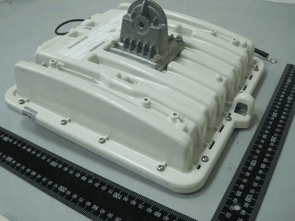
QWP58250
May 04, 2011PTP250 Point to Point Broadband Wireless System
Equipment Class
DTS - Digital Transmission System