QWU-03ATZ 150 Wireless / TZ 50 Wireless
Sonicwall, Inc.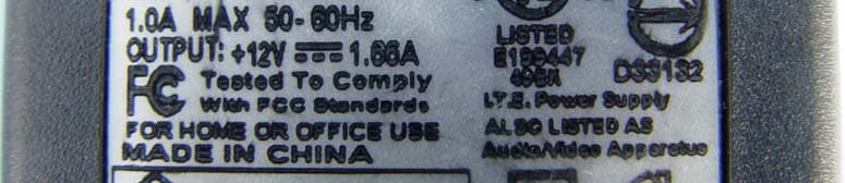
Click to zoom
Application Details
- Equipment Class
- DTS - Digital Transmission System
- Date of Grant
- Jan 18, 2005
- Application Purpose
- Original Equipment
- Date of Application
- Jan 18, 2005
- Equipment Note
- TZ 150 Wireless / TZ 50 Wireless
- Frequency Range
- 2412.00000000 - 2462.00000000
- Company
- Sonicwall, Inc.
- Country
- United States
Documents & Files
Document Text
Text extracted from the exhibit documents filed with the FCC. Open a document above to read the original.
Users Manual
SonicWALL TZ 150 WIRELESS Internet Security Appliance Regulatory Statement and Safety Instructions Regulatory Model/Type Product Name APL15-03A TZ 150 WIRELESS Class B Notice - Model APL15-03A FCC Part 15 Class B Notice NOTE: Models APL15-03A was tested and found to comply with the limits for a Class B digital device, pursuant to Part 15 of the FCC Rules. These limits are designed to provide reasonable protection against harmful interference in a residential installation. This equipment generates, uses, and can radiate radio frequency energy. And, if not installed and used in accordance with the instructions, may cause harmful interference to radio communications. However, there is no guarantee that interference will not occur in a particular installation. If the equipment does cause harmful interference to radio or television reception, which can be determined by turning the equipment off and on, the user is encouraged to try and correct the interference using one or more of the following measures: • Reorient or relocate the receiving antenna. • Increase the separation between the equipment and the receiver. • Connect the equipment into an outlet on a circuit different from the receiver connection. • Consult SonicWALL for assistance. Complies with EN55022 Class B and CISPR22 Class B. Refer to the label on the bottom of the unit for device information including Class A or Class B FCC information. Caution: Modifying this equipment or using this equipment for purposes not shown in this manual without the written consent of SonicWALL, Inc. could void the user’s authority to operate this equipment. This device complies with Part 15 of the FCC Rules. Operation is subject to the following two conditions: (1) This device may not cause harmful interference, and (2) this device must accept any interference received, including interference that may cause undesired operation. FCC RF Radiation Exposure Statement This equipment complies with FCC RF radiation exposure limits set forth for an uncontrolled environment. This equipment should be installed and operated with a minimum distance of 20 centimeters (7.9 inches) between the radiator (antenna) and your body. This transmitter must not be co-located or operating in conjunction with any other antenna or transmitter. For more information regarding the above statement, please contact SonicWALL, Inc. at 1143 Borregas Avenue, Sunnyvale, CA 94089-1306 or 1-408-745-9600. SonicWALL declares that the APL15-03A (FCC ID: QWU-03A) is limited in CH1~CH11 by specified firmware controlled in the USA Canada (IC): To prevent radio interference to the licensed service, this device is intended to be operated indoors and away from windows to provide maximum shielding. Equipment (or its transmit antenna) that is installed outdoors is subject to licensing. 1.Operation is subject to the following two conditions: 1) this device may not cause interference and 2) this device must accept any interference, including interference that may cause undesired operation of the device. This device has been designed to operate with an antenna having a maximum gain of 0 dBD. Antenna having a higher gain is strictly prohibited per regulations of Industry Canada. Therequired antenna impedance is 50 ohms." VCCI Statement Regulatory Information for Korea Ministry of Information and Telecommunication Certification Number All products are made in Taiwan R.O.C. All certificates held by NetSonic, Inc. Canadian Radio Frequency Emissions Statement This Class B digital apparatus complies with Canadian ICES-003. Cet appareil numérique de la classe B est conforme à toutes la norme NMB-003 du Canada. CISPR 22 (EN 55022) Class B Declaration of Conformity Application of council Directive 89/336/EEC (EMC) and 72/23/EEC (LVD) Standards to which conformity is declared EN55022 (1998) Class B EN 55024 (1998) A1 (2001) EN 61000-3-2 (2000) EN 61000-3-3 (1995) A1 (2001) EN 60950 (2000) National Deviations: AT, AU, BE, CH, CN, CZ, DE, DK, FI, FR, GB, GR, HU, IE, IL, IN, IT, JP, KR, NL, NO, PL, SE, SG, SI EN 50371 (2002) Directive 1999/5/EC (R&TTE) and standards EN 301 489-1/-17 and EN 300 328-1/-2 Cable Connections - All Models All Ethernet cables are designed for intra-building connection to other equipment. Do not connect these ports directly to communication wiring or other wiring that exits the building where the SonicWALL is located. Power Supply Information - All Models If the power supply is missing from your SonicWALL product package, please contact SonicWALL Technical Support at 408-752-7819 for a replacement. This product should only be used with a UL listed power supply marked “Class 2” or “LPS”, with an output rated 12 VDC, minimum 1.66 A. Wall Mounting the SonicWALL TZ 150 WIRELESS You can mount your SonicWALL TZ 150 WIRELESS on a wall or any vertical surface. Use the template on the next page as a guide for placing the mounting screws. 1. Using the template on the next page, attach two screws to the surface where you want to mount the security appliance. The mounting screws should have a head between 3/16” and 1/4” in diameter. The mounting screws should stick approximately 1/8” out from the surface. 2. Slide the slots in the back of the SonicWALL TZ 150 WIRELESS over the heads of the mounting screws and then slide the security appliance down to secure it in place. Considerations for Mounting all Models Mount in a location away from direct sunlight and sources of heat. A maximum ambient temperature of 104º F (40º C) is recommended. Route cables away from power lines, fluorescent lighting fixtures, and sources of noise such as radios, transmitters, and broadband amplifiers Ensure that no water or excessive moisture can enter the unit. Allow unrestricted airflow around the unit and through the vents on the side of the unit. A minimum of 1 inch (25.44mm) clearance is recommended. SonicWALL TZ 150 Wireless Getting Started Guide Page 1 SonicWALL TZ 150 Wireless Security Appliance Getting Started Guide…
Text truncated - open the document above for the full version.
Block Diagram
SerComm confidential Sercomm Confidential 7 III. BLOCK DIAGRAM System Bus Brecis CPU MSP2100 Switch HUB KS8995x LAN x 4 WAN LED 25MHz 25MHz Mini PCI for wireless access 4M FLASH 16M SDRAM 12V 0.8A DC input 5V 3.3V 2.5V 1.8V USB 2.0 Controller
Cover Letter(s)
1 steve.cheng 寄件者: [email protected] 寄件日期: 2005年1月17日星期一 下午 8:08 收件者: [email protected] 副本: [email protected] 主旨: Solve the comment for (Sonicwall FCC ID: QWU-03A) Dear Steve Question #1: P6 of test report stated two modes are identical, but internal photos shown different RF module was use in two models. Please clarify. Answer: 1. We only tested the mini PCI card which model is WL-850F, so remove the page 7 that Mini PCI card which model is XG-601 in the test report. 2. We also remove Mini PCI card which model is XG-601 in the external and internal photos. Please check Thanks for your asistance! Best Regards Wendy Liao Wendy Liao (廖意紋)/ ADT Corp. TEL: 03-318-3232 EXT 1625 FAX: 03-318-5050 Email: [email protected] 地址:桃園縣龜山鄉文化村華亞二路19號
Cover Letter(s)
steve.cheng 寄件者: steve.cheng [[email protected]] 寄件日期: 2005年1月14日星期五 上午 1:57 收件者: [email protected] 主旨: TCB Review Questions for (Sonicwall FCC ID: QWU-03A) 2005/1/19 TCB Review Questions for (Sonicwall FCC ID: QWU-03A) -EMC- Question #1: P6 of test report stated two modes are identical, but internal photos shown different RF module was use in two models. Please clarify. Best regards, Steve Cheng North American EMC Certification Services Inc. 359 Hawkland Cir., NW. Calgary, Alberta Canada T3G 3R3 Tel: (403) 241-8826 Email: [email protected] 2. The following product names are identical to each other except for their product name due to marketing requirement. Product Name Model No. TZ 150 WIRELESS APL15-03A TZ 50 WIRELESS APL15-03A
External Photos
Page 1 CONSTRUCTION PHOTOS OF EUT Page 2 Page 3 Page 4
ID Label/Location Info
FCC ID Label Location
Internal Photos
Page 5 Page 6 Page 7 Page 8 Page 9 Page 10 Page 11 Page 12
Operational Description
FCC ID: QWU-03A Report No.: RF931005L10 Operational Description This device is a Firewall/VPN Appliance with 802.11g Wireless Router (Product name: TZ 150 WIRELESS, TZ 50 WIRELESS) which operates in the 2.4GHz frequency spectrum with throughput of up to 54Mbps which OFDM technique will be applied. If the signal to noise radio is too poor which could not support 54Mbps, the 11Mbps data rate with CCK technique will be applied. The transmitter of the EUT is powered by AC adapter. The antenna is dipole antenna with UFL antenna. Under normal use condition, the user has to keep at least 20cm separation distance between radiator and the body of the user. The other instruction, please have a look at the users manual.
RF Exposure Info
FCC ID: QWU-03A Report No: SA931005L101 RF EXPOSURE REPORT REPORT NO. : SA931005L10 MODEL NO. : APL15-03A ACCORDING : FCC Guidelines for Human Exposure IEEE C95.1 APPLICANT : Sonicwall Inc. ADDRESS : 1143 Borregas Ave., Sunnyvale, CA 94089, U.S.A. ISSUED BY : Advance Data Technology Corporation LAB ADDRESS : No. 47, 14th Ling, Chia Pau Tsuen, Lin Kou Hsiang 244, Taipei Hsien, Taiwan, R.O.C. TEST LOCATION : No. 19, Hwa Ya 2nd Rd., Wen Hwa Tsuen, Kwei Shan Hsiang, Taoyuan Hsien 333, Taiwan, R.O.C. FCC ID: QWU-03A Report No: SA931005L102 RF Exposure Measurement (Mobile Device) 1. Introduction In this document, we try to prove the safety of radiation harmfulness to the human body for our product. The limit for Maximum Permissible Exposure (MPE) specified in FCC 1.1310 is followed. The Gain of the antenna used in this product is measured in a Fully Anechoic Chamber (FAC) calibrated for antenna measurement in ADT, and also the maximum total power input to the antenna is measured. Through the Friis transmission formula and the maximum gain of the antenna, we can calculate the distance, away from the product, where the limit of MPE is reached. Although the Friis transmission formula is a far field assumption, the calculated result of that is an over-prediction for near field power density. We will take that as the worst case to specify the safety range. 2. RF Exposure Limit According to FCC 1.1310: The criteria listed in the following table shall be used to evaluate the environmental impact of human exposure to radio-frequency (RF) radiation as specified in 1.1307(b) LIMITS FOR MAXIMUM PERMISSIBLE EXPOSURE (MPE) Frequency Range (MHz) Electric Field Strength (V/m) Magnetic Field Strength (A/m) Power Density (mW/cm 2 ) Average Time (minutes) (A)Limits For Occupational / Control Exposures 300-1500......F/3006 1500-100,000......56 (B)Limits For General Population / Uncontrolled Exposure 300-1500......F/15006 1500-100,000......1.030 F = Frequency in MHz FCC ID: QWU-03A Report No: SA931005L103 3. Friis Formula Friis transmission formula : Pd = (Pout*G) / (4*pi*r 2 ) where Pd = power density in mW/cm 2 Pout = output power to antenna in mW G = gain of antenna in linear scale Pi = 3.1416 R = distance between observation point and center of the radiator in cm If we know the maximum Gain of the antenna and the total power input to the antenna, through the calculation, we will know the MPE value at distance r. Ref. : David K. Cheng, Field and Wave Electromagnetics, Second Edition, Page 640, Eq. (11-133). 4 EUT Operating condition The software provided by Manufacturer enabled the EUT to transmit and receive data at lowest, middle and highest channel individually. 5. Classification The antenna of the product, under normal use condition, is at least 20cm away from the body of the user. Warming statement for keeping 20cm separation distance and the prohibition of operating next to a person has been printed on the user’s manual. So, this product is classified as the Mobile Device. FCC ID: QWU-03A Report No: SA931005L104 6 Test Results 6.1 Antenna Gain The maximum Gain measured in Fully Anechoic Chamber are 2dBi or 1.585 (numeric). 6.2 Output Power Into Antenna & RF Exposure value at distance 20cm: For DSSS Channel Channel Frequency (MHz) Output Power to Antenna (mW) Power Density (mW/cm 2 ) Limit of Power Density (mW/cm 2 ) 1241263.5330.0201.0 6243764.1210.0201.0 11246263.3870.0201.0 For OFDM Channel Channel Frequency (MHz) Output Power to Antenna (mW) Power Density (mW/cm 2 ) Limit of Power Density (mW/cm 2 ) 1241240.5510.0131.0 6243741.0200.0131.0 11246241.6870.0131.0
Schematics
SEP.08.2004 SEP.08.2004 SEP.08.2004
Test Report
FCC ID: QWU-03A Report No.: RF931005L101Report Format Version 2.0.1 FCC TEST REPORT REPORT NO. : RF931005L10 MODEL NO. : APL15-03A RECEIVED : Oct. 05, 2004 TESTED : Nov. 01 ~ Nov. 17, 2004 ISSUED : Jan. 05, 2005 APPLICANT : Sonicwall Inc. ADDRESS : 1143 Borregas Ave., Sunnyvale, CA 94089, U.S.A. ISSUED BY : Advance Data Technology Corporation LAB ADDRESS : No. 47, 14th Ling, Chia Pau Tsuen, Lin Kou Hsiang 244, Taipei Hsien, Taiwan, R.O.C. TEST LOCATION : No. 19, Hwa Ya 2nd Rd., Wen Hwa Tsuen, Kwei Shan Hsiang, Taoyuan Hsien 333, Taiwan, R.O.C. This test report consists of 72 pages in total. It may be duplicated completely for legal use with the approval of the applicant. It should not be reproduced except in full, without the written approval of our laboratory. The client should not use it to claim product endorsement by CNLA, A2LA or any government agencies. The test results in the report only apply to the tested sample. 0528 ILAC MR A No. 2177-01 FCC ID: QWU-03A Report No.: RF931005L102Report Format Version 2.0.1 Table of Contents 1CERTIFICATION ...................................................................................................4 2SUMMARY OF TEST RESULTS ...........................................................................5 2.1GENERAL DESCRIPTION OF EUT ......................................................................5 3GENERAL INFORMATION....................................................................................6 3.1GENERAL DESCRIPTION OF EUT ......................................................................6 3.2DESCRIPTION OF TEST MODES ........................................................................7 3.3GENERAL DESCRIPTION OF APPLIED STANDARDS .......................................7 3.4DESCRIPTION OF SUPPORT UNITS ..................................................................8 3.5CONFIGURATION OF SYSTEM UNDER TEST ...................................................9 4TEST TYPES AND RESULTS .............................................................................10 4.1CONDUCTED EMISSION MEASUREMENT ......................................................10 4.1.1LIMITS OF CONDUCTED EMISSION MEASUREMENT....................................10 4.1.2TEST INSTRUMENTS.........................................................................................10 4.1.3TEST PROCEDURES ......................................................................................... 11 4.1.4DEVIATION FROM TEST STANDARD ............................................................... 11 4.1.5TEST SETUP.......................................................................................................12 4.1.6EUT OPERATING CONDITIONS ........................................................................12 4.1.7TEST RESULTS ..................................................................................................13 4.2RADIATED EMISSION MEASUREMENT ...........................................................25 4.2.1LIMITS OF RADIATED EMISSION MEASUREMENT.........................................25 4.2.2TEST INSTRUMENTS.........................................................................................26 4.2.3TEST PROCEDURES .........................................................................................27 4.2.4DEVIATION FROM TEST STANDARD ...............................................................27 4.2.5TEST SETUP.......................................................................................................28 4.2.6EUT OPERATING CONDITIONS ........................................................................28 4.2.7TEST RESULTS ..................................................................................................29 4.2.8TEST RESULTS (A) ............................................................................................33 4.2.9TEST RESULTS (B) ............................................................................................36 4.36dB BANDWIDTH MEASUREMENT...................................................................39 4.3.1LIMITS OF 6dB BANDWIDTH MEASUREMENT ................................................39 4.3.2TEST INSTRUMENTS.........................................................................................39 4.3.3TEST PROCEDURE............................................................................................40 4.3.4DEVIATION FROM TEST STANDARD ...............................................................40 4.3.5TEST SETUP.......................................................................................................40 4.3.6EUT OPERATING CONDITIONS ........................................................................40 FCC ID: QWU-03A Report No.: RF931005L103Report Format Version 2.0.1 4.3.7TEST RESULTS (A) ............................................................................................41 4.3.8TEST RESULTS (B) ............................................................................................44 4.4MAXIMUM PEAK OUTPUT POWER ..................................................................47 4.4.1LIMITS OF MAXIMUM PEAK OUTPUT POWER MEASUREMENT ...................47 4.4.2TEST INSTRUMENTS ........................................................................................47 4.4.3TEST PROCEDURES .........................................................................................48 4.4.4DEVIATION FROM TEST STANDARD ...............................................................48 4.4.5TEST SETUP.......................................................................................................48 4.4.6EUT OPERATING CONDITIONS ........................................................................48 4.4.7TEST RESULTS (A) ............................................................................................49 4.4.8TEST RESULTS (B) ............................................................................................49 …
Text truncated - open the document above for the full version.
Test Setup Photos
FCC ID: QWU-03A Report No.: RF931005L1068Report Format Version 2.0.1 5 PHOTOGRAPHS OF THE TEST CONFIGURATION CONDUCTED EMISSION TEST (Adapter 1) FCC ID: QWU-03A Report No.: RF931005L1069Report Format Version 2.0.1 CONDUCTED EMISSION TEST (Adapter 2) FCC ID: QWU-03A Report No.: RF931005L1070Report Format Version 2.0.1 RADIATED EMISSION TEST (Adapter 1) FCC ID: QWU-03A Report No.: RF931005L1071Report Format Version 2.0.1 RADIATED EMISSION TEST (Adapter 2)
Contact Information
Applicant
Rick Linford(Regulatory Engineer)
Technical Contact
Advance Data Technology CorporationCody Chang
[email protected]886-3-3183232
No. 19, Hwa Ya 2nd Rd., Kwei Shan Hsiang · Taoyuan Hsien · Taiwan
Non-Technical Contact
Advance Data Technology CorporationStephanie Hung
[email protected]8863-3183232
Test Firm
Advance Data Tech. Corp. Hsin Chu EMCStephen Chen
Technical Specifications
| # | Rule Parts | Frequency Range | Power Output |
|---|---|---|---|
| 1 | 15C | 2.41 GHz - 2.46 GHz | 64.00 mW |
Other Applications from Sonicwall, Inc.

QWU-09E
Mar 06, 2012Wireless 802.11 abgn Device
Equipment Class
NII - Unlicensed National Information Infrastructure TX
QWU-09C
Feb 12, 2012Wireless 802.11bgn Access Point
Equipment Class
DTS - Digital Transmission System
QWU-08F
Oct 27, 2011Wireless 802.11 abgn Device
Equipment Class
NII - Unlicensed National Information Infrastructure TXQWU-091
Oct 27, 2011Wireless 802.11 abgn Device
Equipment Class
DTS - Digital Transmission System
QWU-081
Mar 02, 2011Access Point 802.11 a/b/g/n
Equipment Class
DTS - Digital Transmission System