QWV-M2MW2GSM/GPRS Wireless Modem
Bluetree Wireless Data Inc.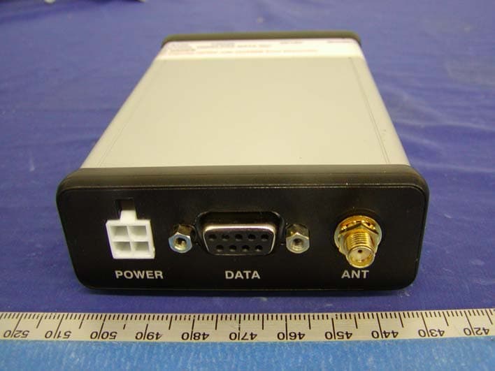
Click to zoom
Application Details
- Equipment Class
- PCB - PCS Licensed Transmitter
- Date of Grant
- Jul 15, 2004
- Application Purpose
- Original Equipment
- Date of Application
- Jul 15, 2004
- Equipment Note
- GSM/GPRS Wireless Modem
- Frequency Range
- 824.20000000 - 848.80000000
- Company
- Bluetree Wireless Data Inc.
- Country
- Canada
Documents & Files
Document Text
Text extracted from the exhibit documents filed with the FCC. Open a document above to read the original.
Users Manual
M2M Express GPRS Modem V1.5BlueTree Wireless M2M Express Product Manual3 BlueTree Wireless M2M ExpressGPRS Modem Model: M2M-GPRS-S Product Manual July 2004 UG-M2MExpGPRS 4BlueTree Wireless M2M Express Product ManualV1.5 V1.5BlueTree Wireless M2M Express Product Manual5 BlueTree Wireless Data, Inc. 2405 46th Avenue Lachine, QC, Canada H8T 3C9 Tel: +1 (514) 422-9110 Toll Free: 1-877 422-9110 www.bluetreewireless.com Copyright © 2004 by BlueTree Wireless Data, Inc. All Rights Reserved Printed in Canada BlueTree™, the BlueTree logo, and BlueVue™ are trademarks of BlueTree Wireless Data, Inc. All other trademarks are the property of their respective owners. 6BlueTree Wireless M2M Express Product ManualV1.5 Patents Portions of this product are covered by some or all of the following patents: Declaration of Conformity FCC Compliance Statement (USA) FCC ID: QWV-M2MW2 The device complies with Part 15 of the FCC rules. Operation is subject to the following two conditions: 1.This device may not cause harmful interference. 2.This device must accept any interference received, including interference that may cause undesired operation. This equipment generates, uses and can radiate radio frequency energy and, if not installed and used in accordance with the manufacturer's instructions, may cause interference harmful to radio communications. However, there is no guarantee that interference will not occur in a particular installation. If this equipment does cause harmful interference to radio or television reception, which can be determined by turning the equipment off and on, the user is encouraged to try to correct the interference by one or more of the following measures: •Reorient or relocate the receiving antenna. •Increase the separation between the equipment and receiver. •Connect the equipment into an outlet on a circuit different from that to which the receiver is connected. •Consult the dealer or an experienced radio/TV technician for help. Caution: Unauthorized modifications or changes not expressly approved by BlueTree Wireless Data, Inc. could void compliance with regulatory rules, and thereby your authority to use this equipment. Warning: “Antenna must not exceed 5.15 dBi. This device must be used in mobile configurations. The antenna(s) used for this transmitter must be installed to provide a separation distance of at least 23 cm from all persons and must not be co-located or operating in conjunction with any other antenna or transmitter. Users and Installers must be provided with antenna installation instruction and transmitter operating conditions for satisfying RF exposure compliance” V1.5BlueTree Wireless M2M Express Product Manual7 Liability Notice While every effort has been made to achieve technical accuracy, information in this document is subject to change without notice and does not represent a commitment on the part of BlueTree Wireless Data, Inc., or any of its subsidies, affiliates, agents, licensors, or resellers. There are no warranties, express or implied, with respect to the content of this document. Safety Do not operate the BlueTree Wireless Data BT-M2M Express modem in areas near medical equipment, where blasting is in progress, where explosive atmospheres may be present, or near any equipment that may be susceptible to any form of radio interference. 8BlueTree Wireless M2M Express Product ManualV1.5 : V1.5BlueTree Wireless M2M Express Product Manual9 Contents Introduction Welcome....................................................................................9 Product Description......................................................................9 What you will need....................................................................10 Chapter 1: Installing the Modem Unpacking the Modem................................................................13 Installing the SIM Card...............................................................13 Installing the Modem.................................................................14 Installing the Antenna................................................................15 Installing the Power Cable..........................................................16 Connecting the Data Cables........................................................17 Installing the BlueVue software...................................................18 Chapter 2: Activating the Modem Using BlueVue...........................................................................21 Using Microsoft DUN (Dial-Up Networking)....................................21 Using AT Commands..................................................................23 Chapter 3: Connecting to the Wireless Network Using BlueVue...........................................................................25 Using Microsoft DUN (Dial Up Networking)....................................25 Using AT Commands..................................................................26 Chapter 4: Troubleshooting Modem Help.............................................................................27 BlueVue Help............................................................................27 Appendix A: Warranty and Customer Support Warranty..................................................................................29 Customer Support.....................................................................29 Appendix B: Reference Information Modem Reference......................................................................31 BlueVue Configuration Options....................................................32 BlueVue Basics..........................................................................34 Microsoft DUN (Dial-Up Networking)............................................44 AT Commands..........................................................................44 : 10BlueTree Wireless M2M Express Product ManualV1.5 Appendix C: Modem Specifications Physical Dimensions........................................…
Text truncated - open the document above for the full version.
Cover Letter(s)
June 23, 2004 Federal Communications Commission Authorization and Evaluation Division Confidentiality Request regarding application for certification of FCC ID: QWV-M2MW2 Pursuant to Sections 0.457 and 0.459 of the Commission’s Rules, we hereby request confidential treatment of information accompanying this application as outlined below: ® Schematics ® Technical Description ® Bill of Materials The above materials contain trade secrets and proprietary information not customarily released to the public. The public disclosure of these materials may be harmful to the applicant and provide unjustified benefits to its competitors. The applicant understands that pursuant to Section 0.457 of the Rules, disclosure of this application and all accompanying documentation will not be made before the date of the Grant for this application. Sincerely, Richard Wodzianek, P.Eng. BlueTree Wireless Data, Inc.
External Photos
Blue Tree Wireless Data Inc. FCC ID: QWV-M2MW2 EXHIBIT C - EUT PHOTOGRAPHS Chassis - Front View Chassis – Rear View Blue Tree Wireless Data Inc. FCC ID: QWV-M2MW2 EUT – Top View EUT – Bottom View
External Photos
ELECTRONIC TECHNOLOGY SYSTEMS DR.GENZ GMBH ETS Dr. Genz GmbH, GermanyRegistration number: G0M20304-7780-T-47Page 1 of 6 Appendix A. Pictures ELECTRONIC TECHNOLOGY SYSTEMS DR.GENZ GMBH ETS Dr. Genz GmbH, GermanyRegistration number: G0M20304-7780-T-47Page 2 of 6
ID Label/Location Info
EXHIBIT A - FCC ID LABELING AND WARNING STATEMENT Proposed FCC ID Label Specifications: Text is black or white in color and is left justified. Labels are silk-screened and shall be “permanently affixed” at a conspicuous location on the EUT. Proposed Label Location on EUT Bottom View of the EUT/Proposed ID Label Location FCC Warning Statement A FCC Warning Statement is provided in the product manual. Label Here FCC ID: QWV-M2MW2 This device complies with Part 15 of the FCC Rules. Operation is subject to the following two conditions: (1) this device may not cause harmful interference, and (2) this device must accept any interference received, including interference that may cause undesired operation. 2.1875" 1.0"
Internal Photos
Blue Tree Wireless Data Inc. FCC ID: QWV-M2MW2 EUT – Component I View EUT –Component II View Blue Tree Wireless Data Inc. FCC ID: QWV-M2MW2 EUT –Solder View EUT –RF Module Component View with Shielding Blue Tree Wireless Data Inc. FCC ID: QWV-M2MW2 EUT –RF Module Component View Without Shielding EUT –RF Module Solder View Blue Tree Wireless Data Inc. FCC ID: QWV-M2MW2 AC-DC Adapter Top View AC-DC Adapter Rear View Blue Tree Wireless Data Inc. FCC ID: QWV-M2MW2 Antenna View
Internal Photos
ELECTRONIC TECHNOLOGY SYSTEMS DR.GENZ GMBH ETS Dr. Genz GmbH, GermanyRegistration number: G0M20304-7780-T-47Page 3 of 6 ELECTRONIC TECHNOLOGY SYSTEMS DR.GENZ GMBH ETS Dr. Genz GmbH, GermanyRegistration number: G0M20304-7780-T-47Page 4 of 6
Parts List/Tune Up Info
Tune Up procedures for Q2426. __________________________________________________________________________________ ________ This paper aims to explain the function of each radio parameters which are in the eeprom, the way to calculate each of them and the way to load them in the eeprom. - ThinDacValue : (former THIN_DAC_INIT_VALUE in the file EEPROM.H). The value given to this parameter is loaded in the 10 bits AFC DAC when the mobile is powered on. For more explanation about this parameter, have a look to the description of the parameter RoughDacValue below. The global excursion of the thin DAC is about 30 ppm, so the slope is about - 0.03 ppm for one step. It means that when the value loaded in the thin DAC is increased by one, the frequency of the VCXO decrease by 0.03 ppm. The thin DAC is used by the software to controle the frequency of the VCXO when the mobile is synchronised on the network to compensate doppler and temperature drift. - RoughDacValue : (former CARTE_DAC_INIT_VALUE in the file EEPROM.H). The value given to this parameter is loaded in the 8 bits DAC (GTI radio) 3 bits DAC (GISMO radio) when the mobile is powered on. This value should be such that the VCXO accuracy is better than 0.1 ppm at a temperature of 20 ° C when both ThinDacValue and RoughDacValue are loaded. The global excursion of the Rough DAC is about 80 ppm, so the slope is about + 0.3 ppm by step for GTI radio and + 10 ppm by step for GISMO radio. It means that when the value loaded in the rough DAC is increased by one the frequency of the VCXO increase by 0.3 ppm (GTI radio) 10 ppm (GISMO radio). The rough DAC is used by the software to compensate aging drift of VCXO. A good way to calculate the value to give to the parameters ThinDacValue and RoughDacValue, is to measure by any mean the frequency of the VCXO while the value loaded in the two DAC are half the excursion (512 for the thin DAC, 128 for the rough DAC for GTI radio, 4 for the rough DAC for GISMO radio). Then, calculate first the best value to give to RoughDacValue and then the best value to give to the ThinDacValue. As the slope of the rough DAC and of the thin DAC may vary around the value given, the whole process should be lead again one or two time. e.g : the measure of the VCXO give 13.0002 MHz ∆f/f = 200/13 E6 = +15.4 ppm For WISMO radio : The value loaded in the rough DAC should be decreased by (15.4 + 5) / 10 = 2 So RoughDacValue = 4 - 2 = 2. Then there is (15.4 - 10 x 2) = - 4.6 ppm left to be compensated with the thin DAC. To do so, the value loaded in the thin DAC should be decreased by 4.6 / 0.03 = 153. 1 So ThinDacValue = 512 - 180 = 358. - PwrVsAgcSlope : (former D_PWR_VS_AGC_SLOPE in the file EEPROM.H). This parameter is proportionate to the slope of the straight line describing the power on the antenna expressed in dBm versus the Agc value loaded in the 8 bits Agc DAC. To calculate the value to give to this parameter, multiply the previous slope by -128. Notice that PwrVsAgcSlope = 128x128 / AgcVsPwrSlope. e.g : if the slope is -0.4 dBm by Agc step, PwrVsAgcSlope = -128 x (-0.4) = 51. Notice that the straight line describing the power on the antenna versus the Agc must be built when the level on I and Q ADC is constant whatever the power on the antenna is. To do so, the nominal software can be used when synchronisation is possible. To make the synchronisation possible, the parameters ThinDacValue and RoughDacValue should be calculated as described and likely values should be given to the parameters PwrVsAgcSlope (e.g 51), AgcVsPwrSlope (e.g 320), BoardGain (e.g 40) and VoltageOrder (e.g 90). Then one can try to synchronise on a test set (e.g HP 8922) and tune the power and then read the Agc order for several value of power. The Agc order can be read in the top of the PC screen while using HAPC software. The right field is the second Agc field of the second line of the parameters displayed. It is just on the left of the Mkr field. Of course the value of the power on the antenna must be read on the test set and not in the Pwr field. Notice that the Mkr field should be rather constant while the power increase or decrease because of the software control even if the parameters are not good, however, the calculation may be improved by leading again the whole process using, the values obtained for PwrVsAgcSlope and AgcVsPwrSlope. - AgcVsPwrSlope : (former D_AGC_VS_PWR_SLOPE in the file EEPROM.H). This parameter is proportionate to the slope of the straight line describing the Agc value loaded in the 8 bits Agc DAC versus the power on the antenna expressed in dBm. To calculate the value to give to this parameter, multiply the previous slope by -128. e.g : if the slope is -2.5 Agc step by dBm , AgcVsPwrSlope = -128 x (-2.5) = 320. Notice that AgcVsPwrSlope = 128x128 / PwrVsAgcSlope. See above, description of the PwrVsAgcSlope. - VoltageOrder : (Former VOLTAGE_ORDER_VALUE in the file EEPROM.H). This parameter is expressed in step of Agc DAC. It allows to adjust the voltage on the I and Q kernel DAC egaliser entrance. The voltage should be about 1 V pp. If VoltageOrder is increased by one, the voltage on I and Q increased by about 0.05 V. To calculate the right value, give a likely value to this parameter, and measure the voltage when the mobile is synchronised (see the process described for the calculation of the parameter PwrVsAgcSlope). Then measure the voltage on the kernel DAC egaliser entrance and adjust the value of VoltageOrder until the right voltage is obtained. 2 Notice that when a voltage of 1 Vpp on I and Q kernel entrance is obtained, the parameter Mkr displayed on the screen while using the HAPC software should be about 20. If not, there certainly some hardware trouble. - BoardGain : (Former BOARD_SPECIFIC_GAIN in the file EEPROM.H). This parameter is expressed in dB and corresponds to the gain of the radio reception channel. To calculate this parameter, a mean value being given to BoardGain (e.g 40), try to synchronise on a …
Text truncated - open the document above for the full version.
RF Exposure Info
§1.1307(b)(1) & §2.1093 - RF EXPOSURE According to §15.247(b)(4) and §1.1307(b)(1), systems operating under the provisions of this section shall be operated in a manner that ensures that the public is not exposed to radio frequency energy level in excess of the Commission’s guidelines. According to §1.1310 and §2.1093 RF exposure is calculated. Limits for General Population/Uncontrolled Exposure Frequency Range (MHz) Electric Field Strength (V/m) Magnetic Field Strength (A/m) Power Density (mW/cm 2 ) Averaging Time (minute) Limits for General Population/Uncontrolled Exposure 0.3-1.34 614 1.63 *(100) 30 1.34-30 824/f 2.19/f *(180/f 2 ) 30 30-300 27.5 0.073 0.2 30 300-1500 / / f/1500 30 1500-100,000 / / 1.0 30 f = frequency in MHz * = Plane-wave equivalent power density MPE Prediction Predication of MPE limit at a given distance Equation from page 18 of OET Bulletin 65, Edition 97-01 S = PG/4πR² Where: S = power density P = power input to antenna G = power gain of the antenna in the direction of interest relative to an isotropic radiator R = distance to the center of radiation of the antenna CDMA800 Maximum peak output power at antenna input terminal: 32.5 (dBm ) Maximum peak output power at antenna input terminal: 1778 (mW) Prediction distance: 23 (cm) Predication frequency: 824 (MHz) Antenna Gain (typical): 3 (dBi) antenna gain: 1.995 (numeric) Power density at predication frequency at 23 cm: 0.53(mW/cm 2 ) MPE limit for uncontrolled exposure at prediction frequency: 0.55 (mW/cm 2 ) CDMA1900 Maximum peak output power at antenna input terminal: 30.0 (dBm) Maximum peak output power at antenna input terminal: 1000 (mW) Prediction distance: 20 (cm) Predication frequency: 1900 (MHz) Antenna Gain (typical): 3 (dBi) antenna gain: 1.995 (numeric) Power density at predication frequency at 20 cm: 0.30 (mW/cm 2 ) MPE limit for uncontrolled exposure at prediction frequency: 1.0 (mW/cm 2 ) Test Result The EUT is a mobile device. The power density level at 20 cm is 0.53 mW/cm², which is below the uncontrolled exposure limit of 0.56mW/cm² at 800 MHz. The power density level at 20 cm is 0.3 mW/cm², which is below the uncontrolled exposure limit of 1.0mW/cm² at 1900 MHz.
Test Report
Note: The test report is specially limited to the above company and the product model only. It may not be duplicated without prior written consent of Bay Area Compliance Laboratory Corporation. This report must not be used by the client to claim product certification, approval, or endorsement by NVLAP, NIST or any agency of the US Government. FCC PART 22, 24 TYPE APPROVAL EMI MEASUREMENT AND TEST REPORT For Blue Tree Wireless Data Inc. 2405,46 th Avenue Ville Lachine, Quebec Canada, H87 3C9 FCC ID: QWV-M2MW2 This Report Concerns: Original Report Equipment Type: GSM/GPRS Wireless modem Test Engineer: Ling Zhang / Report No.: R0406072 Report Date: 2004-06-28 Reviewed By: Ming Jing / Prepared By: Bay Area Compliance Laboratory Corporation (BACL) 230 Commercial Street Sunnyvale, CA 94085 Tel: (408) 732-9162 Fax: (408) 732 9164 Blue Tree Wireless Data Inc. FCC ID: QWV-M2MW2 Report # R0406072Rpt Page 2 of 43 FCC Part 22, 24 Type Approval Report TABLE OF CONTENTS GENERAL INFORMATION.......................................................................................................................................4 PRODUCT DESCRIPTION FOR EQUIPMENT UNDER TEST (EUT) ....................................................................................4 OBJECTIVE...................................................................................................................................................................4 RELATED SUBMITTAL(S)/GRANT(S).............................................................................................................................4 TEST METHODOLOGY..................................................................................................................................................4 TEST FACILITY.............................................................................................................................................................5 SYSTEM TEST CONFIGURATION ..........................................................................................................................6 JUSTIFICATION.............................................................................................................................................................6 BLOCK DIAGRAM.........................................................................................................................................................6 EQUIPMENT MODIFICATIONS.......................................................................................................................................6 SUPPORT EQUIPMENT LIST AND DETAILS....................................................................................................................6 EXTERNAL I/O CABLING LIST AND DETAILS...............................................................................................................6 POWER SUPPLY INFORMATION.....................................................................................................................................6 CONFIGURATION OF TEST SYSTEM..............................................................................................................................7 TEST SETUP BLOCK DIAGRAM.....................................................................................................................................7 SUMMARY OF TEST RESULTS ...............................................................................................................................8 §2.1047 - MODULATION CHARACTERISTIC .......................................................................................................9 APPLICABLE STANDARD..............................................................................................................................................9 TEST PROCEDURE........................................................................................................................................................9 TEST EQUIPMENT LIST AND DETAILS...........................................................................................................................9 ENVIRONMENTAL CONDITIONS....................................................................................................................................9 TEST RESULTS.............................................................................................................................................................9 §2.1053 - SPURIOUS RADIATED EMISSIONS......................................................................................................13 APPLICABLE STANDARD............................................................................................................................................13 TEST PROCEDURE......................................................................................................................................................13 TEST EQUIPMENT LIST AND DETAILS.........................................................................................................................13 ENVIRONMENTAL CONDITIONS..................................................................................................................................13 TEST RESULT.............................................................................................................................................................14 §2.1046, §22.912(D), & §24.232 - RF POWER OUTPUT ........................................................................................17 APPLICABLE STANDARD............................................................................................................................................17 TEST PROCEDURE......................................................................................................................................................17 TEST EQUIPMENT LIST AND DETAILS................................................................................…
Text truncated - open the document above for the full version.
Contact Information
Applicant
Ziad Nader(R & D Manager)
Test Firm
Bay Area Compliance LaboratoryJohn Chan
Technical Specifications
| # | Rule Parts | Frequency Range | Power Output | Emission | Tolerance |
|---|---|---|---|---|---|
| 2 | 22H | 824.2 MHz - 848.8 MHz | 1.778 W | 240KGXW | 2.5 ppm |
Other Applications from Bluetree Wireless Data Inc.
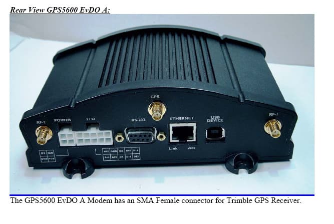
QWV-BTX600A
Dec 14, 2006CDMA Modem
Equipment Class
PCB - PCS Licensed Transmitter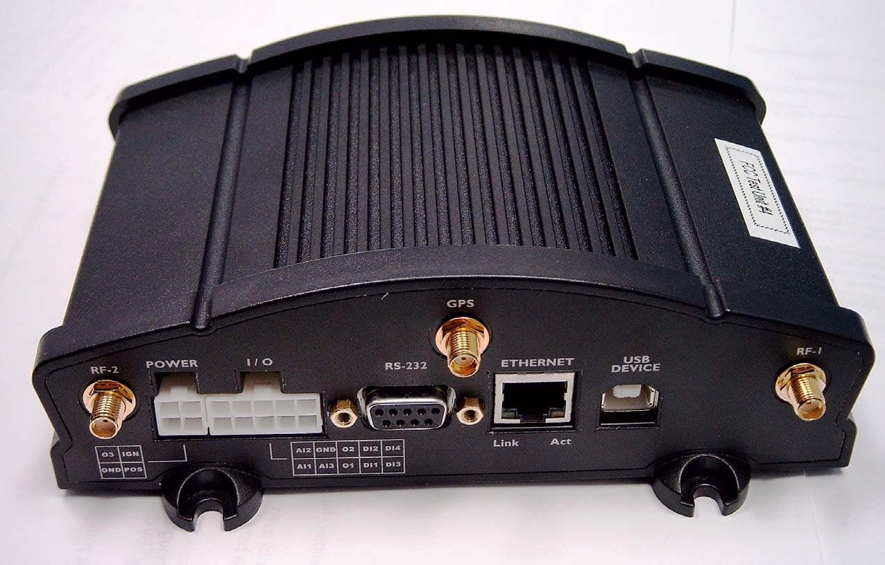
QWV-BTX600
Nov 21, 2005CDMA Wireless Radio Modem
Equipment Class
PCB - PCS Licensed Transmitter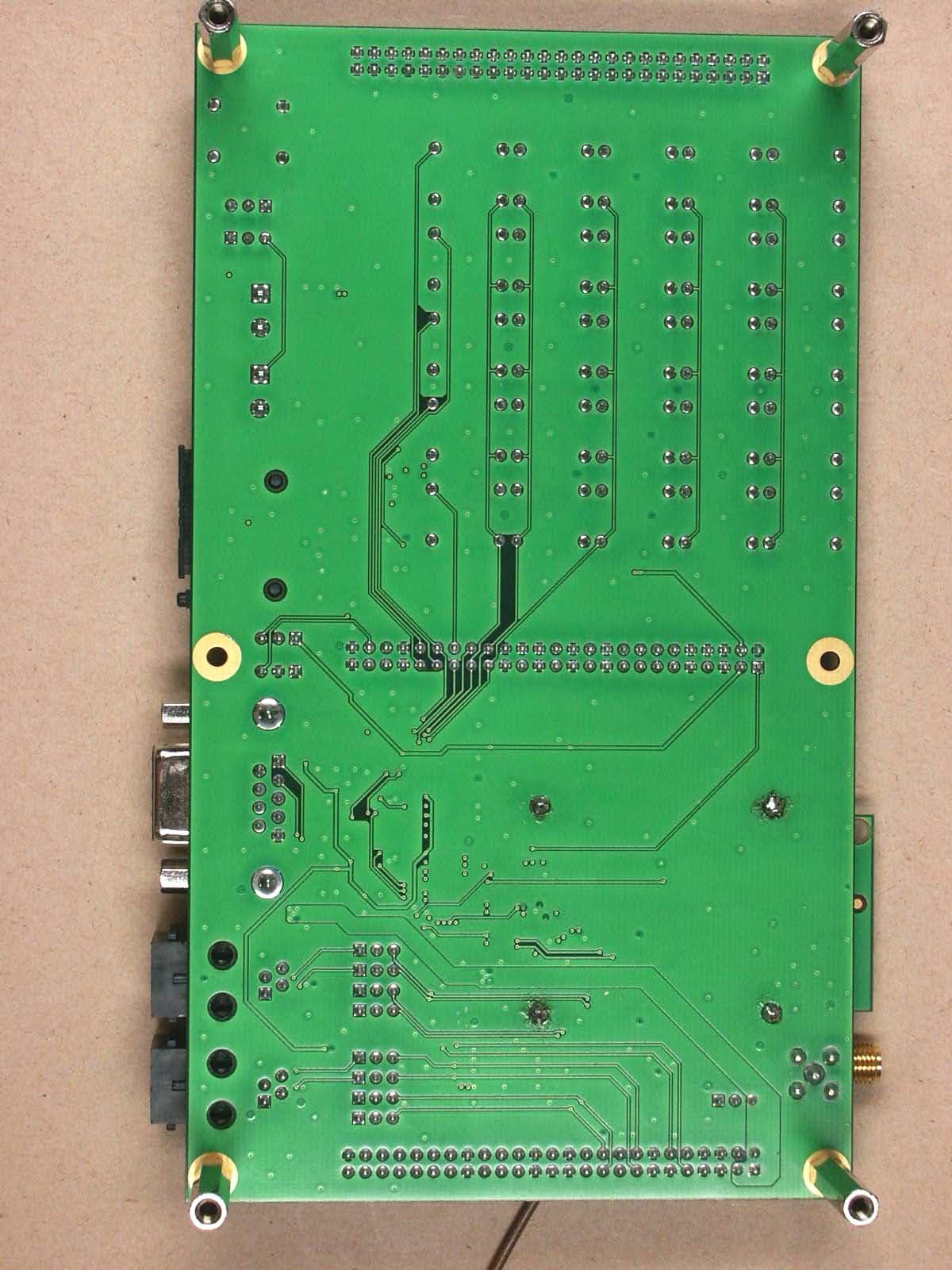
QWV-BT2000
Jul 26, 2004GSM/GPRS Wireless Modem
Equipment Class
PCB - PCS Licensed Transmitter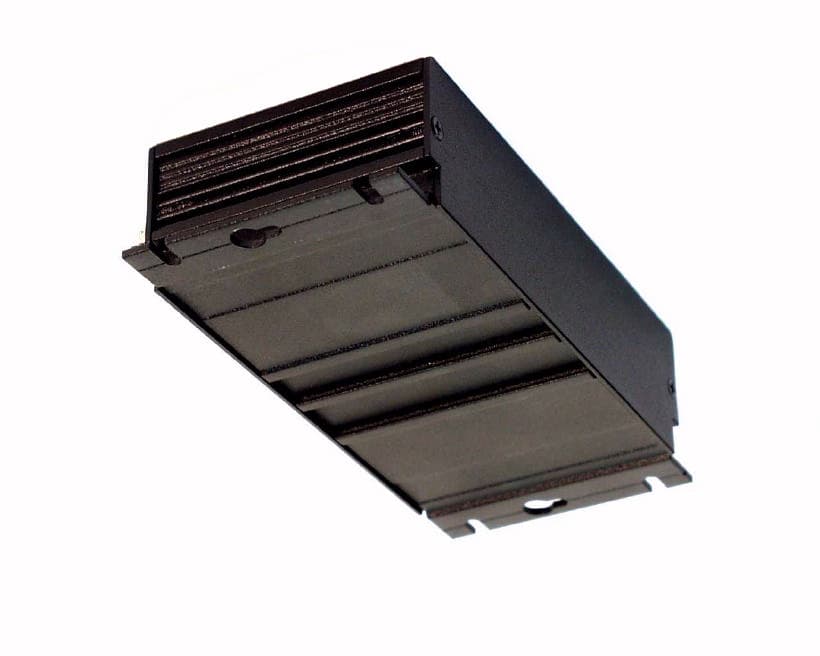
QWV-BTGPRS
Mar 10, 2003BT-GPRS-S
Equipment Class
PCB - PCS Licensed Transmitter