QWWFG-BT-3503Bluetooth GPS
Fortuna Electronic Corp.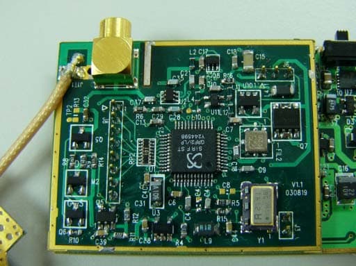
Click to zoom
Application Details
- Equipment Class
- DSS - Part 15 Spread Spectrum Transmitter
- Date of Grant
- Sep 28, 2003
- Application Purpose
- Original Equipment
- Date of Application
- Sep 28, 2003
- Equipment Note
- Bluetooth GPS
- Frequency Range
- 2402.00000000 - 2480.00000000
- Company
- Fortuna Electronic Corp.
- Country
- Taiwan
Documents & Files
Document Text
Text extracted from the exhibit documents filed with the FCC. Open a document above to read the original.
Users Manual
Introduction Overview The Fortuna Bluetooth GPS receiver is a Global Position System Receiver with Bluetooth wireless technology and SirF Xtrac technology. This Bluetooth GPS receiver allows you to receive GPS data on mobile handheld wirelessly. By sending GPS position data over Bluetooth, you can position with receiver for the best possible reception all without wires. The advent of Bluetooth GPS receiver will become the next level of GPS receivers. The SirF Xtrac technology is GPS software that can acquire and track lower signals than any other autonomous software solution. This means that it will enable the device to continue provide positions in places previously not possible. The Fortuna Bluetooth GPS receiver integrants Bluetooth module into GPS device, it shows the high performance, high sensitivity, low power consumption, easily portable, rechargeable& removable battery function and wireless data transmission. If you have a Pocket PC or other portable devices enabled with Bluetooth function, for example Ipaq 3870/3970 and O2 XDA, you can take advantage of your device’s Bluetooth capability to wirelessly add GPS positing technology. When you choose suitable navigation software, you can apply to personal, vehicle tracking, and marine navigation. If you use this Bluetooth GPS receiver, you will ignore the messy cords and antenna and add the portability of your pocket PC. In addition, This Bluetooth GPS receiver can change the exhausted battery to full battery like battery of mobile phone. Main Features 12 Channels “ All-In-View” Tracking XT – (SirF Xtrac) and ST – (Standard mode) Switch able (Fortuna Patent Pending) Position accuracy of 10 meters 2D RMS Cold/ Warm/ Hot Start Time: 45/38/8 Seconds Reacquisition Time: 0.1 seconds RF connector for external GPS antenna Support Standard NMEA-0183 at 38400 bps baud rate Support WAAS / EGNOS auto switch Compatible with Bluetooth devices with Serial Port Profile (SPP) Superior Sensitivity for Urban Canyon and Foliage Environment Small, sleek, and lightweight design easily fits in your hand Three LED at the top of the device show Bluetooth, GPS and Power Status. Detachable Lithium-Polymer battery lasts for more than 7.5 hours of use On/Off Switch button Dimension: L= 74 mm X W= 41.5mm X H= 30 mm Technical Specifications Electrical Characteristics General Chipset SiRF Star Ile/LP; SiRF Xtrac Frequency L1, 1575.42 MHz C/A code 1.023 MHz chip rate Channels 12 channel all-in-view tracking Antenna Type Built-in Ceramic patch antenna (External antenna optional) Accuracy Position 10 meters, 2D RMS 7 meters 2D RMS, WAAS corrected 1-5 meters, DGPS corrected Velocity 0.1 meters/ second Time 1 microsecond synchronized to GPS time Datum Default WGS-84 Acquisition Rate( Open sky, stationary) Standard Mode Reacquisition 0.1 sec., average Snap start 2 sec., average Hot start 8 sec., average Warm start 38 sec., average Cold start 45 sec., average Acquisition Rate ( Open Sky, Stationary) Xtrac Mode Reacquisition 100 msec Continuous 1 sec. Hot Start <4 sec. Warm Start <35 sec. Cold Start <45 sec. Sensitivity XT Mode Tracking 16dB-Hz Hot Start 23dB-Hz Warm Start 28dB-Hz Cold Start 32dB-Hz Dynamic Conditions Altitude 18,000 meters (60,000 feet) max. Velocity 515 meters/second ( 1000 knots) max. Acceleration 4g, max. Power Operational Power 3.3 VDC ±10% Input Power 5VDC ± 10% Battery Source rechargeable and removable lithium Polymer battery with 5V DC input charging circuit (1200 mA) Operation Time 7.5 hours continuous operating after full charge Battery Charge time 3 Hours Approx. Main Interface Connection: Communication with host platform via Bluetooth Serial Profile Protocol messages NMEA 0183 output protocol Baud rage: 38400 bps Data bit: 8 Stop bit: 1 Output format: GGA ( 1 sec), GSA ( 1 sec), GSV ( 5 sec), RMC ( 1 sec), VTG ( 1 sec) Environmental Characteristics Operating temperature range -20°C to +60°C Humidity range 5% to 95 % No condensing Physical Characteristics Length 74 mm Width 41.5 mm Height 30 mm Weight 95g Applications Fortuna GPS Bluetooth receiver is a high performance, low power consumption product. The product applications are as follow. Vehicle Tracking & Location-based Services Personal/ Portable Navigation Car Navigation Marine Navigation Operation and Test Hardware Description LED Light Status Description GPS Red Not Fix / ST Mode Standard mode, GPS is searching for Satellites Green Fix / ST Mode Standard mode, GPS is Fix, ready for Navigation Orange XT mode Xtrac mode Activated BT Blue Blinking Bluetooth function linking and Transferring data Power Red Power low Battery is low power status Green Normal Battery is in normal status Orange Charging Battery is charging “Dual Mode” Hardware Switch ST - (Standard) Recommended usage: When using the ST Mode we recommend the user to use it under clear open sky condition for car navigation. XT - (Xtrac) Recommended usage: When using the XT Mode we recommend the user to use it under more crowed environment. For example cover garages, multi-level roads, dense foliage cover, and many indoor environments. Caution 1. When switch between the ST mode and XT mode the user must turn off the BT GPS device. 2. When using XT mode on a high-speed environment some delay will be visible. 3. After the GPS device change to XT or ST mode the unit will automatically switch to cold start. BT Setting for PC or NB Before you use GPSmart BT connect with PC or NB, you need to have Bluetooth driver and Bluetooth device for PC or NB. Please turn on Bluetooth function in GPSmart BT. As follow: The follow steps of setting Bluetooth function in PC or NB. (1) Enter in “Bluetooth Configuration” and select “ My Bluetooth Place Neighborhood”. Bluetooth Configuration (2) In “ My Bluetooth Place”, you will see “ Entire Bluetooth Neighborhood”. Then, you have to press right button of mouse to open “ SPP Slave” window. (3) It will search GPSmart BT devices in range. (4) After enter “ GPSmart”, the screen will display “ SPP Slave”. …
Text truncated - open the document above for the full version.
Block Diagram
5 5 4 4 3 3 2 2 1 1 DD CC BB AA Title SizeDocument NumberRev Date:Sheetof A CSR BC02_External ClassII module B 11Tuesday, September 23, 2003 2.4GHz Radio RAM DSP MCU I/O CSR BC212015 SPI UART/USB PIO PCM 4/8M bits Flash ROM 16MHz X'tal RF IN RF Out BalunFilter CSR BC212015 funciton Description: 1. Single chip radio and baseband IC for Bluetooth 2.4GHz system. 2. Connection type: Frequency hopping 3. Transmission Power: Up to 4dBm 4. Frequency: ISM band 2400~2483.5MHz 5. Modulation: GFSK with BT(0.5) and modulation indes( 0.28~0.35) 6. Data Rate: 1Mbps Bandpass filter funciton Description: 1. Part: Soshin MDR741F. 2. Passband:2400~2500MHz 3. Attenuation: 25 dB min (at 1750MHz) 25 dB min (at 2100MHz) 22 dB min (at 4800-5000MHz Balun funciton Description: 1. Balance to unblance circuit transfor Flash Memory function Description: 1. Store CSR BC02 chip's firmware
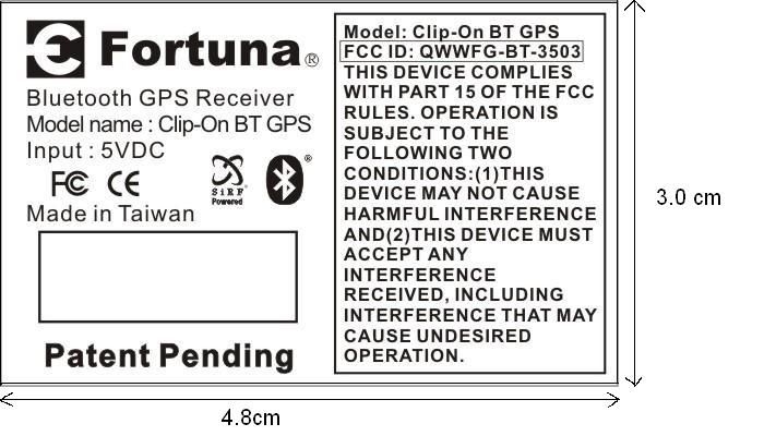
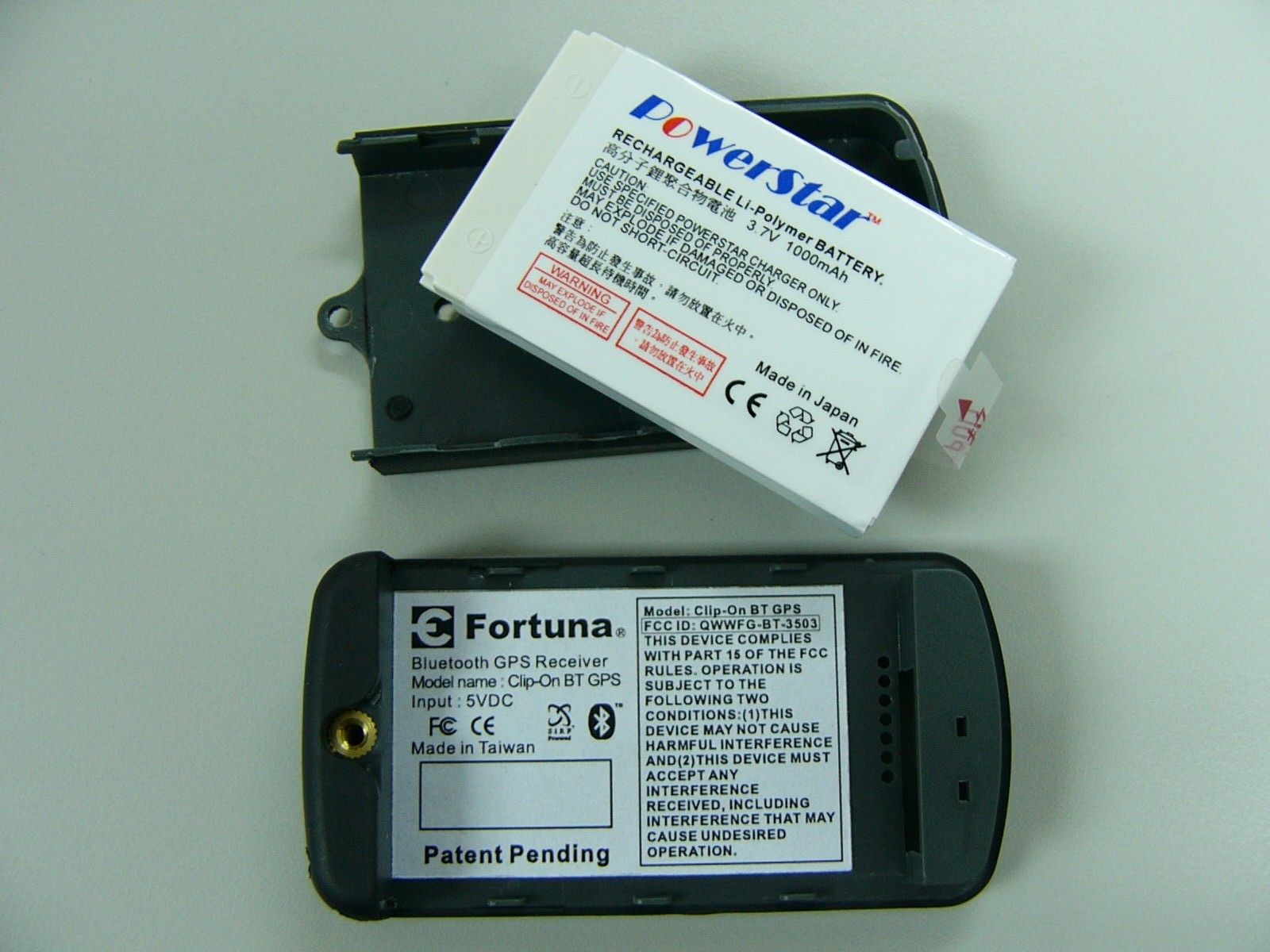
External Photos
External Photos
Internal Photos
Internal Photos
Operational Description
TECHNICAL SPEC. BLUETOOTH MODULE 1. InterfaceUSB/UART/PCM 2. output power +4dBm max(Class 2) 3. working distance10meter 4. Frequency band2.4GHz unlicensed ISM band 5. ModulationGFSK (Gaussian Frequency Shift Keying) 6. Connection modeActive, Hold, Sniff, Park 7. DC power3.3 ~ 3.6V 8. Sensitivity-80dBm @ 0.1BER 9. Data rate723K bps(max.) 10. Link modeACL and SCO link GPS MODULE GPS RF FRONT END GRF2i/LP PRELIMINARY GPS RF Sirf StarII z High speed signal acquisition using 1920 time/frequency search channels z Wide Area Augmentation System (WAAS) and NDGPS/U.S. Coast Guard Beacon support z Satellite signal-tracking engine for GPS acquisition and tracking functions without CPU intervention z Cold start under 45 seconds Maximizes GPS Position Availability z SingleSat updates in reduced visibility z Superior urban canyon performance z FoliageLock for weak signal tracking Cost Effective RFIC Integration z Built-in IF Filter z Integrated LNA z On-Chip VCO and Reference Oscillator z Single-stage L1 to IF Downconversion z External +/-25 ppm Reference Crystal z Power control eliminates the need for CPU crystal in TricklePower mode Seamless Interface to GSP2e Family z Standard 3.3V supply z Compatible with Standard Active Antennas z LQFP48 Package ( 7 * 7mm ) z Separate RF and Clock Power down mode z Simplified interface connections Maximum Performance z On-Chip 2-Bit A/D z Improved Jam Immunity z Low Overall NF GPS ENGINE PROCESSOR GPS 2e/LP PRELIMINARY SiRFstarII Architecture z Advanced TricklePower mode for power savings up to 98% with no extra parts z Extreme low power in power-down mode, but capable of very fast starts Maximizes GPS Position Availability z SingleSat updates in reduced visibility z Superior urban canyon performance z FoliageLock for weak signal tracking GPS2e Product Hightlights Highly Integrated Digital IC z Enhanced SiRFstarII GPS core z Integrated ARM7TDMI TM up to 50 MHz z Support 8-, 16-, and 32-bit data bus operation z Separate internal and external buses z On-chip 1 Mb EDO DRAM for GPS navigation z Instruction cache to improve throughput z Integrated high-precision Real-Time Clock z Extensive GPS peripherals 2 UARTS, synchronous serial bus, battery-backed SRAM, and >40 GPIO z QFP and BGA packaging options High Quality z 99% effective fault coverage z End-to-end simulation z ARM7TDMI with JTAG interface z Memory with Built-In Self-Test(BIST) Compute Power for User Applications z Up to 90% CPU throughput available for user tasks z Robust development environment BATTERY Li-Polymer Rechargeable Battery LED Power on: (a) Battery low: Orange LED on (b) Normal Battery voltage: Green LED on Power off: All LED off. MAXIMUM ABSOLUTE VALUES ITEM SYMBOL MIN Max UNITS Operating temperature Top -20 +70 0 C Storage temperature Tst -30 +80 0 C Supply voltage for logic VDD -0.3 +5.0 V Supply voltage for battery V 0 -0.3 +5.0 V
Schematics
csr Cambridge Science Park, Milton Road Cambridge, CB4 0WH, United Kingdom. Tel. +44 (0)1223 692000 Fax. +44 (0)1223 692001 http://www.csr.com R422R J5 J6 J13 J11 J14 J22 J10 J7 J21 J20 J19 J31 J30 J28 J27 J25 J24 J1 J17 J16 J15 C1 47p +1V8 C3 1p8 3n9 L2 C7 220p (COG) C4 10n C5 10n +1V8+1V8 2u2 C8 R3 0R +3V3 C13 10n C10 10n +3V3 +1V8 +1V8 C16 100n R7 1K 2u2 C14 J4 J23 J12 J18 J9 J8 J29 J26 J3 J2 4 OUT 1 IN 2 GND 3 GND MDR741F U3 3n9 L3 1p8 C2 R2 180K +1V8 VMEM +1V8 16MHz X1 +1V8 J34 J32 TP2 J33 TP1 C6 NF NF R1 L1 3n9 R6 0R0 VMEM C9 47p 3p3 C11 VMEM C15 100n R5 22R 10p C12 +3V3 2 GND 3 CE 4 NC 1 Vin 5 Vout XC6204B182MR U4 54 123 6 N/C T1 HHM-1517 G4 VCC H1 VSS F6 B YTE F1 CE C3 A18 D6 A15 B6 A12 A5 A9 C2 A6 A1 A3 E1 A0 D4 A19 H6 VSS A4 WE G1 OE B4 RESET A2 A7 B5 A8 C5 A10 D5 A11 A6 A13 C6 A14 E6 A16 D1 A1 C1 A2 B1 A4 B2 A17 D2 A5 D3 NC A3 RY/BY F4 DQ12 G2 DQ9 H5 DQ6 H3 DQ3 E2 DQ0 B3 NC C4 NC E5 DQ7 F2 DQ8 F3 DQ10 G3 DQ11 G5 DQ13 F5 DQ14 H2 DQ1 E3 DQ2 H4 DQ4 E4 DQ5 G6 DQ15A-1 U2 AM29LV800B D10 REB E9 A[1] F10 A[4] G10 A[7] L9 D[1] L8 D[4] L7 D[7] J2 VSS_VCO K1 VDD_ANA F2 VSS_RADIO A9 VSS_CORE D1 VDD_RADIO C11 VSS_MEM A10 VDD_PADS H10 A[10] J9 A[13] K9 A[16] L1 XTAL_IN L6 D[10] L5 D[13] C7 VSS C10 CSB E11 A[2] E10 WEB D9 A[0] F11 A[5] G11 A[8] H9 A[9] G9 A[6] L10 D[2] J7 D[5] K8 D[0] L11 D[3] J6 D[8] K6 D[9] G2 VSS_RADIO A11 VSS_PADS L3 VSS_ANA E2 VSS_RADIO H3 VDD_RADIO A1 VDD_PIO H1 VDD_VCO H11 A[11] J10 A[14] J8 A[12] A8 VDD_CORE D11 VDD_MEM K10 A[17] K11 A[18] J5 D[11] J4 D[14] K5 D[12] K4 D[15] L2 XTAL_OUT J3 AIO[2] G3 TEST_EN B6 UART_CTS B4 SPI_MISO B8 PCM_CLK B11 PCM_SYNC C2 PIO[1] B1 PIO[4] E3 PIO[7] C5 PIO[10] F9 A[3] J1 LOOP_FILTER H2 VSS_VCO D2 AUX_DAC G1 TX_A F1 TX_B E1 RF_IN K7 D[6] F3 RESET B7 UART_RTS C9 UART_RX C8 UART_TX L4 AIO[1] A7 USB_D+ A5 SPI_MOSI B10 PCM_IN A4 SPI_CSB B5 SPI_CLK B9 PCM_OUT C4 PIO[9] D3 PIO[8] C3 PIO[6] A3 PIO[5] B2 PIO[3] B3 PIO[2] C1 PIO[0] A2 VSS_PIO J11 A[15] A6 USB_D- K3 AIO[0] K2 VSS_ANA C6 PIO[11] U1 BC212015ADN-E4
Test Report
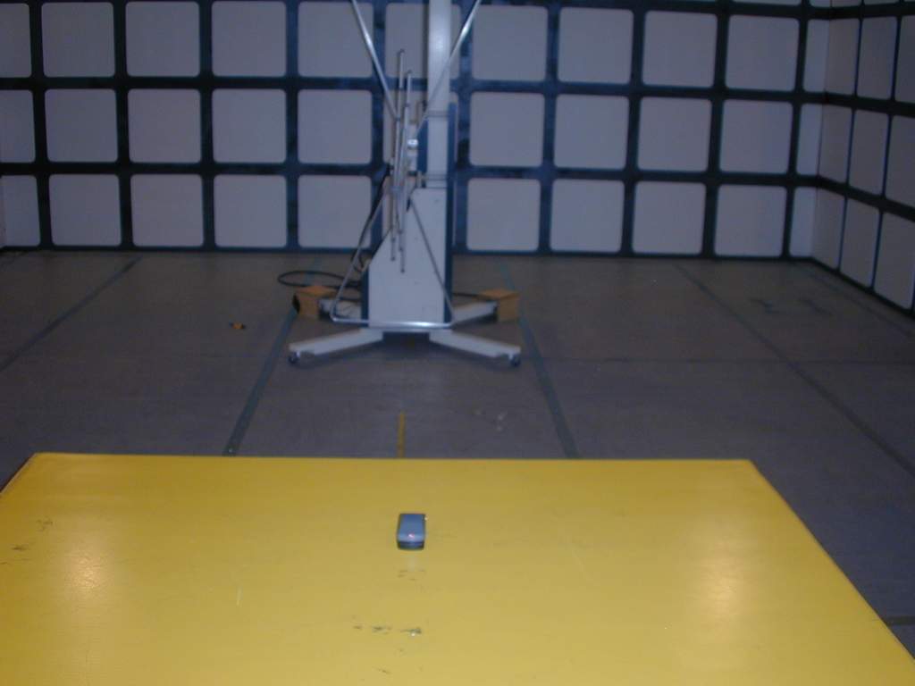
Report No. : ER/2003/80017 Page : 1 of 44 TEST REPORT Equipment Under Test : Bluetooth GPS Model No. : Clip-On BT GPS Applicant : Fortuna Electronic Corp 3F, No.9, Sec. 1, ChangAn East Road, Taipei, Taiwan, R.O.C. Address of Applicant : Standards: FCC Part 15 subpart C In the configuration tested, the EUT complied with the standards specified above. Remarks: This report details the results of the testing carried out on one sample, the results contained in this test report do not relate to other samples of the same product. The manufacturer should ensure that all products in series production are in conformity with the product sample detailed in this report. This report may only be reproduced and distributed in full. If the product in this report is used in any configuration other than that detailed in the report, the manufacturer must ensure the new system complies with all relevant standards. Any mention of SGS Taiwan E&E Services or testing done by SGS Taiwan E&E Services in connection with distribution or use of the product described in this report must be approved by SGS Taiwan E&E Services in writing. Tested by : Alex Hsieh Testing Date : Sep. 08, 2003 Approved by : Robert Chang Issue Date : Sep. 09, 2003 Report No. : ER/2003/80017 Page : 2 of 44 Contents 1. General Information 1.1 Testing Laboratory 3 1.2 Details of Applicant 3 1.3 Description of EUT(s) 3 1.4 Operation Procedure 4 1.5 Testing Method 4 2. Summary of Results 6 3. Instruments List 7 4. Measurements 8 4.1 Radiated emission Limits, general requirement 8 4.2 Channel Spacing 15 4.3 20db bandwidth / No. of channels 16 4.4 Average time of Occupancy 21 4.5 Peak output power 25 4.6 Band-edge emission 28 4.7 Spurious Emission under 25Ghz 30 APPENDIX Photographs of Test Setup 42 Photographs of EUT 43-44 Report No. : ER/2003/80017 Page : 3 of 44 1. General Information 1.1 Testing Laboratory SGS Taiwan Ltd. ( FCC Registration number: 573967 ) 1F, No. 134, Wukung Road, Wuku industrial zone Taipei county , Taiwan , R.O.C. Telephone : +886-2-2299-3279 Fax : +886-2-2298-2698 Internet : http://www.sgs.com.tw 1.2 Details of Applicant Applicant : Fortuna Electronic Corp Address of Applicant : 3F,No.9,Sec. 1,ChangAn East Road, Taipei, Taiwan, R.O.C. Contact : Vincent Chen Telephone : +886-2-25818373 ext. 280 1.3 Description of EUT(s) 1 Product name Bluetooth GPS 2 Product ID Clip-On BT GPS 3 Supply Voltage DC 3.7V 4 Antenna Gain 0 dbi 5 Carrier Frequency 2402MHz to 2480MHz 6 Modulation Method GFSK,1Mbps,0.5BT Gaussian 7 Hopping 1600hops/sec, 1MHz channel space 8 Operation Temperature -20 to +55 degree 9 Compliant Bluetooth Specification Ver1.1 Report No. : ER/2003/80017 Page : 4 of 44 1.4 Operation Procedure The Bluetooth is a FHSS system, and the output power and operating frequency are NOT End-user adjustable. Applicant offer a engineering software “BlueSuite” installed on PC to control the EUT. Setting of the software parameters are set as default. Operating frequency are set as testing required. The output power is set as Ext=255, Int=60 (at max. power). Inside the BlueSuite software, there is a BlueTest to control EUT hopping on or off. We select “Txdata1” (which modulated by pseudo-random sequence)and assign the transmit channel(as below). When the EUT is required to transmit in hopping on mode. We select “Txdata2” The lowest operating frequency within Bluetooth specification is 2402Mhz, and highest operating frequency is 2480Mhz. So the frequency above are used as the lowest and highest frequency in the testing, and the middle frequency is set as 2441Mhz. 1.5 Testing Method The testing standard follows CFR 47, Part 15.247 and ANSI C63.4 1992, and measurement method according to Public Notice DA00-705 (March 2000). The Testing procedure is as following: a. The EUT was connected to PC via RS232 and placed on the top of a rotating table 0.8 meters above the ground at a 3m chamber. The table was rotated 360 degrees to determine the position of the highest radiation. b. The EUT was set 3 meters away from the interference-receiving antenna. c. The antenna is a broadband antenna, and its height is varied from one meter to four meters above the ground to determine the maximum value of the field strength. Both horizontal and vertical polarizations of the antenna are set to make the measurement. d. For each suspected emission, the EUT was arranged to its worst case and then the antenna was tuned to heights from 1 meter to 4 meters and the turn table was turned from 0 degrees to 360 degrees to find the maximum reading. e. The test-receiver system was set to Peak Detect Function and Specified Bandwidth with Maximum Hold Mode. Report No. : ER/2003/80017 Page : 5 of 44 NOTE: 1. The resolution bandwidth and video bandwidth of test receiver/spectrum analyzer is 120kHz for Peak detection (PK) and Quasi-peak detection (QP) at frequency below 1GHz. 2. The resolution bandwidth and video bandwidth of test receiver/spectrum analyzer is 1 MHz for Peak detection at frequency above 1GHz. 3. The resolution bandwidth of test receiver/spectrum analyzer is 1 MHz and the video bandwidth is 300 Hz for Average detection (AV) at frequency above 1GHz. 4. During the Output power testing, the manufacturer attach a test fixture which is a short cable that replace the antenna. So we use conducted method to measure the power. Hence the EIRP is the output power plus the antenna gain in dBi. Due to cable loss, the real value will equal to measured value(show on the instrument) add cable loss. Report No. : ER/2003/80017 Page : 6 of 44 2.Summary of Results subclause Parameter to be measures Verdict Page 15.209 Radiated emission Limits, general requirement PASS 8 15.247(a)(1) Channel Spacing PASS 15 15.247(a)(1)(ii) 20db bandwidth / No. of channels PASS 16 15.247(a)(1)(ii) Average Time of Occupancy PASS 21 15.247(b)(1) Peak Output power PASS 25 15.247(c) Band-Edge Emission PASS 28 15.247(c) Spurious Emission under 25Ghz PASS 30 Report No. : ER/2003/80017 Page : 7 of 44 3. I…
Text truncated - open the document above for the full version.
Contact Information
Applicant
Mike Hsu(President)
Test Firm
SGS Taiwan Ltd.Wyse Chiu
Technical Specifications
| # | Rule Parts | Frequency Range | Power Output |
|---|---|---|---|
| 1 | 15C | 2.40 GHz - 2.48 GHz | 3.15 mW |
Other Applications from Fortuna Electronic Corp.
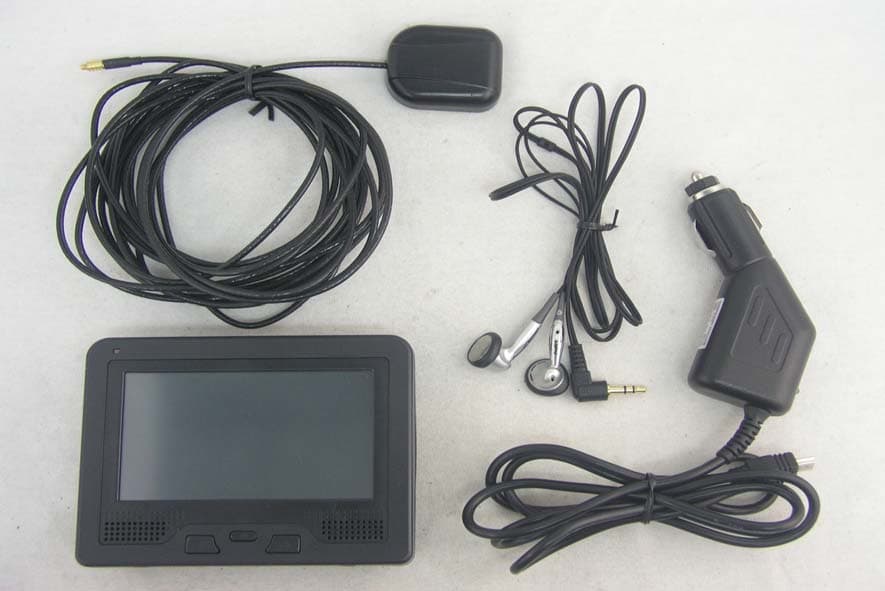
QWW-610B
Jan 01, 2007GPS-receiver
Equipment Class
DSS - Part 15 Spread Spectrum Transmitter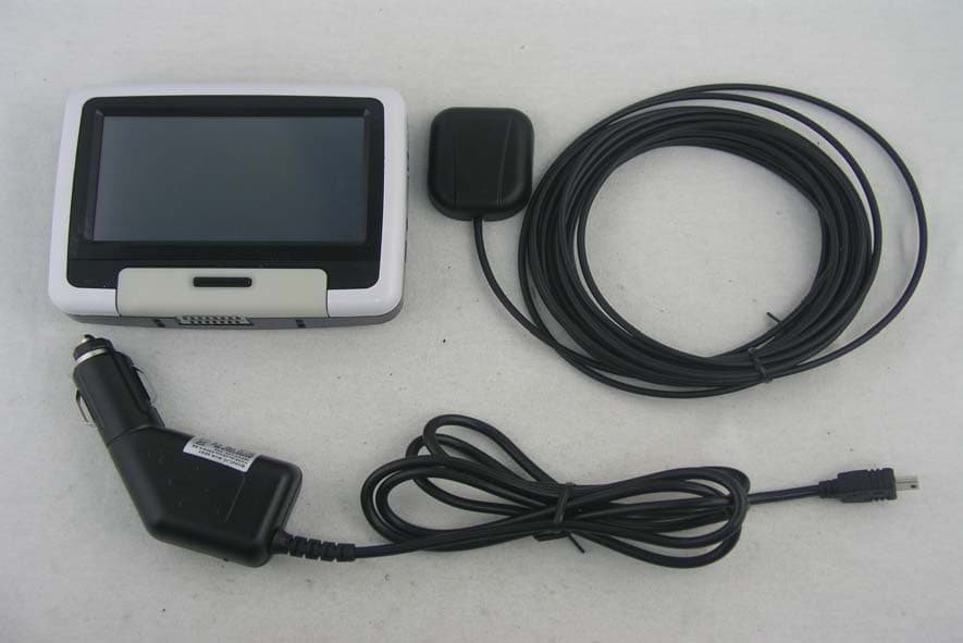
QWW-455
Dec 17, 2006GPS Receiver with Bluetooth
Equipment Class
DSS - Part 15 Spread Spectrum Transmitter
QWWFG-BT-1505
Apr 26, 2005Bluetooth Slim GPS Transceiver
Equipment Class
DSS - Part 15 Spread Spectrum TransmitterQWWFG-BT-1804
May 27, 2004Slim GPS
Equipment Class
DSS - Part 15 Spread Spectrum Transmitter
QWWFG-BT-0803
Mar 20, 2003GPS Handheld Bluetooth
Equipment Class
DSS - Part 15 Spread Spectrum Transmitter