QYO-COLLECTOR-PData Collector
KEMP-MEEK, Inc.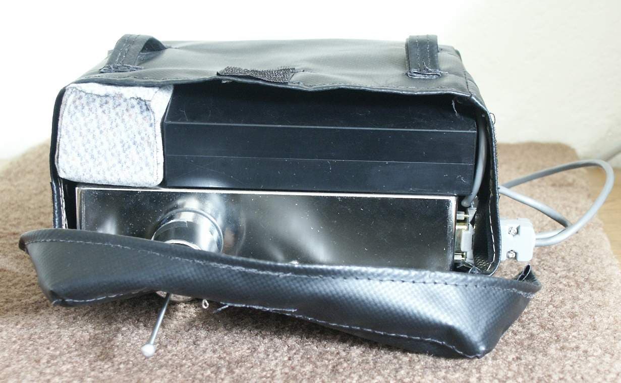
Click to zoom
Application Details
- Equipment Class
- DSS - Part 15 Spread Spectrum Transmitter
- Date of Grant
- Apr 17, 2006
- Application Purpose
- Original Equipment
- Date of Application
- Apr 17, 2006
- Equipment Note
- Data Collector
- Frequency Range
- 922.70000000 - 927.90000000
- Company
- KEMP-MEEK, Inc.
- Country
- United States
Documents & Files
Document Text
Text extracted from the exhibit documents filed with the FCC. Open a document above to read the original.
Users Manual
Metre Pro Technologies Collector-Portable User’s Guide 1 Overview This document covers the Collector-P (portable) series of radio transceivers designed and manufactured by Metre Pro Technologies, Inc. It is intended to guide the user through the proper setup and operation of the Collector-P. Failure to strictly adhere to this guide may cause improper operation and/or damage to the unit, and this could result in voiding of all warranties. Authority to Operate Equipment THIS EQUIPMENT COMPLIES WITH PART 15 OF THE FCC RULES. ANY CHANGES OR MODIFICATIONS NOT EXPRESSLY APPROVED BY THE MANUFACTURER COULD VOID THE USER’S AUTHORITY TO OPERATE THE EQUIPMENT. Product Description The Collector-P is a portable radio transceiver specifically designed to provide automated meter reading applications to industry, providing a low cost and high reliability solution. It establishes a wireless link to the ER series of radio transceivers located at the meters. Attached to the hip of a utility worker walking near these meters, the primary purpose of the Collector-P is to collect data from ER series radio transceivers connected to those meters and transfer this data to a handheld computer. Contact your account manager or distributor regarding the ER series radio transceivers. Performance The performance of the Collector-P and any other radio frequency device is subject to many factors. Some of these factors are: interference from other radio frequency sources, soil and soil moisture, buildings, proximity to surrounding objects, and weather. The Collector-P is designed for optimum performance, however, the above factors may enhance or degrade performance. Consult Metre Pro Technologies if performance issues occur. Enhancements and Design Changes Metre Pro Technologies is continually improving and enhancing its products and services. We reserve the right to make product, service, and specification changes without notice. Repairs and Service This product is not field repairable. In the event of a failure, contact your account manager or distributor for assistance in returning the product and getting replacements. Metre Pro liability is limited solely to the replacement of the device and excludes labor 2 and other costs. The purchase of this product implies an agreement to all restrictions, guides, and terms contained within this document. Training Metre Pro offers an instructor-led training program for those involved in the use, sales, installation, or marketing of the full line of Metre Pro products and services. Contact your account manager or distributor for more details. Collector-P Installation 1. Connect battery pack power plug if not already connected. 2. Route belt through the hip belt loops on the Collector-P carrying case. This carrying case contains the Collector-P with its integral vertical antenna and its battery pack. Note that the antenna only fits through the hole in the carrying case one way, in a position which keeps the antenna about 2.5 inches or more from the body. WARNING: The portable antenna is designed so that in normal use it is more than 2 inches from the body. It should maintain a distance of at least 1 inch (2.5 cm) from the body while transmitting. Failure to install this device as described will result in a failure to comply with FCC rules for radio frequency exposure and is discouraged. 3. Connect the handheld computer’s serial cable to the Collector-P’s serial port. 4. Follow instructions for the handheld computer software application to transmit a signal to retrieve a meter reading when walking near a meter equipped with an ER series transponder. WARNING: The antenna rod is permanently attached to the magnetic base. Do not attempt to remove it. 3
ID Label/Location Info
FCC ID Label Information for FCC Type Acceptance on QYO-COLLECTOR-P The FCC ID label will be located along the top edge of Collector-P housing and is designed to last the lifetime of the product. 2.75” 1.5”
Test Report
Nemko Test Report: 5L0470RUS1 Applicant: Kemp-Meek Manufacturing 101 Park Central Mineola, TX 75773 Equipment Under Test: COLLECTOR-P In Accordance With: FCC Part 15, Subpart C, 15.247 Frequency Hopping Transmitters Tested By: Nemko USA Inc. 802 N. Kealy Lewisville, Texas 75057-3136 Authorized By: David Light, Senior Wireless Engineer Date: 21 December 2005 Nemko USA FCC PART 15, SUBPART C FREQUENCY HOPPING SPREAD SPECTRUM TRANSMITTER EQUIPMENT: COLLECTOR-P PROJECT NO.: 5L0470RUS1 Page 2 of 40 Table of Contents Section 1. Summary of Test Results .....................................................................3 Section 2. Equipment Under Test (E.U.T.) ...........................................................5 Section 3. Channel Separation...............................................................................7 Section 4. Time of Occupancy ............................................................................10 Section 5. Occupied Bandwidth and Bandedges.................................................12 Section 6. Peak Power Output .............................................................................18 Section 7. Spurious Emissions (Antenna Conducted).........................................19 Section 8. Spurious Emissions (Radiated) ..........................................................22 Section 9. Test Equipment List ..........................................................................29 ANNEX A - TEST DETAILS .................................................................................30 ANNEX B - TEST DIAGRAMS.............................................................................38 Nemko USA FCC PART 15, SUBPART C FREQUENCY HOPPING SPREAD SPECTRUM TRANSMITTER EQUIPMENT: COLLECTOR-P PROJECT NO.: 5L0470RUS1 Page 3 of 40 Section 1. Summary of Test Results Manufacturer: Kemp-Meek Manufacturing Model No.: COLLECTOR-P Serial No.: NA General: All measurements are traceable to national standards. These tests were conducted on a sample of the equipment for the purpose of demonstrating compliance with Part 15, Subpart C, Paragraph 15.247 for Frequency Hopping Spread Spectrum devices. Radiated tests were conducted is accordance with ANSI C63.4-2003. Radiated emissions are made on an open area test site. A description of the test facility is on file with the FCC. New Submission Production Unit Class II Permissive Change Pre-Production Unit Family Listing THIS TEST REPORT RELATES ONLY TO THE ITEM(S) TESTED. THE FOLLOWING DEVIATIONS FROM, ADDITIONS TO, OR EXCLUSIONS FROM THE TEST SPECIFICATIONS HAVE BEEN MADE. See “ Summary of Test Data”. NVLAP LAB CODE: 100426-0 Nemko USA Inc. authorizes the above named company to reproduce this report provided it is reproduced in its entirety and for use by the company’s employees only. Any use which a third party makes of this report, or any reliance on or decisions to be made based on it, are the responsibility of such third parties. Nemko USA Inc. accepts no responsibility for damages, if any, suffered by any third party as a result of decisions made or actions based on this report. This report applies only to the items tested. Nemko USA FCC PART 15, SUBPART C FREQUENCY HOPPING SPREAD SPECTRUM TRANSMITTER EQUIPMENT: COLLECTOR-P PROJECT NO.: 5L0470RUS1 Page 4 of 40 Summary Of Test Data NAME OF TEST PARA. NO. SPEC. RESULT Powerline Conducted Emissions 15.207(a) 48 dBμV NA Channel Separation 15.247(a)(1) Greater of 25 kHz or 20 dB Bandwidth COMPLIES Pseudorandom Hopping Algorithm 15.247(a)(1) COMPLIES NOTE1 Time of Occupancy 15.247(a)(1)(ii) ≤ 0.4 sec in 20 sec COMPLIES 20 dB Occupied Bandwidth 15.247(a)(1) ≤ 1 MHz COMPLIES Peak Power Output 15.247(b) 1 Watt COMPLIES Spurious Emissions (Antenna Conducted) 15.247(c) -20 dBc COMPLIES Spurious Emissions (Radiated) 15.247(c) Table 15.209(a) COMPLIES Footnotes: NOTE 1 CUSTOMER WILL PROVIDE IN DOCMENTATION NA THE EUT IS BATTERY POWERED DEVICE Nemko USA FCC PART 15, SUBPART C FREQUENCY HOPPING SPREAD SPECTRUM TRANSMITTER EQUIPMENT: COLLECTOR-P PROJECT NO.: 5L0470RUS1 Page 5 of 40 Section 2. Equipment Under Test (E.U.T.) General Equipment Information Frequency Band: 902 – 928 MHz 2400 – 2483.5 MHz Number of Channels: 50 Operating Frequencies: 922.7 to 927.9 Channel Spacing: 100 kHz User Frequency Adjustment: Software controlled Nemko USA FCC PART 15, SUBPART C FREQUENCY HOPPING SPREAD SPECTRUM TRANSMITTER EQUIPMENT: COLLECTOR-P PROJECT NO.: 5L0470RUS1 Page 6 of 40 Theory of Operation FREQUENCY HOPPER TX TO COMMUNICATE WITH METERS System Diagram 12VDC BATTERY Nemko USA FCC PART 15, SUBPART C FREQUENCY HOPPING SPREAD SPECTRUM TRANSMITTER EQUIPMENT: COLLECTOR-P PROJECT NO.: 5L0470RUS1 Page 7 of 40 Section 3. Channel Separation NAME OF TEST: Channel Separation PARA. NO.: 15.247(a)(1) TESTED BY: Kevin Rose DATE: October 8, 2005 Test Results: Complies. Measurement Data: See attached plot Equipment Used: 1472, 1464, 1081, 1471 Measurement Uncertainty: +/- 1.7 dB Temperature: °21C Relative Humidity: 46% Nemko USA FCC PART 15, SUBPART C FREQUENCY HOPPING SPREAD SPECTRUM TRANSMITTER EQUIPMENT: COLLECTOR-P PROJECT NO.: 5L0470RUS1 Page 8 of 40 Channel Separation Ref 30 dBm 925.5195 MHz Att 30 dB 925.5195 MHz 925.5195 MHz 925.5195 MHz 925.5195 MHz 925.5195 MHz 925.5195 MHz 925.5195 MHz 925.5195 MHz 925.5195 MHz 925.5195 MHz Offset 30.2 dB 925.5195 MHz A 925.5195 MHz LVL 925.5195 MHz Center 925.5 MHz 925.5195 MHz Span 250 kHz 925.5195 MHz 25 kHz/ 925.5195 MHz * 925.5195 MHz RBW 10 kHz 925.5195 MHzVBW 30 kHz 925.5195 MHz SWT 2.5 ms 925.5195 MHz 1 PK 925.5195 MHz VIEW 925.5195 MHz -70 -60 -50 -40 -30 -20 -10 0 10 20 30 925.5195 MHz 1 Marker 1 [T1 ] 20.81 dBm 925.519500000 MHz 1 Delta 1 [T1 ] 0.57 dB -100.000000000 kHz MARKER 1 925.5195 MHz Date: 19.AUG.2005 14:36:56 Nemko USA FCC PART 15, SUBPART C FREQUENCY HOPPING SPREAD SPECTRUM TRANSMITTER EQUIPMENT: COLLECTOR-P PROJECT NO.: 5L0470RUS1 Page 9 of 40 Nemko USA FCC PART 15, SUBPART C FREQUENCY HOPPING SPREAD SPECTRUM TRANSMITTER EQUIPMENT…
Text truncated - open the document above for the full version.
Contact Information
Applicant
J L Meek(President)
Technical Contact
Test Firm
Nemko USA, Inc.Tom Tidwell
Technical Specifications
| # | Rule Parts | Frequency Range | Power Output |
|---|---|---|---|
| 1 | 15C | 922.7 MHz - 927.9 MHz | 145.00 mW |
Other Applications from KEMP-MEEK, Inc.
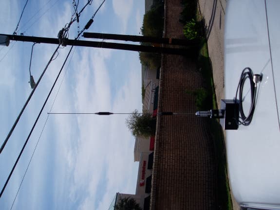
QYOTRUCKRADIO
Oct 28, 2003Meter Interrogation Device
Equipment Class
DSS - Part 15 Spread Spectrum Transmitter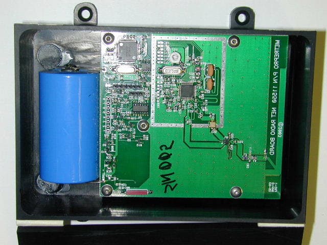
QYONETRADIO
Apr 07, 2003Wireless meter reading device
Equipment Class
DSS - Part 15 Spread Spectrum Transmitter