QYONETRADIOWireless meter reading device
KEMP-MEEK, Inc.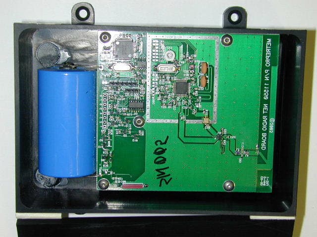
Click to zoom
Application Details
- Equipment Class
- DSS - Part 15 Spread Spectrum Transmitter
- Date of Grant
- Apr 07, 2003
- Application Purpose
- Original Equipment
- Date of Application
- Apr 07, 2003
- Equipment Note
- Wireless meter reading device
- Frequency Range
- 902.10000000 - 907.80000000
- Company
- KEMP-MEEK, Inc.
- Country
- United States
Documents & Files
Document Text
Text extracted from the exhibit documents filed with the FCC. Open a document above to read the original.
Users Manual
P.O. Box 670, 101 Park Central Mineola, TX 75773 903-569-9700 Fax 903-569-9696 Net Radio Users’ Guide Overview This document is intended to guide the user /installer through the Proper set up and field installation of the Net Radio. NOTE: failure to strictly adhere to this guide could result in voiding all warranties. Warning This equipment complies with Port 15 of the FCC Rules. Any changes or modifications not expressly approved in writing by the Manufacturer could void the users’ authority to operate this Equipment.This device uses RF energy. No modification should be made to increase the trancmitted rf energy from this device. Scope This document covers the E.R. series of radio transceivers by Metre-Pro Technologies, Inc. Training Metre-Pro offers an instructor led training program for those involved in the use, sales, installation or marketing of the full Line of Metre-Pro products and services. Contact your distributor or account manager for more details. Enhancements and Design changes Metre-Pro is continually improving and enhancing its products and services. We reserve the right to make product, services and Specification changes without notice. Product Description The E.R. series of Metre-Pro Technologies radio transceivers were specifically designed for automated meter reading applications providing low cost and high reliability solutions. The E.R. series wireless link is the stationary device used to collect and store meter or other data. Then transmit that data a separate receiver station. Contact your account manager or distributor regarding receiver station options. Data Source Diversity The E.R. series of transceivers were designed to accept data from variety of sources. NOTE: Due to the variety of data sources which may be applied to the E.R. series of wireless links, strict adherence to installation procedures is required or all warranties will be null and void. Connect these devices only to those permitted in written Instructions provided exclusively by Metre-Pro Technologies. Performance The performance of any radio frequency device is subject to many factors. Some of these factors are, other R.F. sources, soil, soil moisture, water, buildings, metal objects, and even weather. The E.R. devices employ the best designs and best technology to optimize the performance, however, in any given situation actual performance can vary. Consult Metre-Pro Technologies if performance issues occur. Configuration The E.R. devices may be supplied in multiple configurations: Attached The E.R. device is attached to the data source (meters etc.) at the factory. Unattached The E.R. device is supplied with an exposed cable, length can vary as ordered, to which to which the data source can be connected In the field. See connection specifics. Pit Mounted The E.R. device is supplied with a mounting Stake. Wall Mounted The E.R. device is supplied with mounting Feet which allows attaching the device to Walls, etc. Connections Strict observance of the connection scheme is required For proper operation. Each exposed cable on the E.R. devices contain three Conductors. The conductors are color coded as follows: Red Green Black For data connections: Red is clock out Green is data in Black is ground For switch connections, piezo or Reed switches:: Black – switch negative Red – switch positive Consult the factory for the latest updated listing of Approved data sources and approved switches. Field Connections After determining the intended data source or Switch meets factory approval, connecting the device Should proceed as follows: 1. See and use the appropriate Installation Advisory Installation Advisories will Be added or changed as connectable Products evolve.. 2. The user/installer is responsible for Their own safety. When using tools Or equipment proper protection and Clothing should be used. It is the User/installer’s responsibility to assure The work area is safe.. General This product is not field repairable.. In the event Of a failure, contact your distributor or account Manager for assistance in returning product and Getting replacements. Metre-Pro liability is limited Solely to the replacement of the device and excludes Labor and other costs. The purchase of this product Implies an agreement to all the above restrictions, Guides and terms. END
Internal Photos
PCB in plastic housing PCB Back Side PCB Front Side
Test Report
Nemko Test Report: 2L0609RUS1 Applicant: Kemp-Meek Mfg. 101 Park Central Mineola, TX 75773 Equipment Under Test: NetRadio (E.U.T.) In Accordance With: FCC Part 15, Subpart C, 15.247 Frequency Hopping Transmitters Tested By: Nemko Dallas Inc. 802 N. Kealy Lewisville, Texas 75057-3136 Authorized By: Tom Tidwell, Frontline Manager Date: 3/6/03 Total Number of Pages: 38 Nemko Dallas FCC PART 15, SUBPART C FREQUENCY HOPPING SPREAD SPECTRUM TRANSMITTER EQUIPMENT: PROJECT NO.: 2L0609RUS1 Page 2 of 38 Table of Contents Section 1. Summary of Test Results..................................................................3 Section 2. Equipment Under Test (E.U.T.)........................................................5 Section 3. Channel Separation..........................................................................7 Section 4. Pseudorandom Hopping Algorithm...................................................9 Section 5. Time of Occupancy........................................................................12 Section 6. Occupied Bandwidth......................................................................15 Section 7. Peak Power Output.........................................................................19 Section 8. Spurious Emissions (Radiated).......................................................21 Section 9. Test Equipment List......................................................................25 ANNEX A - TEST DETAILS.............................................................................26 ANNEX B - TEST DIAGRAMS.........................................................................36 Nemko Dallas FCC PART 15, SUBPART C FREQUENCY HOPPING SPREAD SPECTRUM TRANSMITTER EQUIPMENT: PROJECT NO.: 2L0609RUS1 Page 3 of 38 Section 1. Summary of Test Results Manufacturer: Kemp-Meek Mfg Model No.: NetRadio Serial No.: None General: All measurements are traceable to national standards. These tests were conducted on a sample of the equipment for the purpose of demonstrating compliance with Part 15, Subpart C, Paragraph 15.247 for Frequency Hopping Spread Spectrum devices. Radiated tests were conducted is accordance with ANSI C63.4-1992. Radiated emissions are made on an open area test site. A description of the test facility is on file with the FCC. New Submission Production Unit Class II Permissive Change Pre-Production Unit Family Listing THIS TEST REPORT RELATES ONLY TO THE ITEM(S) TESTED. THE FOLLOWING DEVIATIONS FROM, ADDITIONS TO, OR EXCLUSIONS FROM THE TEST SPECIFICATIONS HAVE BEEN MADE. NONE NVLAP LAB CODE: 100426-0 Nemko Dallas Inc. authorizes the above named company to reproduce this report provided it is reproduced in its entirety and for use by the company’s employees only. Any use which a third party makes of this report, or any reliance on or decisions to be made based on it, are the responsibility of such third parties. Nemko Dallas Inc. accepts no responsibility for damages, if any, suffered by any third party as a result of decisions made or actions based on this report. This report applies only to the items tested. Nemko Dallas FCC PART 15, SUBPART C FREQUENCY HOPPING SPREAD SPECTRUM TRANSMITTER EQUIPMENT: PROJECT NO.: 2L0609RUS1 Page 4 of 38 Summary Of Test Data NAME OF TEST PARA. NO. SPEC. RESULT Powerline Conducted Emissions 15.207(a) 48 dBμV N/A (1) Channel Separation 15.247(a)(1) Greater of 25 kHz or 20 dB Bandwidth Complies Pseudorandom Hopping Algorithm 15.247(a)(1) Complies Time of Occupancy 15.247(a)(1)(ii) ≤ 0.4 sec in 30 sec Complies 20 dB Occupied Bandwidth 15.247(a)(1) ≤ 1 MHz Complies Peak Power Output 15.247(b) 1 Watt Complies Spurious Emissions (Antenna Conducted) 15.247(c) -20 dBc N/A (2) Spurious Emissions (Radiated) 15.247(c) Table 15.209(a) Complies Footnotes: (1) The device is battery powered. (2) The device has an integral antenna. Nemko Dallas FCC PART 15, SUBPART C FREQUENCY HOPPING SPREAD SPECTRUM TRANSMITTER EQUIPMENT: PROJECT NO.: 2L0609RUS1 Page 5 of 38 Section 2. Equipment Under Test (E.U.T.) General Equipment Information Frequency Band: 902.1 – 907.8 MHz Number of Channels: 50 Channel Spacing: 100 kHz User Frequency Adjustment: Software controlled Supply Voltage 3.4 Vdc battery Nemko Dallas FCC PART 15, SUBPART C FREQUENCY HOPPING SPREAD SPECTRUM TRANSMITTER EQUIPMENT: PROJECT NO.: 2L0609RUS1 Page 6 of 38 Description of EUT Wireless meter reading device. System Diagram Nemko Dallas FCC PART 15, SUBPART C FREQUENCY HOPPING SPREAD SPECTRUM TRANSMITTER EQUIPMENT: PROJECT NO.: 2L0609RUS1 Page 7 of 38 Section 3. Channel Separation NAME OF TEST: Channel Separation PARA. NO.: 15.247(a)(1) TESTED BY: David Light DATE: 3/3/2003 Test Results: Complies. Measurement Data: See 20 dB BW plot Measured 20 dB bandwidth: 57.5 kHz Channel Separation: 100 kHz Nemko Dallas FCC PART 15, SUBPART C FREQUENCY HOPPING SPREAD SPECTRUM TRANSMITTER EQUIPMENT: PROJECT NO.: 2L0609RUS1 Page 8 of 38 Test Data – Channel Separation Dallas Headquarters: 802 N. Kealy Lewisville, TX 75057 Tel: (972) 436-9600 Fax: (972) 436-2667 Nemko Dallas, Inc. Data Plot Page 1 of5 Completex Job No.:2L0609RDate:3/3/2003Preliminary: Specification:15.247Temperature(°C):22 Tested By:David LightRelative Humidity(%)24 E.U.T.: Configuration: Sample Number:1 Location:AC 3RBW:Refer to plotsMeasurement Detector Type:PeakVBW:Refer to plots Distance: NAm Test Equipment Used Antenna:1304Directional Coupler: Pre-Amp:1016Cable #1:1484 Filter:1481Cable #2:1485 Receiver:1464Cable #3: Attenuator #1 Cable #4: Attenuator #2: Mixer: Additional equipment used: Measurement Uncertainty:+/-1.7 dB Channel Seperation NETRADIO TX Notes: CHANNEL SEPARATION Nemko Dallas FCC PART 15, SUBPART C FREQUENCY HOPPING SPREAD SPECTRUM TRANSMITTER EQUIPMENT: PROJECT NO.: 2L0609RUS1 Page 9 of 38 Section 4. Pseudorandom Hopping Algorithm NAME OF TEST: Pseudorandom Hopping Algorithm PARA. NO.: 15.247(a)(1) TESTED BY: Supplied by applicant DATE: Test Results: Complies. Measurement Data: See sample hopping sequence. Number of Hopping F…
Text truncated - open the document above for the full version.
Contact Information
Applicant
J L Meek(President)
Technical Contact
Nemko-DallasTom Tidwell
[email protected]972-436-9600
802 N. Kealy · Lewisville, Texas · United States
Non-Technical Contact
Nemko-DallasSusan Griffith
[email protected]972-436-9600
Test Firm
Nemko Dallas, Inc.Michael Cantwell
Technical Specifications
| # | Rule Parts | Frequency Range | Power Output |
|---|---|---|---|
| 1 | 15C | 902.1 MHz - 907.8 MHz | 6.46 mW |
Other Applications from KEMP-MEEK, Inc.
QYO-COLLECTOR-P
Apr 17, 2006Data Collector
Equipment Class
DSS - Part 15 Spread Spectrum Transmitter
QYOTRUCKRADIO
Oct 28, 2003Meter Interrogation Device
Equipment Class
DSS - Part 15 Spread Spectrum Transmitter