QYSRS80BVHF marine raidotelephone - DSC upgradeable
Simrad Ltd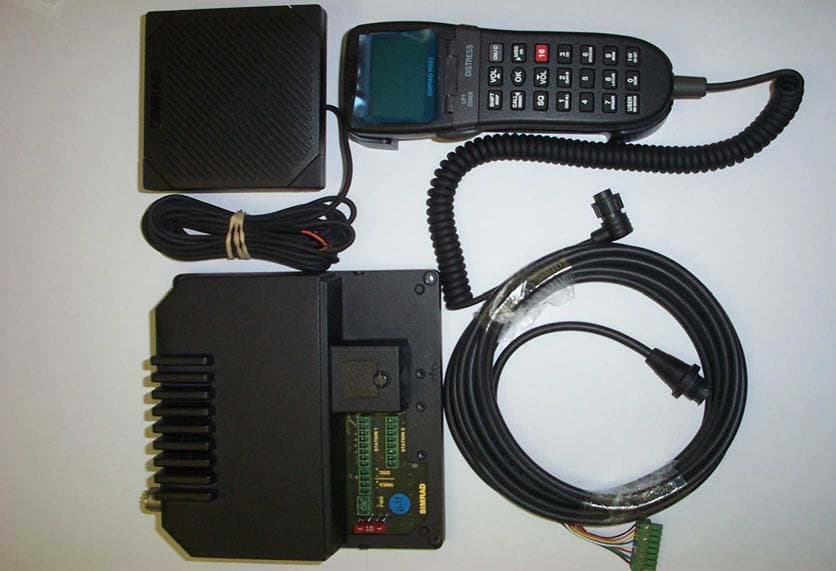
Click to zoom
Application Details
- Equipment Class
- TNB - Licensed Non-Broadcast Station Transmitter
- Date of Grant
- Oct 03, 2004
- Application Purpose
- Original Equipment
- Date of Application
- Aug 11, 2004
- Equipment Note
- VHF marine raidotelephone - DSC upgradeable
- Frequency Range
- 156.52500000 - 156.52500000
- Company
- Simrad Ltd
- Country
- United Kingdom
Documents & Files
Document Text
Text extracted from the exhibit documents filed with the FCC. Open a document above to read the original.
Users Manual
MAXIMIZING YOUR PERFORMANCE AT SEA Instruction manual III Simrad RS81/RS82 VHF Radio System MANUAL RS81/RS82 VHF IV Part no. E04572 Issue E 26/04/04 CR The technical data, information and illustrations contained in this publication were to the best of our knowledge correct at the time of going to print. We reserve the right to change specifications, equipment, installation and mainte- nance instructions without notice as part of our policy of continuous development and improvement. No part of this publication may be reproduced, stored in a retrieval system or transmitted in any form, electronic or otherwise without prior permission from Simrad Ltd. No liability can be accepted for any inaccuracies or omissions in the publication, although every care has been taken to make it as complete and accurate as possible. © 2004 Simrad Ltd Part I – INTRODUCTION 1 GENERAL 1.1 Introduction . . . . . . . . . . . . . . . . . . . . . . . . . . . . . . . . . . . . . . . . . . . .11 1.1.1 About this manual . . . . . . . . . . . . . . . . . . . . . . . . . . . . . . . . .12 1.2 Licensing . . . . . . . . . . . . . . . . . . . . . . . . . . . . . . . . . . . . . . . . . . . . . .13 1.3 MMSI number . . . . . . . . . . . . . . . . . . . . . . . . . . . . . . . . . . . . . . . . . .14 1.4 Group ID MMSI . . . . . . . . . . . . . . . . . . . . . . . . . . . . . . . . . . . . . . . . .14 1.5 ATIS number . . . . . . . . . . . . . . . . . . . . . . . . . . . . . . . . . . . . . . . . . . .14 Part II – THE RS81 VHF RADIO SYSTEM 2 INTRODUCTION 3 MAIN FUNCTIONS 3.1 General notes . . . . . . . . . . . . . . . . . . . . . . . . . . . . . . . . . . . . . . . . . . .17 3.2 Switching the radio on & off . . . . . . . . . . . . . . . . . . . . . . . . . . . . . .18 3.3 Second country modes . . . . . . . . . . . . . . . . . . . . . . . . . . . . . . . . . . .18 3.4 Changing channels . . . . . . . . . . . . . . . . . . . . . . . . . . . . . . . . . . . . . .19 3.4.1 Channel sets . . . . . . . . . . . . . . . . . . . . . . . . . . . . . . . . . . . . . .19 3.5 Volume . . . . . . . . . . . . . . . . . . . . . . . . . . . . . . . . . . . . . . . . . . . . . . . .20 3.6 Squelch . . . . . . . . . . . . . . . . . . . . . . . . . . . . . . . . . . . . . . . . . . . . . . . .20 3.7 Speaker mute . . . . . . . . . . . . . . . . . . . . . . . . . . . . . . . . . . . . . . . . . . .21 3.8 Dual Watch mode . . . . . . . . . . . . . . . . . . . . . . . . . . . . . . . . . . . . . . .21 3.9 Triple Watch or Tri-Watch mode . . . . . . . . . . . . . . . . . . . . . . . . . . .22 3.10 All scan mode . . . . . . . . . . . . . . . . . . . . . . . . . . . . . . . . . . . . . . . . .22 3.10.1 Dynamic All scan inhibit . . . . . . . . . . . . . . . . . . . . . . . . . . .23 3.11 Memory scan mode . . . . . . . . . . . . . . . . . . . . . . . . . . . . . . . . . . . . .23 3.11.1 Dynamic Memory scan delete . . . . . . . . . . . . . . . . . . . . . . .24 3.12 Adjusting backlighting . . . . . . . . . . . . . . . . . . . . . . . . . . . . . . . . . .24 3.13 Handset off cradle . . . . . . . . . . . . . . . . . . . . . . . . . . . . . . . . . . . . . .24 4 MENU MODE 4.1 Scanning . . . . . . . . . . . . . . . . . . . . . . . . . . . . . . . . . . . . . . . . . . . . . . .25 4.1.1 All scan inhibit . . . . . . . . . . . . . . . . . . . . . . . . . . . . . . . . . . . .25 4.1.2 All scan reset . . . . . . . . . . . . . . . . . . . . . . . . . . . . . . . . . . . . . .26 4.1.3 All scan show . . . . . . . . . . . . . . . . . . . . . . . . . . . . . . . . . . . . .26 4.1.4 Memory scan select . . . . . . . . . . . . . . . . . . . . . . . . . . . . . . . .26 4.1.5 Memory scan clear . . . . . . . . . . . . . . . . . . . . . . . . . . . . . . . . .27 4.1.6 Memory scan show . . . . . . . . . . . . . . . . . . . . . . . . . . . . . . . . .27 4.1.7 Scan dwell time . . . . . . . . . . . . . . . . . . . . . . . . . . . . . . . . . . . .27 4.2 Numbers . . . . . . . . . . . . . . . . . . . . . . . . . . . . . . . . . . . . . . . . . . . . . . .28 4.2.1 Ship’s MMSI . . . . . . . . . . . . . . . . . . . . . . . . . . . . . . . . . . . . . .28 4.2.2 ATIS number . . . . . . . . . . . . . . . . . . . . . . . . . . . . . . . . . . . . . .29 4.3 VHF Items . . . . . . . . . . . . . . . . . . . . . . . . . . . . . . . . . . . . . . . . . . . . .31 4.3.1 User channel . . . . . . . . . . . . . . . . . . . . . . . . . . . . . . . . . . . . . .31 4.3.2 Last used channel . . . . . . . . . . . . . . . . . . . . . . . . . . . . . . . . . .32 Instruction manual V E04572 C O N T E N T S 4.3.3 Interrupt intercom . . . . . . . . . . . . . . . . . . . . . . . . . . . . . . . . .32 4.3.4 Speaker settings . . . . . . . . . . . . . . . . . . . . . . . . . . . . . . . . . . .32 4.3.4.1 Setting up speakers . . . . . . . . . . . . . . . . . . . . . . . . . .33 4.3.4.2 Adjusting independent volumes . . . . . . . . . . . . . . .33 4.3.5 Lighting modes . . . . . . . . . . . . . . . . . . . . . . . . . . . . . . . . . . . .33 4.3.6 SimNet . . . . . . . . . . . . . . . . . . . . . . . . . . . . . . . . . . . . . . . . . . .34 4.3.6.1 Banks select . . . . . . . . . . . . . . . . . . . . . . . . . . . . . . . . .34 4.3.6.2 Device instance . . . . . . . . . . . . . . . . . . . . . . . . . . . . . .34 4.3.6.3 System instance . . . . . . . . . . . . . . . . . . . . . . . . . . . . .35 4.3.7 Serial number . . . . . . . . . . . . . . . . . . . . . . . . . . . . . . . . . . . . .35 5 MISCELLANEOUS FUNCTIONS 5.1 Selecting Weather Watch . . . . . . . . . . . . . . . . . . . . . . . . . . . . . . . . . .36 5.1.1 Weather Watch alert . . . . . . . . . . . . . . . . . . . . . . . . . . . . . . . .36 5.2 Security mode (voice scrambler) . . . . . . . . . . . . . . . . . . . . . . . . . . .37 5.3 Losing NMEA data . . . . . . . . . . . . . . . . . . . . . . . . . . . . . . . . . . . . . .37 5.4 Intercom . . . . . . . . . . . . . . . . . . . . . . . . . . . . . . . . . . . . . . . . . . . . . . .37 5.4.1 Making an intercom call .…
Text truncated - open the document above for the full version.
Users Manual
RS81/RS82 VHF 52 E04572 8 MENU MODE Menu mode is used to adjust the various settings of the radio, such as channels inhibited from scan functions, MMSI number programming and User channel selection. To enter Menu mode, press S HIFTfollowed by 9(MENU). Use the V OL▲and VOL▼keys to scroll through the menu options below: • Scanning(section 8.1) – Options related to the various scanning functions such as channel inhibit, memory scan select and scan dwell time. • Numbers(section 8.2) – Entering of ID numbers such as MMSI, Group MMSI and ATIS numbers (if applicable in country of use). • VHF Items(section 8.3) – Miscellaneous options such as selection of User channel, last used channel, interrupt inter- com, speaker settings and SimNet management. To select an option, press O K. To return to normal radio opera- tion, press O N/C. NOTEEntering Menu mode will inhibit the operation of the radio. Exit Menu mode before returning the handset to the cradle to permit normal operation. 8.1 Scanning Once the Scanning menu option has been selected (see intro- duction to section 8), use the V OL▲and VOL▼keys to scroll through the menu options below: • All scan inhibit (section 8.1.1) • All scan reset (section 8.1.2) • All scan show (section 8.1.3) • Memory scan select (section 8.1.4) • Memory scan clear (section 8.1.5) • Memory scan show (section 8.1.6) • Scan dwell time (section 8.1.7) To select an option, press O K. To return to the main menu, press O N/C. 8.1.1 All scan inhibit If the radio is repeatedly locking onto a busy channel when scanning, this channel can be inhibited, i.e. excluded from the scan cycle. Instruction manual 53 E04572 Use the VOL▲and VOL▼keys to select another option, or O N/Cto return to the upper menu level. 8.1.3 All scan show This function will display all inhibited channels. From the Scanning menu select “ALL SCAN SHOW” and press O K. The display will change to “SHOWING CHANNELS” and display all inhibited channels in sequence. Press the V OL▲and VOL▼keys to select a further option, or O N/Cto return to the main menu. 8.1.4 Memory scan select This function selects the channels to be used in the Memory scan cycle (see section 7.9). Repeat the above procedure to enable or inhibit further chan- nels, or use the V OL▲and VOL▼keys to select another menu option. To exit this menu level, press O N/C. 8.1.2 All scan reset To reset all inhibited channels select “ALL SCAN RESET” from the Scanning menu and press O K. The display will show “CHANNELS RESET” (Fig 8.2). From the Scanning menu select “ALL SCAN INHIBIT” and press O K. Enter the relevant channel number using the numeric keypad. The display will show the channel number and its cur- rent status – “ALL SCAN” for enabled, or “ALL SCAN INHIB- ITED” for excluded channels (Fig 8.1). Use the O Kkey to change the channel’s status. 65 ALL SCANAA INH IB ITEDB INT Fig 8.1 - Selected channel inhibited from scan CHANNELSSS RESETEDBBB Fig 8.2 - All inhibited channels reset RS81/RS82 VHF 54 E04572 Press the VOL▲and VOL▼keys to select another Scanning menu option, or press O N/Cto return to the main menu. From the Scanning menu choose “MEM SCAN SELECT” and press O K. Enter the relevant channel number using the numeric keypad. The display will show the channel number and its memory status – “MEM SCAN” if it is not currently selected for memory scan, or “MEM SCAN ENABLED” if it is already selected (Fig 8.3). Use the O Kkey, to change the channel’s status – i.e. if it is not selected, pressing O Kwill add it to the Memory scan cycle and vice versa. Repeat the above procedure to select or deselect further chan- nels. When finished, press O N/Cto return to the main menu, or use the V OL▲and VOL▼keys to select another menu option. NOTENorth American users– Only one Weather channel can be stored in the memory scan; if another one is selected, it will override the existing channel. The Weather channel is not scanned as part of the memory scan sequence, it is in fact used by the Weather Watch function (see section 11.1). 8.1.5 Memory scan clear Memory scan clear will remove all previously selected chan- nels. To clear all channels select “MEM SCAN CLEAR” from the Scanning menu, then press O K– the display will change to show “CHANNELS CLEARED” (Fig 8.4). 65 MEM SCANAA ENABLEDBB INT 65 MEM SCANAA INT Fig 8.3 - Selecting channel for Memory scan CHANNEL CURRENTLY NOT SELECTEDCHANNEL ALREADY SELECTED CHANNELSSS CLEAREDBBB Fig 8.4 - Clearing all previously selected channels Instruction manual 55 E04572 8.1.6 Memory scan show This function displays all channels selected for Memory scan. From the Scanning menu select “MEMORY SCAN SHOW” and press O K. The display will change to “SHOWING CHANNELS” and display all enabled channels in sequence. Press the V OL▼or VOL▲key to select another Scanning menu option, or O N/Cto return to the main menu. 8.1.7 Scan dwell time This function is used to select the amount of time the RS82 remains on a channel, after it has locked onto it during a scan- ning function (All scan or Memory scan) and the signal is lost. From the Scanning menu (section 8.1) select “SCAN DWELL TIME XX” (where “XX” denotes the current dwell time in sec- onds), then press O K(Fig 8.5). The default time is “0”, meaning that the scan will continue as soon as the signal is lost. There are 11 levels from 0–10 seconds. Use the numeric keys to enter the scan dwell time and press O K to select – the display will show “DWELL TIME XX SECONDS”. Press the V OL▲or VOL▼key to select another Scanning menu option, or O N/Cto return to the main menu. 8.2 Numbers The Numbers menu is used for entering ID numbers such as MMSI, Group MMSI and ATIS (if applicable in country of use). Once the Numbers menu option has been selected (see intro- duction to section 8), the V OL▲and VOL▼keys to scroll through the menu options below: • Ship’s MMSI(section 8.2.1) • Group MMSI(section 8.2.2) • ATIS number (section 8.2.3) NOTEThe ATIS number option will only be shown if the radio is AT…
Text truncated - open the document above for the full version.
Users Manual
The AHS81 and AHS82 have been designed with simple opera- tion in mind for ease of use, even in installations that have one station of each type. The handsets are fully waterproof and designed for all environments from the navigation station to the open cockpit. 1.1.1 About this manual This manual combines operating and installation information on both the RS81 and RS82 and is divided into four main parts. As the handsets have differing layouts and functions are accessed in different ways, we recommend that you familiarise yourself with the information pertaining to the product that you have purchased prior to installation or use. This will facili- tate full understanding of the many operating features and ensure straightforward installation. Thank you for choosing Simrad! If you are pleased with your VHF radio, we hope you will be interested in our range of marine electronic equipment, which is manufactured to the same high standards as the RS81/RS82. Please contact your nearest Simrad agent for a catalogue show- ing our increasing range of high-tech navigational instruments, GPS, Autopilots, Radar, Echosounders, Chartplotters and VHF radio sets. Simrad operates a policy of continual development and reserve the right to alter and improve the specification of their products without notice. 1.2 Radio Frequency Exposure Guidelines (US only) To meet FCC (Federal Communications Commission) rules on Radio Frequency Exposure, it is recommended that the VHF antenna is mounted at least 3 m (10 ft) away from any area accessible to any personnel onboard. If this distance is achieved by vertical separation, the antenna must be at least 5 m (16.5 ft) above deck to allow for the height of an adult. This guideline applies only to antennae not exceeding 9dBi gain. In order to comply with the FCC’s Maximum Permissible Expo- sure (MPE), the radio operator is responsible for ensuring that there is no personnel within this range before transmitting. WARNINGFailure to observe these recommendations may expose those within the MPE radius of 3 m (10 ft) to RF absorption levels that exceed the FCC safe limits. RS81/RS82 VHF 12 E04572 Issue 1.0 RS81/RS82 VHF 108 E04572 13.4 Channel Frequencies NOTECh 0 will only be made available in the UK to Coastguard users with written authorisation. Channel 70 is the designated Digital Selected Calling(DSC) channel and may not be used for voice transmissions.
External Photos
Fig 1: RS81 system, comprising RS80B transceiver, AHS81 and EXBH05 cable Fig 2: RS82 system, comprising RS80B transceiver, AHS82, LS80 and EXAH05 cable Fig 3: RS80B Transceiver – Top view Fig 4: RS80B Transceiver – Side view Fig 5: RS80 Transceiver – Rear view Fig 6: AHS81 active handset – Top view Fig 7: AHS81 active handset – Side view Fig 8: AHS81 active handset – Bottom view with cradle Fig 9: AHS82 DSC enabled handset – Top view Fig 10: AHS82 DSC enabled handset – Side view Fig 11: AHS82 DSC enabled handset – Bottom view with cradle Fig 12: LS80 loudspeaker – Top view Fig 13: LS80 loudspeaker – Side view Fig 14: LS80 loudspeaker – Bottom view
ID Label/Location Info
Fig 1: FCC Identity Label Fig 1: Position of FCC ID label on base of unit.
Internal Photos
Fig 1: Interior of RS80B showing RF PCB location Fig 2: Reverse of RS80B RF PCB Fig 3: Interior of RS80B showing RF screen Fig 4: Interior of RS80B showing control PCB Fig 5: Reverse of RS80 Control PCB Fig 6: View of RS80B showing Connectors For Simrad use only Normally covered Power Connector NMEA0183 position input Handset Connectors SimNet/NMEA2000 connectors
Internal Photos
Fig 1: Exterior view of AHS81 Handset Fig 2: Interior view of AHS81 handset Fig 3: Rear view of AHS81 PCB
Test Report
NAVIGATION AND COMMUNICATION SYSTEMS REPORT FORM FOR TESTING TO CFR47 part 80 Test Report Number: TAR020 Stations in the Maritime Service CONTENTS Page Section 1Introduction......................................................2 Section 2Test Technical Details.......................................4 Section 3Transmitter Test Results....................................5 Section 4Equipment List............................................15 Section 5Measurement Scan Results.................................16 Section 6Photos of Test Measurement Setup..................23 2 Simrad Ltd Star Lane Margate Kent CT9 4NP Simrad Ltd complies with the accreditation criteria requirements of the quality standards, BS EN ISO 9001:1994. The accreditation covers the quality system of the EMC test department as well as the, design,manufacture, distribution, aftersales, marketing and support of communications and marine electronics for the leisure, commercial and military markets, as described in the certificate of approval bearing the certificate number AJA02/4543 and granted on 28th January 2002. All testing was carried out within the EMC test department of Simrad Ltd, to the requirements of CFR47 Part80 Testing carried out by: Kevin Heath Report checked by: David Sheekey Date:08/03/2004 3 SECTION 4 TEST TECHNICAL DETAILS Test Unit = RS81 Serial Number = TA unit 001 Additional Parts =AHS82DSC enabled handset Nominal Voltage = 12.0 Volts Maximum Voltage = 15.6 Volts Minimum Voltage = 10.8 Volts Nominal Temperature = 20°C Maximum Temperature = 55°C Minimum Temperature = -15°C Channel 16 = 156.800MHz Upper Frequency = 163.000MHz Lower Frequency = 155.000MHz Second Receiver Frequency = 157.525MHz Channel Spacing = 25kHz First IF Main Rx = 21.4MHz Second IF Main Rx = 450kHz First IF 2nd Rx = 17.9kHz Second IF 2nd Rx = 450kHz Rated Audio Power = 2.0 Watts( external speaker ) N/A( handset earphone ) Rated Audio Load = 4 Ohms( external speaker ) N/A( handset earphone ) Tested configuration consisted of one RS80B transceiver, with an AHS81 handset, an AHS82 DSC enabled handset and an LS80 external loudspeaker. 4 SECTION 3 Transmitter RF Output Power conducted to the antenna Specification: CFR47 2.1046(a) Test Equipment Used: Measurement Procedure TEST CONDITIONSOUTPUT POWER (Watts) on 25W setting Pass/Fail 155.000MHz 156.800MHz 163.000MHz Tnom (20°C) Vnom (12V) 22.421.921.0 Pass Tmax (55°C) Vmin (10.8V) 21.119.417.1 Pass Vmax(15.6V) 22.921.020.8 Pass Tmin (-15°C) Vmin (10.8V) 19.720.219.1 Pass Vmax(15.6V) 19.920.421.3 Pass TEST CONDITIONSOUTPUT POWER (Watts) on 1W setting Pass/Fail 155.000MHz 156.800MHz 163.000MHz Tnom (20°C) Vnom (12V) 0.730.730.70 Pass Tmax (55°C) Vmin (10.8V) 0.860.640.78 Pass Vmax(15.6V) 0.850.650.77 Pass Tmin (-15°C) Vmin (10.8V) 0.620.650.63 Pass Vmax(15.6V) 0.630.640.60 Pass Complies? Yes The EUT is connected to a regulated power supply set to the nominal supply voltage. The antenna socket is connected to a radiocommunications test set. This equipment is used for measurement of RF output power, transmitter frequency and modulation levels. The Tranmitter power is measured on channel 16 and the highest and lowest frequencies the transceiver is rated for. Measurment are made at the nominal supply voltage, at +30%, -10% of the supply voltage and at the extremes of temperature. Note: Channels 02, 04, 60 and 62 are barred from operation. Channels 13 and 67 are low power only. 6, 9, 11, 20, 21 Radio Communications Test Set EUT Stabilized Power Supply 5 SECTION 3 Transmitter Frequency Error Specification: CFR47 2.1055(a) Test Equipment Used: 6, 9, 11, 20, 21, 22 Measurement Procedure Test Frequency: 156.800MHz TemperatureLimitFrequency(MHz)Pass/Fail °C High PowerLow Power -201.5kHz156.799530 156.799530-0.470-0.470 Pass -101.5kHz156.799830 156.799830-0.170-0.170 Pass 01.5kHz156.799940 156.799940-0.060-0.060 Pass 101.5kHz156.799880 156.799880-0.120-0.120 Pass 201.5kHz156.800050 156.8000500.0500.050 Pass 301.5kHz156.799550 156.799550-0.450-0.450 Pass 401.5kHz156.799410 156.799410-0.590-0.590 Pass 501.5kHz156.799490 156.799490-0.510-0.510 Pass 601.5kHz156.799610 156.799610-0.390-0.390 Pass Limits: Maximum permissible frequency error +-1.5kHz Complies:Yes The EUT is connected to a regulated power supply set to the nominal supply voltage. The antenna socket is connected to a radiocommunications test set. This equipment is used for measurement of RF output power, transmitter frequency and modulation levels. The Transceiver was placed in a temperature controlled environment and allowed to settle for 30 minutes at each test temperature before a measurement was made. Tests were carried out on channel 16 at both high and low powers. As there was no discernible change in frequency error with supply voltage these results have not been recorded Freq Error - High Power Freq Error - Low Power Radio Communications Test Set EUT Stabilised Power Supply 6 Transmitter Frequency Error -2.0kHz-1.5kHz-1.0kHz -.5kHz .0kHz.5kHz 1.0kHz1.5kHz2.0kHz -20-10 0 10203040506070 ° C Freq Error - Low Power Freq Error - High Power SECTION 3 Transmitter Audio Frequncy Response Specification: CFR47 2.1047(a) Test Equipment Used: Measurement Procedure Modulation Frequency Input LevelLimitMaximum Deviation (kHz)Pass/Fail (Hz)High PowerLow Power 10020db 3kHz5.0kHz1.921.93 Pass 20020db 3kHz5.0kHz4.484.61 Pass 30020db 3kHz5.0kHz4.544.61 Pass 40020db 3kHz5.0kHz4.524.60 Pass 50020db 3kHz5.0kHz4.484.53 Pass 100020db 3kHz5.0kHz3.713.80 Pass 150020db 3kHz5.0kHz3.503.50 Pass 200020db 3kHz5.0kHz4.004.06 Pass 250020db 3kHz5.0kHz3.903.96 Pass 300020db 3kHz5.0kHz3.403.43 Pass Modulation Frequency Input LevelLimitMax Deviatio nPass/Fail 30003kHz3.553.550 Pass 31003kHz3.553.410 Pass 40003kHz3.552.100 Pass 50003kHz3.551.210 Pass 60003kHz1.5kHz0.724 Pass 80003kHz.77kHz0.321 Pass 100003kHz.46kHz0.144 Pass 120003kHz.30kHz0.034 Pass 150003kHz.18kHz0.012 Pass 200003kHz.09kHz0.006 Pass 250003kHz.05kHz0.006 Pass Limits: Maximum permissible frequency deviation le…
Text truncated - open the document above for the full version.
Contact Information
Applicant
David C Sheekey(Product Manager)
Technical Contact
Simrad LtdDavid C Sheekey
[email protected]+44 (0)1843 290290
Star Lane · Margate, Kent · United Kingdom
Non-Technical Contact
Simrad LtdDavid C Sheekey
[email protected]+44 (0)1843 290290
Technical Specifications
| # | Rule Parts | Frequency Range | Power Output | Emission | Tolerance |
|---|---|---|---|---|---|
| 2 | 8 | 156.525 MHz - 156.525 MHz | 25 W | 16K0G2B | 10 ppm |
Other Applications from Simrad Ltd
QYSSA50
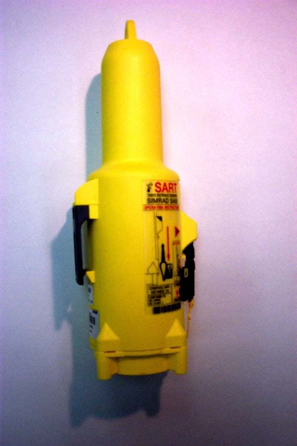
Apr 21, 2005SA50 SART
Equipment Class
SRT - Radar Transponder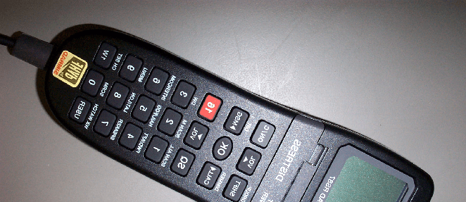
QYSRS87
Apr 27, 2003RS87 VHF Marine Radiotelephone with Class D DSC
Equipment Class
TNB - Licensed Non-Broadcast Station Transmitter