QYSRS87RS87 VHF Marine Radiotelephone with Class D DSC
Simrad Ltd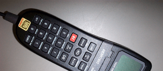
Click to zoom
Application Details
- Equipment Class
- TNB - Licensed Non-Broadcast Station Transmitter
- Date of Grant
- Apr 27, 2003
- Application Purpose
- Original Equipment
- Date of Application
- Mar 09, 2003
- Equipment Note
- RS87 VHF Marine Radiotelephone with Class D DSC
- Frequency Range
- 155.00000000 - 163.00000000
- Company
- Simrad Ltd
- Country
- United Kingdom
Documents & Files
Document Text
Text extracted from the exhibit documents filed with the FCC. Open a document above to read the original.
Users Manual
ALWAYS AT THE FOREFRONT OF TECHNOLOGY Instruction Manual III Simrad RS87 VHF Radio System MANUAL RS87 VHF IV Part No. E04297 Issue 1.1 05/03/03 MDL The technical data, information and illustrations contained in this publication were to the best of our knowledge correct at the time of going to print. We reserve the right to change specifications, equipment, installation and maintenance instructions without notice as part of our policy of continuous development and improvement. No part of this publication may be reproduced, stored in a retrieval system or transmitted in any form, electronic or otherwise without prior permission from Simrad Ltd. No liability can be accepted for any inaccuracies or omissions in the publication, although every care has been taken to make it as com- plete and accurate as possible. ©2003 Simrad Ltd CONTENTS 1. GENERAL 1.1Introduction . . . . . . . . . . . . . . . . . . . . . . . . . . . . . . . . . . . . . . 8 1.2The Simrad integrated system . . . . . . . . . . . . . . . . . . . . . . . 9 1.3Licensing . . . . . . . . . . . . . . . . . . . . . . . . . . . . . . . . . . . . . . . . 10 1.4Entering MMSI numbers . . . . . . . . . . . . . . . . . . . . . . . . . . . . 11 1.5Group ID MMSI . . . . . . . . . . . . . . . . . . . . . . . . . . . . . . . . . . . 11 2. MAIN FUNCTIONS 2.1General notes . . . . . . . . . . . . . . . . . . . . . . . . . . . . . . . . . . . . . 12 2.2Switching on & Second Country mode . . . . . . . . . . . . . . . . 12 2.3Changing channels . . . . . . . . . . . . . . . . . . . . . . . . . . . . . . . . 13 2.3.1 Channel Sets . . . . . . . . . . . . . . . . . . . . . . . . . . . . . . . . . 14 2.4Volume adjustment . . . . . . . . . . . . . . . . . . . . . . . . . . . . . . . . 15 2.5Squelch adjustment . . . . . . . . . . . . . . . . . . . . . . . . . . . . . . . . 15 2.6Dual Watch mode . . . . . . . . . . . . . . . . . . . . . . . . . . . . . . . . . 15 2.7Tri-Watch mode . . . . . . . . . . . . . . . . . . . . . . . . . . . . . . . . . . . 16 2.8All Scan mode . . . . . . . . . . . . . . . . . . . . . . . . . . . . . . . . . . . . 17 2.8.1 Dynamic All Scan Inhibit . . . . . . . . . . . . . . . . . . . . . . 17 2.9Memory Scan mode . . . . . . . . . . . . . . . . . . . . . . . . . . . . . . . . 18 2.9.1 Dynamic Memory Scan Delete . . . . . . . . . . . . . . . . . . 18 2.10 Adjusting backlighting . . . . . . . . . . . . . . . . . . . . . . . . . . . . . 19 2.11 Handset off cradle . . . . . . . . . . . . . . . . . . . . . . . . . . . . . . . . . 19 3. MENU MODE 3.1Scanning . . . . . . . . . . . . . . . . . . . . . . . . . . . . . . . . . . . . . . . . . 20 3.1.1 All Scan inhibit . . . . . . . . . . . . . . . . . . . . . . . . . . . . . . . 21 3.1.2 All Scan reset . . . . . . . . . . . . . . . . . . . . . . . . . . . . . . . . 21 3.1.3 All Scan show . . . . . . . . . . . . . . . . . . . . . . . . . . . . . . . . 22 3.1.4 Memory Scan select . . . . . . . . . . . . . . . . . . . . . . . . . . . 22 3.1.5 Memory Scan clear . . . . . . . . . . . . . . . . . . . . . . . . . . . 23 3.1.6 Memory Scan show . . . . . . . . . . . . . . . . . . . . . . . . . . . 23 3.1.7 Scan dwell time . . . . . . . . . . . . . . . . . . . . . . . . . . . . . . 23 3.2Numbers . . . . . . . . . . . . . . . . . . . . . . . . . . . . . . . . . . . . . . . . . 24 3.2.1 Ship’s MMSI . . . . . . . . . . . . . . . . . . . . . . . . . . . . . . . . . 24 3.2.2 ATIS number . . . . . . . . . . . . . . . . . . . . . . . . . . . . . . . . 25 3.2.3 Group MMSI . . . . . . . . . . . . . . . . . . . . . . . . . . . . . . . . 26 3.3VHF items . . . . . . . . . . . . . . . . . . . . . . . . . . . . . . . . . . . . . . . 27 3.3.1 User channel . . . . . . . . . . . . . . . . . . . . . . . . . . . . . . . . . 27 3.3.2 Position view . . . . . . . . . . . . . . . . . . . . . . . . . . . . . . . . 28 3.3.3 Last used channel . . . . . . . . . . . . . . . . . . . . . . . . . . . . 28 3.3.4 Interrupt intercom . . . . . . . . . . . . . . . . . . . . . . . . . . . . 29 3.3.5 Auxiliary audio . . . . . . . . . . . . . . . . . . . . . . . . . . . . . . 29 3.3.6 Speaker settings . . . . . . . . . . . . . . . . . . . . . . . . . . . . . . 30 Instruction Manual V CONTENTS ctd - 4. DSC FUNCTIONS 4.1General . . . . . . . . . . . . . . . . . . . . . . . . . . . . . . . . . . . . . . . . . . 31 4.2Making a call . . . . . . . . . . . . . . . . . . . . . . . . . . . . . . . . . . . . . 31 4.2.1 Individual Routine call . . . . . . . . . . . . . . . . . . . . . . . . 31 4.2.2 Public Correspondence call . . . . . . . . . . . . . . . . . . . . . 32 4.2.3 All Ships Safety call . . . . . . . . . . . . . . . . . . . . . . . . . . . 34 4.2.4 All Ships Urgency call . . . . . . . . . . . . . . . . . . . . . . . . . 34 4.2.5 Group call . . . . . . . . . . . . . . . . . . . . . . . . . . . . . . . . . . . 35 4.2.6 Distress Alert call . . . . . . . . . . . . . . . . . . . . . . . . . . . . . 35 4.3Receiving a call . . . . . . . . . . . . . . . . . . . . . . . . . . . . . . . . . . . 37 4.3.1 Individual Routine call . . . . . . . . . . . . . . . . . . . . . . . . 37 4.3.2 Public Correspondence call . . . . . . . . . . . . . . . . . . . . . 38 4.3.3 All Ships Safety call . . . . . . . . . . . . . . . . . . . . . . . . . . . 39 4.3.4 All Ships Urgency call . . . . . . . . . . . . . . . . . . . . . . . . . 39 4.3.5 Group call . . . . . . . . . . . . . . . . . . . . . . . . . . . . . . . . . . . 40 4.3.6 Distress Alert call . . . . . . . . . . . . . . . . . . . . . . . . . . . . . 41 4.3.7 Distress Alert acknowledgement . . . . . . . . . . . . . . . . 42 4.3.8 Distress Relay call . . . . . . . . . . . . . . . . . . . . . . . . . . . . 43 4.4Viewing the Call Log . . . . . . . . . . . . . . . . . . . . . . . . . . . . . . . 44 4.5Position over 4 hours old . . . . . . . . . . . . . . . . . . . . . . . . . . . 45 5. THE DIRECTORY 5.1Switching between the directories . . . . . . . . . . . . . . . . . . . . 46 5.2Viewing the directory . . . . . . .…
Text truncated - open the document above for the full version.
External Photos
RS87 EXTERNAL PHOTOGRAPHS Fig 1: View of System components supplied as standard Fig 2: External view of transceiver unit, showing connectors Fig 3: External view of handset.
ID Label/Location Info
RS87 IDENTITY LABEL AND POSITION Fig 1: Layout of FCC identity label Fig 2: Photograph showing position of label on unit.
Internal Photos
RS87 TRANSCEIVER - INTERIOR PICTURES Fig 1: Interior View of Transceiver with Expansion PCB fitted Fig 2: Interior View of Transceiver without Expansion PCB fitted Fig 3: Interior View of Transceiver showing RF PCB only Fig 4: RF PCB – Component Side Fig 5: Control PCB – Component Side Fig 6: Expansion PCB – Component Side
Test Report
NAVIGATION AND COMMUNICATION SYSTEMS REPORT FOR TESTING RS87 TO EN 801 843-1 REPORT NUMBER: EMC047 ELECTROMAGNETIC COMPATIBILITY AND RADIO SPECTRUM MATTERS (ERM) ELECTROMAGNETIC COMPATIBILITY (EMC) FOR RADIOTELEPHONE TRANSMITTERS AND RECEIVERS FOR THE MARITIME MOBILE SERVICE OPERATING IN THE VHF BANDS Simrad Ltd RS87 Test Report to EN 301 843-2 CONTENTS Page Section 1Introduction.....................................................................3 Section 2Product...........................................................................4 Section 3Test Schedule.................................................................4 Section 5Summary of Tests............................................................6 Section 6 Results........................................................................... 7 Section 7Test Equipment List........................................................13 Section 8Measurement Scan Results...............................................14 Section 9Photographs of EUT..........................................................20 Page 2 Simrad Ltd RS87 Test Report to EN 301 843-2 SECTION 1 INTRODUCTION This report contains the results of tests performed on the product RS87 VHF radio with DSC, on this premises of : Simrad Ltd Star Lane Margate Kent Simrad Ltd complies with the accreditation criteria requirements of the quality standards, BS EN ISO 9001:1994. The accreditation covers the quality system of the EMC test department as well as the, design, manufacture, distribution, aftersales, marketing and support of communications and marine electronics for the leisure, commercial and military markets, as described in the certificate of approval bearing the certificate number AJA02/4543 and was granted on 28th January 2002. All testing was carried out within the EMC test department of Simrad Ltd, to the requirements of EN 801 843-1 V1.1.1(2001-02). Testing carried out by:.............................................. Report checked by:.............................................. Date:...................... Page 3 Simrad Ltd RS87 Test Report to EN 301 843-2 SECTION 2 PRODUCT A sample of the following product was submitted for testing: Maritime Integrated VHF/DSC Radiotelephone with ATIS Manufacture:Simrad Ltd Parts of Product:RS87; Transceiver Unit with DSC controller & ATIS. Handsets, Speakers and Hailer's. Serial Number:TA / EMC Unit 1 Software Release:Issue 1 Particulars:DSC Class D SECTION 3 TEST SCHEDULE All tests were carried out within the EMC department at Simrad Ltd. The sample unit was tested between the following dates: 13th January 2003 - 1st February 2003. The RS87 VHF radio with DSC & ATIS, is intended for use in the following application area: MARINE COMMUNICATIONS EQUIPMENT; and was tested to ETSI EN 801 843-1 V1.1.1(2001-02). The following tests shown below were carried out on a sample of the RS87 VHF radio with DSC & ATIS Test ClauseDescription of TestDate of Test 8.1.2.1Radiated Emissions (150kHz-30Mhz)30/1/03-1/2/03 8.2DC Power Ports01/02/2003 9.1RF Electromagnetic Field (80Mhz-1Ghz)15-31/1/2003 9.2Electrostatic Discharge01/02/2003 9.3Fast Transient01/02/2003 9.4Conducted disturbances induced by RF fields (150Khz-80Mhz)01/02/2003 9.6Power Supply Failure01/02/2003 Exempt from Testing Test ClauseDescription of TestReason This test is covered by EN 301 025 V1.1.1 (1998-08), See test report for RS87 VHF radio with DSC & ATIS to EN 301 025. This test is required on AC power input ports only, the RS87 requires a 12v DC input only, therefore is exempt. This test is required on AC power input ports only, the RS87 requires a 12v DC input only, therefore is exempt. Radiated Emissions (30Mhz-1Ghz) Power Supply Short Term Variation Surge 8.1.2.2 9.5 9.7 Page 4 Simrad Ltd RS87 Test Report to EN 301 843-2 SECTION 4 TEST TECHNICAL DETAILS Test Unit = RS87 VHF Radio with DSC & ATIS. Serial Number = TA / EMC UNIT 2 Additional Parts = Telephone handsets x 4 / External Speakers x 2 / Hailers x 2 Nominal Voltage = 12.0 Volts Upper Frequency = 162.975MHz Lower Frequency = 155.025MHz Second Receiver Frequency = 156.525MHz Channel Spacing = 25.0kHz First IF Main Rx = 21.4MHz Second IF Main Rx = 455.0kHz First IF 2nd Rx = 17.9MHz Second IF 2nd Rx = 455.0kHz Rated Audio Power = 2.0 Watts( external speaker ) 2 mW( handset earphone ) Rated Audio Load = 4 Ohms( external speaker ) 228 Ohms( handset earphone ) Page 5 Simrad Ltd RS87 Test Report to EN 301 843-2 SECTION 5 SUMMARY OF TEST RESULTS Clause NoDescription of TestComplies? 8.2 Radiated Emissions (150kHz-30Mhz)Yes 8.2 Radiated Emissions (30Mhz-1Ghz)Yes* 8.3 DC power in/outYes 9.2 RF electromagnetic field (80Mhz-1Ghz)Yes 9.3 Electrostatic DischargeYes 9.4 Fast TransientsYes 9.5 Radio Frequency - Common Mode Yes 9.6.1 Power Supply Short Term VariationsYes* 9.6.2 Power Supply FailureYes 9.7 SurgeYes* Note: * = See Section 3 (exempt from testing) The test sample of RS87 VHF radio with DSC & ATIS has successfully passed a series of tests to EN 801 843-1 V1.1.1(2001-02), which indicate its compliance with the EMC criteria of ETSI EN 801 843-1 V1.1.1(2001-02). Page 6 Simrad Ltd RS87 Test Report to EN 301 843-2 SECTION 6 RADIATED EMISSIONSClause :8.2 Definition:This test assesses the ability of the EUT to limit unwanted emissions from the enclosure. Product:RS87; Transceiver Unit with DSC controller & ATIS. Handsets, Speakers and Hailer's. Method:As per EN 801 843, clause 8.1.2.1. Results: General conditions: Date of test:15th to 31st January 2003 Temperature:Tnom (20°C) Rated power: 25 Watts Supply:Vnom (12V) Channel tested:156.800MHz To identify any potential emissions the EUT was placed inside a anechoic chamber, connected to 12v dc power supply. With the radio placed in receive and (25w) transmit mode, a measurement scan was then carried out in all axis under software control, and the emissions compared against the limits as defined in table 1, Clause 8.2.3 EN 801 843 V1.1.1. Results from this test can be found at sec…
Text truncated - open the document above for the full version.
Test Report
NAVIGATION AND COMMUNICATION SYSTEMS REPORT FORM FOR TESTING TO CFR47 part 80 Test Report Number: TAR015 Stations in the Maritime Service CONTENTS Page Section 1Introduction.............................................................2 Section 2Test Technical Details....................................................4 Section 3Transmitter Test Results.......................................................5 Section 4Measurement Scan Results..............................................15 2 Simrad Ltd Star Lane Margate Kent CT9 4NP Simrad Ltd complies with the accreditation criteria requirements of the quality standards, BS EN ISO 9001:1994. The accreditation covers the quality system of the EMC test department as well as the, design,manufacture, distribution, aftersales, marketing and support of communications and marine electronics for the leisure, commercial and military markets, as described in the certificate of approval bearing the certificate number AJA02/4543 and granted on 28th January 2002. All testing was carried out within the EMC test department of Simrad Ltd, to the requirements of CFR47 Part80 Testing carried out by: Stefan Kennedy Report checked by: David Sheekey Date:15/03/2003 3 SECTION 4 TEST TECHNICAL DETAILS Test Unit = RS87 Serial Number = Additional Parts =EXB80 Nominal Voltage = 12.0 Volts Maximum Voltage = 15.6 Volts Minimum Voltage = 10.8 Volts Nominal Temperature = 20°C Maximum Temperature = 55°C Minimum Temperature = -15°C Channel 16 = 156.800MHz Upper Frequency = 163.000MHz Lower Frequency = 155.000MHz Second Receiver Frequency = 157.525MHz Channel Spacing = 25kHz First IF Main Rx = 21.4MHz Second IF Main Rx = 450kHz First IF 2nd Rx = 17.9kHz Second IF 2nd Rx = 450kHz Rated Audio Power = 2.0 Watts( external speaker ) N/A( handset earphone ) Rated Audio Load = 2.0 Watts( external speaker ) N/A( handset earphone ) 4 SECTION 3Transmitter RF Output Power conducted to the antenna Specification: CFR47 2.1046(a) Test Equipment Used: Measurement Procedure TEST CONDITIONSOUTPUT POWER (Watts) on 25W setting Pass/Fail 155.000MHz156.800MHz163.000MHz Tnom (°C) Vnom (12V) 22.722.520.9Pass Tmax (°C) Vmin (10.8V) 20.318.015.0Pass Vmax(15.6V) 22.423.321.9Pass Tmin (°C) Vmin (10.8V) 22.322.119.1Pass Vmax(15.6V) 22.721.921.2Pass TEST CONDITIONSOUTPUT POWER (Watts) on 1W setting Pass/Fail 155.000MHz156.800MHz163.000MHz Tnom (°C) Vnom (12V) 0.78500.78200.7150Pass Tmax (°C) Vmin (10.8V) 0.8650.8670.771Pass Vmax(15.6V) 0.8570.8490.759Pass Tmin (°C) Vmin (10.8V) 0.6710.6900.668Pass Vmax(15.6V) 0.6870.6870.631Pass Complies? Yes The EUT is connected to a regulated power supply set to the nominal supply voltage. The antenna socket is connected to a radiocommunications test set. This equipment is used for measurement of RF output power, transmitter frequency and modulation levels. The Tranmitter power is measured on channel 16 and the highest and lowest frequencies the transceiver is rated for. Measurment are made at the nominal supply voltage, at +30%, -10% of the supply voltage and at the extremes of temperature. Note: Channels 02, 04, 60 and 62 are barred from operation. Channels 13 and 67 are low power only. 6, 9, 11, 20, 21 Radio Communications Test Set EUT Stabilized Power Supply 5 SECTION 3Transmitter Frequency Error Specification: CFR47 2.1055(a) Test Equipment Used: 6, 9, 11, 20, 21, 22 Measurement Procedure Test Frequency: 156.800MHz TemperatureLimitFrequency(MHz)Pass/Fail C High PowerLow Power -201.5kHz156.799530156.799530-0.470-0.470Pass -101.5kHz156.799830156.799830-0.170-0.170Pass 01.5kHz156.799940156.799940-0.060-0.060Pass 101.5kHz156.799880156.799880-0.120-0.120Pass 201.5kHz156.800050156.8000500.0500.050Pass 301.5kHz156.799550156.799550-0.450-0.450Pass 401.5kHz156.799410156.799410-0.590-0.590Pass 501.5kHz156.799490156.799490-0.510-0.510Pass 601.5kHz156.799610156.799610-0.390-0.390Pass Limits: Maximum permissible frequency error +-1.5kHz Complies: Yes The EUT is connected to a regulated power supply set to the nominal supply voltage. The antenna socket is connected to a radiocommunications test set. This equipment is used for measurement of RF output power, transmitter frequency and modulation levels. The Transceiver was placed in a temperature controlled environment and allowed to settle for 30 minutes at each test temperature before a measurement was made. Tests were carried out on channel 16 at both high and low powers. As there was no discernible change in frequency error with supply voltage these results have not been recorded Freq Error - High Power Freq Error - Low Power Radio Communications Test Set EUT Stabilised Power Supply 6 Transmitter Frequency Error -2.0kHz -1.5kHz -1.0kHz -.5kHz .0kHz .5kHz 1.0kHz 1.5kHz 2.0kHz -20-10010203040506070 C Freq Error - Low PowerFreq Error - High Power SECTION 3Transmitter Audio Frequncy Response Specification: CFR47 2.1047(a) Test Equipment Used: Measurement Procedure Modulation Frequency Input LevelLimitMaximum Deviation (kHz)Pass/Fail (Hz)High PowerLow Power 10020db 3kHz5.0kHz2.072.06Pass 20020db 3kHz5.0kHz4.584.58Pass 30020db 3kHz5.0kHz4.654.69Pass 40020db 3kHz5.0kHz4.654.68Pass 50020db 3kHz5.0kHz4.494.57Pass 100020db 3kHz5.0kHz3.693.79Pass 150020db 3kHz5.0kHz3.443.44Pass 200020db 3kHz5.0kHz4.034.07Pass 250020db 3kHz5.0kHz3.923.95Pass 300020db 3kHz5.0kHz3.363.41Pass Modulation Frequency Input LevelLimitMax DeviationPass/Fail 30003kHz3.533.530Pass 31003kHz3.533.380Pass 40003kHz3.532.060Pass 50003kHz3.531.180Pass 60003kHz1.5kHz0.702Pass 80003kHz.77kHz0.321Pass 100003kHz.46kHz0.175Pass 120003kHz.30kHz0.080Pass 150003kHz.18kHz0.048Pass 200003kHz.09kHz0.035Pass 250003kHz.05kHz0.035Pass Limits: Maximum permissible frequency deviation less than <5 khz Complies: Yes 6, 9, 20, 21, 22 The EUT is connected to a regulated power supply set to the nominal supply voltage. The antenna socket is connected to a radiocommunications test set. This equipment is used for measurement of RF output power, transmitter frequency and modulation levels. …
Text truncated - open the document above for the full version.
Contact Information
Applicant
David C Sheekey(Product Manager)
Technical Contact
Simrad LtdDavid C Sheekey
[email protected]+44 (0)1843 290290
Star Lane · Margate, Kent · United Kingdom
Non-Technical Contact
Simrad LtdDavid C Sheekey
[email protected]+44 (0)1843 290290
Technical Specifications
| # | Rule Parts | Frequency Range | Power Output | Emission | Tolerance |
|---|---|---|---|---|---|
| 1 | 80 | 155 MHz - 163 MHz | 25 W | 16K0G3E | 10.0000000000 ppm |
Other Applications from Simrad Ltd
QYSSA50
Apr 21, 2005SA50 SART
Equipment Class
SRT - Radar Transponder
QYSRS80B
Oct 03, 2004VHF marine raidotelephone - DSC upgradeable
Equipment Class
TNB - Licensed Non-Broadcast Station Transmitter