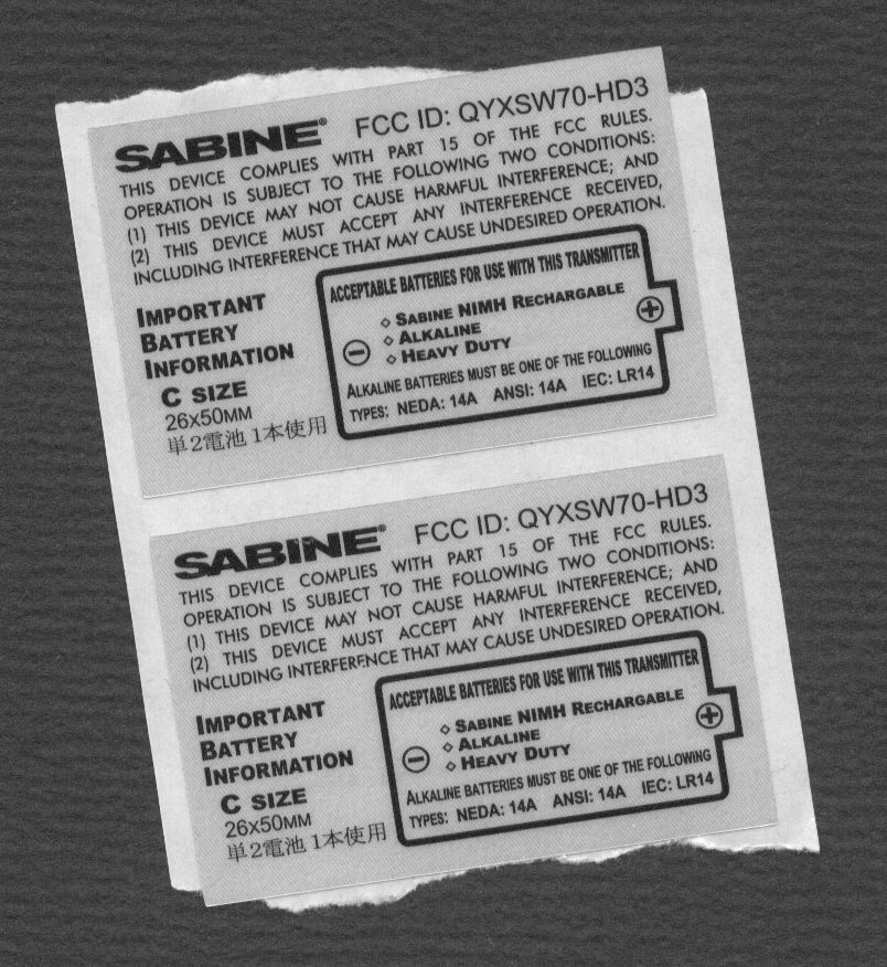
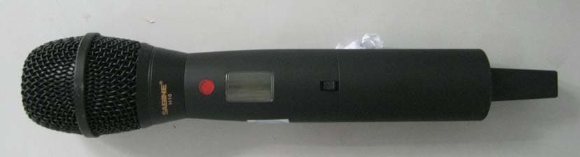
QYXSW70-HD3Handheld Microphone
Sabine, Inc.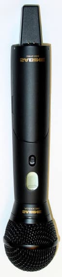
Click to zoom
Application Details
- Equipment Class
- DXX - Part 15 Low Power Communication Device Transmitter
- Date of Grant
- Apr 29, 2003
- Application Purpose
- Original Equipment
- Date of Application
- Apr 29, 2003
- Equipment Note
- Handheld Microphone
- Frequency Range
- 2400.80000000 - 2482.50000000
- Company
- Sabine, Inc.
- Country
- United States
Documents & Files
Document Text
Text extracted from the exhibit documents filed with the FCC. Open a document above to read the original.
Users Manual
58 Sabine 2.4 GHz Smart Spectrum Wireless Warning! This equipment must be earthed. Caution! Risk of electric shock. Do not open. Caution! Shock hazard. Do not remove covers. No user serviceable parts inside. Refer servicing to qualified service personnel. Warning! To reduce the risk of fire or electric shock, do not expose this product to rain or moisture. Attention! Cet appareil doit être relié à la terre. Attention! Risque de choc électrique; ne pas ouvrir. Attention! Risque de choc; ne pas oter les capots. Aucune pièce acces- sible à l’intérieur. S’addresser à un technicien qualifié. Attention! Pour réduire le risque d’incendie ou de choc électrique, ne pas laisser l’appareil sous la plouie ou à l’humidité. Achtung! Dieses Gerät muss schutzgeerdet sein. Achtung! Gefar eines elektrischen Stormschlags. Gehause nicht öffnen. Achtung! Gefar eines elektrischen Stormschlags. Gehäuse nicht öffnen. Keine con Benutzer zu bedienenden Teile im Geräteinneren. Überlassen Sie das Gerät zu Servicezwecken nur geschultem Fachpersonal. Um Brandgefar oder das Risiko eines elektrischen Schlags auszuschließen, das Gerät vor Nässe und Feuchtigkeit schützen. Advertencia! Este equipo debe estar conectado a tierra. Precaución! Reisgo de descarga eléctrica. No abrir. Precaución! Riesgo de descarga eléctrica. No desmontar las tapas. Piezas interiores no reparables por el usuario. Reparable sólo por per- sonal cualificado. Advertencia! Para reducir el riesgo de incendio o de descarga eléctrica no exponga este producto a la lluvia o humedad. FCC Statement This device complies with Part 15 of the FCC Rules. Operation is subject to the following two conditions: (1) This device may not cause harmful interference; and (2) This device must accept any interference received, including interference that may cause undesired operation. Warning: Changes or modifications to this unit not expressly approved by the party responsible for compliance could void the user’s authority to operate the equipment. NOTE: This equipment has been tested and found to comply with the limits for a Class B digital device, pursuant to Part 15 of the FCC Rules. These limits are designed to provide reasonable protection against harmful interference in a residential installation. This equipment gen- erates, uses, and can radiate radio frequency energy and, if not in- stalled and used in accordance with the instructions, may cause harmful interference to radio communications. However, there is no guarantee that interference will not occur in a particular installation. If this equip- ment does cause harmful interference to radio or television reception, which can be determined by turning the equipment off and on, the user is encouraged to try to correct the interference by one or more of the following measures: •Reorient or relocate the receiving antenna. •Increase the separation between the equipment and receiver. •Connect the equipment into an outlet on a circuit different from that to which the receiver is connected. •Consult the dealer or an experienced radio TV technician for help. Canadian Compliance Statement This digital apparatus does not exceed the Class B limits for radio noise emissions from digital apparatus set out in the Radio Interference Regulations of the Canadian Department of Communications. Le present appareil numerique n’emet pas de bruits radioelectriques depassant les limites applicables aux appareils numeriques de la class B prescrites dans le Reglement sur le brouillage radioelectrique edicte par le ministere des Communications du Canada. Japanese EMI Compliance Statement The True Mobility is designed to operate from standard AC power. Please be sure the power in your area is compatible with the power requirements marked on the rear of the unit. Using the wrong input voltage may cause permanent damage to the unit and will void the warranty. The True Mobility Wireless Microphone system is supplied with one of the following AC power cords: Japan100 VAC U.S./North America 120 VAC Continental Europe230 VAC United Kingdom240 VAC Australia240 VAC WARNING! Battery Caution DO NOT BURN OR PUNCTURE BATTERY. DOING SO COULD RELEASE TOXIC MATERIALS WHICH COULD CAUSE INJURY. DO NOT SHORT CIRCUIT MUST BE RECYLED OR DIS- POSED OF PROPERLY. 1. Read all safety and operating instructions before using this prod- uct. 2. All safety and operating instructions should be retained for future reference. 3. Obey all cautions in the operating instructions and on the unit. 4. All operating instructions should be followed. 5. Use only shielded audio and data cables. 6. This product should not be used in the presence of moisture or rain, or near any water, i.e., a bathtub, sink, swimming pool, wet basement, etc. 7. This product should be located so that its position does not inter- fere with proper ventilation. Do not use in direct sunlight. Do not place flat against a wall or in a built-in enclosure that will impede the flow of cooling air. 8. This product should not be placed near a source of heat such as a stove or radiator. 9. Connect only to a power supply of the type marked on the unit adjacent to the power entry module. 10. Never break off the ground pin on the power supply cord. 11. Power supply cords should always be handled carefully. Never walk or place equipment on power supply cords. Periodically check cords for cuts or signs of stress, especially at the plug and the point where the cord exits the unit. 12. The power supply cord should be unplugged when the unit is to be unused for long periods of time. 13. Care should be taken so that objects do not fall and liquids are not spilled into the unit through the ventilation holes or any other openings. 14. This unit should be checked by a qualified service technician if: A. The power supply cord or plug has been damaged. B. Anything has fallen or been spilled into the unit. C. The unit does not operate correctly. D. The unit has been dropped or the enclosure damaged. 15. The user should not atte…
Text truncated - open the document above for the full version.
Users Manual
Sabine 2.4 GHz Smart Spectrum ™ Wireless Systems Operating Guide (Beta 02.10.22) ® 2 Sabine 2.4 GHz Smart Spectrum Wireless (BETA) Declaration of Conformity Manufacturer's Name:Sabine, Inc. Manufacturer's Address:13301 NW US Highway 441 Alachua, FL 32615 USA Type of Equipment:Wireless Microphone Systems Model No.:SWM7000 Serial No.: Year of Manufacture:2002 I, the undersigned, hereby declare that the equipment specified above conforms to the above Directive and Standard. Place: Alachua, Florida, USASignature: Date: October 31, 2002Full Name:Doran Oster, Sabine President DECLARATION OF CONFORMITY Application of Council Directive: 73/23/EEC and 89/336/EEC Standards to which conformity is declared: EN 60065: 1993 EN 60742: 1995 EN 55103-1: 1997 EN 55022: 08:94 + a1:05:05 EN 55103-2: 1997 3 Sabine 2.4 GHz Smart Spectrum Wireless (BETA) B1-SWM7000-OpGuide.pmd - 021022 - hto Table of Contents DECLARATION OF CONFORMITY.......................................................................................................................................... 2 1. INTRODUCTION .................................................................................................................................................................. 4 1.1. Section Contents ......................................................................................................................................................... 4 1.2. Wireless Microphones ................................................................................................................................................ 5 2. PRODUCT VIEWS ............................................................................................................................................................... 8 2.1. Receivers ..................................................................................................................................................................... 8 2.2. Transmitters ................................................................................................................................................................ 9 2.3. Components................................................................................................................................................................ 9 3. QUICK SETUP ................................................................................................................................................................... 10 3.1. Receiver & Transmitter .............................................................................................................................................. 10 3.2. FBX Quick Setup ........................................................................................................................................................ 11 4. TRANSMITTER OPERATION............................................................................................................................................. 12 4.1. First step .................................................................................................................................................................... 12 4.2. Displays and Settings ............................................................................................................................................... 12 5. RECEIVER OPERATION .................................................................................................................................................... 18 5.1. LCD Display. .............................................................................................................................................................. 18 5.2. Parameter Control & LCD Display ............................................................................................................................ 20 5.3. RF Channel Select .................................................................................................................................................... 21 5.4. Output Level ............................................................................................................................................................... 21 5.5. Receiver Antenna Placement .................................................................................................................................... 22 6. MIC SUPERMODELING™................................................................................................................................................. 24 6.1. Introduction ................................................................................................................................................................ 24 6.2. Emulation Choices .................................................................................................................................................... 24 6.3. Mic Modeling Front Panel Control ............................................................................................................................. 25 6.4. Future Microphone Modeling Choices ...................................................................................................................... 25 7. FBX FEEDBACK EXTERMINATOR®.................................................................................................................................. 26 7.1. FBX Set Up ................................................................................................................................................................. 26 7.2. FBX Bypass Button .................................................................................................................................................... 27 8. COMPRESSOR/LIMITER OPERATION ............................................................................................................................. 28 8.1. Basics of Compression ...............…
Text truncated - open the document above for the full version.
Users Manual
38 Sabine 2.4 GHz Smart Spectrum Wireless (BETA) Multiple Systems Operation 13. REMOTE CONTROL OPERATION 13.1. Overview In many circumstances you will adjust and control your Sabine SWM7000 wireless microphone system using the front panel controls, as outlined in previous sections of this operating guide. In circum- stances where an enhanced level of control over a single receiver is desired, or to enable simultaneous computer-based control of multiple receivers, you will need to install (on either a laptop or desktop com- puter) the free Sabine SWM Remote Control Software Software included with your system. Only receivers may be remotely controlled; handheld and belt pack transmitters cannot be remotely controlled. For online instructions for any function in the software, you may also refer to the Help menu. 13.1.1. Single Receiver vs. Multiple Receiver Remote Control All SWM7000 series receivers have an RS-232 jack on the back for serial connection to your computer. Thus, any single receiver can be controlled remotely. Control over multiple receivers from a single com- puter is possible only for ND-series (SW51ND-R and SW52ND-R) re- ceivers. These units have additional RS-485 network connections (RJ- 45 jacks) for daisy-chain connection from one receiver to the next. Up to 35 receivers (70 transmission channels if all receivers are 2-channel) may be connected in this network, all under the control of a single computer. Single and dual channel receivers can be mixed in the same network. The first receiver in such a network can be connected to the computer via an RS-232 or RS-485 serial cable; the remaining units will then be connected via RS-485. It is not possible to upgrade/retrofit a standard receiver to make it an ND-series unit. 13.1.2 Features & Controls Added by SWM Remote Software All front panel controls and displays are duplicated in the software. In addition, a deeper level of software control over receiver operation is enabled. These new controls are complete and independent for each transmission/reception channel, meaning there are two sets of con- trols for dual channel receivers. These controls and displays include: •Parametric filter access and control. FBX filters can be changed to parametric filters, and their width, depth, and frequency can be adjusted. Changes can be made at any time, both before and after FBX filters have been set. Parametric and FBX filters can be mixed in any combination, totaling 12 for each receiver channel. •Adjustable FBX parameter control. Maximum depth of FBX fil- ters can be adjusted globally; filter width can be adjusted globally or individually. Two controls, Sensitivity and Persistence, can be tweaked to tailor the operation of automatic FBX filter placement to match the audio program. Proper settings will optimize the bal- ance between false filtering and delayed response to feedback (the factory default settings should operate excellently in the vast ma- jority of conditions and may never need to be changed). •Control over balance of FBX Fixed and Dynamic filters. Any FBX filter can be set to be either fixed or dynamic. Tech Tip Front Panel Control LOCK 1 —All front panel controls are locked. LOCK 2 —Programmable lock; you can select which con- trols are locked. 39 Sabine 2.4 GHz Smart Spectrum Wireless (BETA) B3-SWM7000-OpGuide.pmd - 021022 - hto Multiple Systems Operation •Adjustable high and low cut filters. High Cut Filter, user-control- lable between 3 KHz and 20 KHz; 12dB/octave roll-off •Additional compressor controls. Aside from adjustments for ratio, threshold, and attack (which duplicate front panel controls), the Remote Software provides control of compressor release time and knee. The effect of compression on the output signal as a function of input signal strength and parameter settings is displayed in Sabine’s unique dynamic ColorComp graph, in addition to the traditional opposing-meter indicators. •RF Scan and Report, which measures strength for each of the 70 transmission channels, and displays a hierarchical ordering of the clearest, strongest channels to use during system setup and op- eration. You can print a copy of the scan results. •Additional memory options. In addition to saving presets in re- ceiver memory, channel configuration settings can be saved to and recalled from disc or hard drive. All parameter settings made with the remote control, including adjustments that are not accessible from front panel controls (e.g., compressor knee and release), are saved with presets. All software settings stored for each of the 15 presets, including settings not accessible from the front panel, will be loaded whether presets are recalled by remote control or from the front panel. Note that all settings made in Off-line/Edit mode can be saved and applied in online operation.. •Ability to print a report of all parameter settings, creating hard copy documentation. •A receiver channel output mute button. •The ability to custom name each RF channel and receiver. This name will be displayed in both software operation, and on the re- ceiver front panel. •Display of important transmitter status information. In addi- tion to duplicating the battery charge status, battery warning mes- sage, and transmitter on/off/mute status from the front panel dis- play, the Remote Software displays the type of battery in use, the number of hours the battery has been in use, the frequency mid- point (in GHz) of the transmission channel chosen, the transmitter pad and low cut filter settings, and a warning indication in the case of low RF signal strength. For handheld transmitters, the software display also shows the type of mic capsule in use. •Improved and expanded operational displays. In addition to organizing all front panel displays on a single computer screen, the Remote Software also displays the exact frequency, width, and depth of FBX filters. The frequency response curve resulting from combined filter settings (including FBX, parametric…
Text truncated - open the document above for the full version.
Users Manual
45 Sabine 2.4 GHz Smart Spectrum Wireless (BETA) B3-SWM7000-OpGuide.pmd - 021022 - hto Fig. 13m Copy Parameters window Fig. 13n Reset Parameters window 13.4.2.6. Options13.4.2.6. Options 13.4.2.6. Options13.4.2.6. Options 13.4.2.6. Options Copy Parameters. This window allows you to copy your settings for all functions to any number of other channels. Select the channel you want to copy from by first selecting the receiver, then the channel. From the Options Menu, choose Copy Parameters. You will see your selected chan- nel displayed in a red field labeled “Copy Parameters From.” Select the channels you want to copy to from the Available Channels list, then check the boxes of the parameters you wish to copy. Once you are sure of your selections, hit Copy Now and your settings will be pasted to the selected channels. Note that RF channel selections cannot be cop- ied. Reset Parameters. This window allows you to selectively reset any of the functions in your receiver. Choose Reset Parameters from the Options Menu, then check the boxes of the func- tions you would like to reset to their default settings. In order to reset FBX filters, use the dedicated button on the Command View. If you wish to load the factory default for the entire receiver, choose Preset 00 from the Program drop-down on the Command View and select the Load button. 46 Sabine 2.4 GHz Smart Spectrum Wireless (BETA) 14.1. Introduction to FBX® WHY FBX? Feedback is certainly the most perva- sive challenge to the audio industry. The potential appearance of sudden, loud, out-of-control feedback is every sound engineer’s and musician’s nightmare. Unlike more subtle audio quality problems or short- comings, feedback is embarrassingly obvious — it disturbs the performer, the audience, and the techni- cian, and can damage equipment and just generally ruin your day. Feedback is a potential problem in any amplified sound system that places a microphone or pickup in prox- imity to a loudspeaker. Poor acoustical conditions or misguided use by unsophisticated sound system op- erators only aggravate the situation. To make mat- ters still worse, a non-Sabine variety of wireless mi- crophone adds yet another level of feedback danger to the picture. Since feedback erupts whenever the distance, location, and gain relationships between a speaker and a microphone reach a critical combina- tion, a mic that can move anywhere results in an ever changing potential for feedback. A step in the wrong direction may change a clear sound to a pierc- ing shriek in less than a second. This enhanced potential for feedback with a wireless system gets worse if lavalier microphones are used. Such microphones are usually placed farther from the mouth than handheld or head set microphones, thus requiring more gain. Also, the polar pattern of a lavalier microphone is frequently omni-directional. Thus, the likelihood of feedback increases, due to the microphone’s increased off-axis sensitivity to the sound emanating from the loudspeakers. The Sabine True Mobility™ SWM7000 wireless sys- tems solve feedback problems by precise attenua- tion of very narrow bands of feedback-prone frequen- cies. The process is automatic, simple to use, adapt- able to changing acoustical conditions and relation- ships, powerful in its application, and has minimal consequences to the audio fidelity of the signal. We call this automatic filter a Feedback Exterminator ® filter, or FBX filter for short. -10 dB cut at 500, 630, 1K, 1.25K, 1.6K & 2K Hz If the graphic EQ really had 1/3 octave filter widths, the frequency response curve would vary 6 dB between sliders. This would ruin the sound. Graphic EQs usually use one-octave-wide overlapping filters that provide much smoother frequency response curves. No- tice that the overlapping filters add to- gether to cut -16 dB when the sliders are only pulled down -10 dB. FBX Feedback Exterminator® Theory & Practice 14. FEEDBACK CONTROL THEORY & PRACTICE Fig. 14a What a Graphi-Q does to your Program 47 Sabine 2.4 GHz Smart Spectrum Wireless (BETA) B4-SWM7000-OpGuide.pmd - 021022 - hto 14.2. The Advantages of FBX Filters Before the invention of FBX, the most common device for controlling feedback was the 31-band graphic EQ. However, an FBX filter offers three distinct advantages over graphic filters. 1. First and most obvious is the automatic nature of FBX filters. When feedback occurs, FBX responds more quickly than even the most experienced engineer. Automatic FBX placement works even in the presence of audio program material, intelligently distinguishing feed- back from music or speech. 2. A second advantage is that FBX micro-filters are precisely placed anywhere feedback occurs (with 1 Hz resolution), while graphic EQ filters are limited to 31 fixed center points. An FBX filter represents a direct hit on feedback! In contrast, a graphic EQ filter can only approximate the exact frequency of the feedback, and the filter (or filters) with the clos- est center frequency must be pulled down. Such filters are deepest at their centers, and such impre- cise attenuation takes a big (and unnecessary) chunk out of your sound (see figure 14b). 3. Increased clarity and gain-before-feedback are further accomplished by the third and most impor- tant advantage of FBX: Sabine’s micro-filters are ten times narrower than 31-band EQ filters. Using FBX micro-filters will return up to 90 percent of the power removed by EQ filters. Here’s a good place to make a very important dis- tinction. Graphic EQ filters are typically called “1/ 3-octave,” but it’s important to understand that this term refers to the spacing of the filter centers (1/3- octave apart), and not the width of the filter (usually a full octave). Graphic filters thus overlap one an- other, and affect frequencies well above and below the center point frequency, including frequencies of adjacent bands. This makes graphic equalizers very practical tools for shaping sound “with broad strokes,” such as diali…
Text truncated - open the document above for the full version.
Test Report
APPLICANT: SABINE, INC. FCC ID: QYXSW70-HD3 REPORT #: S\SABINE\134UT3\134UT3TestReport.doc PAGE: 1 of 11 TABLE OF CONTENTS APPLICANT: SABINE, INC. FCC ID: QYXSW70-HD3 TEST REPORT CONTAINING: PAGE 1-3.........TEST EQUIPMENT LIST PAGE 4...........TEST PROCEDURE PAGE 5...........RADIATION INTERFERENCE TEST DATA PAGE 6...........OCCUPIED BANDWIDTH PAGE 7...........OCCUPIED BANDWIDTH PLOT PAGE 8...........POWER LINE CONDUCTED PAGE 9-10........POWER LINE CONDUCTED PLOTS EXHIBIT ATTACHMENTS: EXHIBIT 1.........FCC ID LABEL SAMPLE EXHIBIT 2.........SKETCH OF FCC ID LABEL LOCATION EXHIBIT 3.........BLOCK DIAGRAM EXHIBIT 4A-M......SCHEMATICS EXHIBIT 5.........INSTRUCTION MANUAL EXHIBIT 6A-B......EXTERNAL PHOTOGRAPHS EXHIBIT 7A-C......INTERNAL PHOTOGRAPHS EXHIBIT 8.........CIRCUIT DESCRIPTION EXHIBIT 9A-B......TEST SET UP PHOTOS APPLICANT: SABINE, INC. FCC ID: QYXSW70-HD3 REPORT #: S\SABINE\134UT3\134UT3TestReport.doc PAGE: 1 of 11 EMC Equipment List DEVICE MFGR MODEL SERNO CAL/CHAR DATE DUE DATE or STATUS X 3-Meter OATS TEI N/A N/A Listed 12/22/99 12/22/02 3/10-Meter OATS TEI N/A N/A Listed 3/26/01 3/26/04 Receiver, Beige Tower Spectrum Analyzer (Tan) HP 8566B Opt 462 3138A07786 3144A20661 CAL 8/31/01 8/31/03 RF Preselector (Tan) HP 85685A 3221A01400 CAL 8/31/01 8/31/03 Quasi-Peak Adapter (Tan) HP 85650A 3303A01690 CAL 8/31/01 8/31/03 X Receiver, Blue Tower X Spectrum Analyzer (Blue) HP 8568B 2928A04729 2848A18049 CHAR 10/22/01 10/22/03 X RF Preselector (Blue) HP 85685A 2926A00983 CHAR 10/22/01 10/22/03 X Quasi-Peak Adapter (Blue) HP 85650A 2811A01279 CHAR 10/22/01 10/22/03 X Biconnical Antenna Electro-Metrics BIA-25 1171 CAL 4/26/01 4/26/03 Biconnical Antenna Eaton 94455-1 1096 CAL 10/1/01 10/1/03 Biconnical Antenna Eaton 94455-1 1057 CHAR 3/15/00 3/15/02 BiconiLog Antenna EMCO 3143 9409-1043 X Log-Periodic Antenna Electro-Metrics LPA-25 1122 CAL 10/2/01 10/2/03 Log-Periodic Antenna Electro-Metrics EM-6950 632 CHAR 10/15/01 10/15/03 Log-Periodic Antenna Electro-Metrics LPA-30 409 CHAR 10/16/01 10/16/03 Dipole Antenna Kit Electro-Metrics TDA-30/1-4 152 CAL 3/21/01 3/21/04 Dipole Antenna Kit Electro-Metrics TDA-30/1-4 153 CHAR 11/24/00 11/24/03 Double-Ridged Horn Antenna Electro-Metrics RGA-180 2319 CAL 12/19/01 12/19/03 Horn Antenna Electro-Metrics EM-6961 6246 CAL 3/21/01 3/21/03 Horn Antenna ATM 19-443-6R None No Cal Required Passive Loop Antenna EMC Test Systems EMCO 6512 9706-1211 CHAR 7/10/01 7/10/03 APPLICANT: SABINE, INC. FCC ID: QYXSW70-HD3 REPORT #: S\SABINE\134UT3\134UT3TestReport.doc PAGE: 2 of 11 DEVICE MFGR MODEL SERNO CAL/CHAR DATE DUE DATE or STATUS Line Impedance Stabilization . . . Electro-Metrics ANS-25/2 2604 CAL 10/9/01 10/9/03 Line Impedance Stabilization . . . Electro-Metrics EM-7820 2682 CAL 3/16/01 3/16/03 Termaline Wattmeter Bird Electronic Corporation 611 16405 CAL 5/25/99 5/25/01 Termaline Wattmeter Bird Electronic Corporation 6104 1926 CAL 12/12/01 12/12/03 Oscilloscope Tektronix 2230 300572 CHAR 2/1/01 2/1/03 Temperature Chamber Tenney Engineering TTRC 11717-7 CHAR 1/22/02 1/22/04 AC Voltmeter HP 400FL 2213A14499 CAL 10/9/01 10/9/03 AC Voltmeter HP 400FL 2213A14261 CHAR 10/15/01 10/15/03 AC Voltmeter HP 400FL 2213A14728 CHAR 10/15/01 10/15/03 X Digital Multimeter Fluke 77 35053830 CHAR 1/8/02 1/8/04 Digital Multimeter Fluke 77 43850817 CHAR 1/8/02 1/8/04 Digital Multimeter HP E2377A 2927J05849 CHAR 1/8/02 1/8/04 Multimeter Fluke FLUKE-77-3 79510405 CAL 9/26/01 9/26/03 Peak Power Meter HP 8900C 2131A00545 CHAR 1/26/01 1/26/03 Digital Thermometer Fluke 2166A 42032 CAL 1/16/02 1/16/04 Thermometer Traulsen SK-128 CHAR 1/22/02 1/22/04 X Temp/Humidity gauge EXTech 44577F E000901 CHAR 1/22/02 1/22/04 Frequency Counter HP 5352B 2632A00165 CAL 11/28/01 11/28/03 Power Sensor Agilent Technologies 84811A 2551A02705 CAL 1/26/01 1/26/03 Service Monitor IFR FM/AM 500A 5182 CAL 11/22/00 11/22/02 Comm. Serv. Monitor IFR FM/AM 1200S 6593 CAL 5/12/02 5/12/04 Signal Generator HP 8640B 2308A21464 CAL 11/15/01 11/15/03 Modulation Analyzer HP 8901A 3435A06868 CAL 9/5/01 9/5/03 Near Field Probe HP HP11940A 2650A02748 CHAR 2/1/01 2/1/03 APPLICANT: SABINE, INC. FCC ID: QYXSW70-HD3 REPORT #: S\SABINE\134UT3\134UT3TestReport.doc PAGE: 3 of 11 DEVICE MFGR MODEL SERNO CAL/CHAR DATE DUE DATE or STATUS BandReject Filter Lorch Microwave 5BR4-2400/ 60-N Z1 CHAR 3/2/01 3/2/03 BandReject Filter Lorch Microwave 6BR6-2442/ 300-N Z1 CHAR 3/2/01 3/2/03 BandReject Filter Lorch Microwave 5BR4-10525/ 900-S Z1 CHAR 3/2/01 3/2/03 High Pas Filter Microlab HA-10N CHAR 10/4/01 10/4/03 Audio Oscillator HP 653A 832-00260 CHAR 3/1/01 3/1/03 Frequency Counter HP 5382A 1620A03535 CHAR 3/2/01 3/2/03 Frequency Counter HP 5385A 3242A07460 CHAR 12/11/01 12/11/03 Preamplifier HP 8449B-H02 3008A00372 CHAR 3/4/01 3/4/03 Amplifier HP 11975A 2738A01969 CHAR 3/1/01 3/1/03 Egg Timer Unk CHAR 8/31/01 8/31/03 Measuring Tape, 20M Kraftixx 0631-20 CHAR 2/1/02 2/1/04 Measuring Tape, 7.5M Kraftixx 7.5M PROFI 2/1/02 2/1/04 Coaxial Cable #51 Insulated Wire Inc. NPS 2251-2880 Timco #51 CHAR 1/23/02 1/23/04 Coaxial Cable #64 Semflex Inc. 60637 Timco #64 CHAR 1/24/02 1/24/04 Coaxial Cable #65 General Cable Co. E9917 RG233/U Timco #65 CHAR 1/23/02 1/23/04 Coaxial Cable #106 Unknown Unknown Timco #106 CHAR 1/23/02 1/23/04 APPLICANT: SABINE, INC. FCC ID: QYXSW70-HD3 REPORT #: S\SABINE\134UT3\134UT3TestReport.doc PAGE: 4 of 11 TEST PROCEDURE GENERAL: This report shall NOT be reproduced except in full without the written approval of TIMCO ENGINEERING, INC. The UUT was transmitting a test signal during the testing. RADIATION INTERFERENCE: The test procedure used was ANSI STANDARD C63.4-1992 using a HEWLETT PACKARD spectrum analyzer with a preselector. The analyzer was calibrated in dB above a microvolt at the output of the antenna. The resolution bandwidth was 100KHz and the video bandwidth was 300KHz up to 1.0GHz and 1.0MHz with a video BW of 3.0MHz above 1.0GHz. The ambient temperature of the UUT was 55ºF with a humidity of 43%. FORMULA OF CONVERS…
Text truncated - open the document above for the full version.
Contact Information
Applicant
Byra Ferkovich(Senior Engineer)
Test Firm
Timco Engineering, Inc.S Sanders
Technical Specifications
| # | Rule Parts | Frequency Range | Power Output |
|---|---|---|---|
| 1 | 15C | 2.40 GHz - 2.48 GHz | - |
Other Applications from Sabine, Inc.
QYXSW40-H
Aug 25, 2011Handheld Transmitter
Equipment Class
DXX - Part 15 Low Power Communication Device Transmitter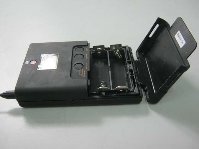
QYXSW45-T
Aug 25, 2011Bodypack Transmitter
Equipment Class
DXX - Part 15 Low Power Communication Device Transmitter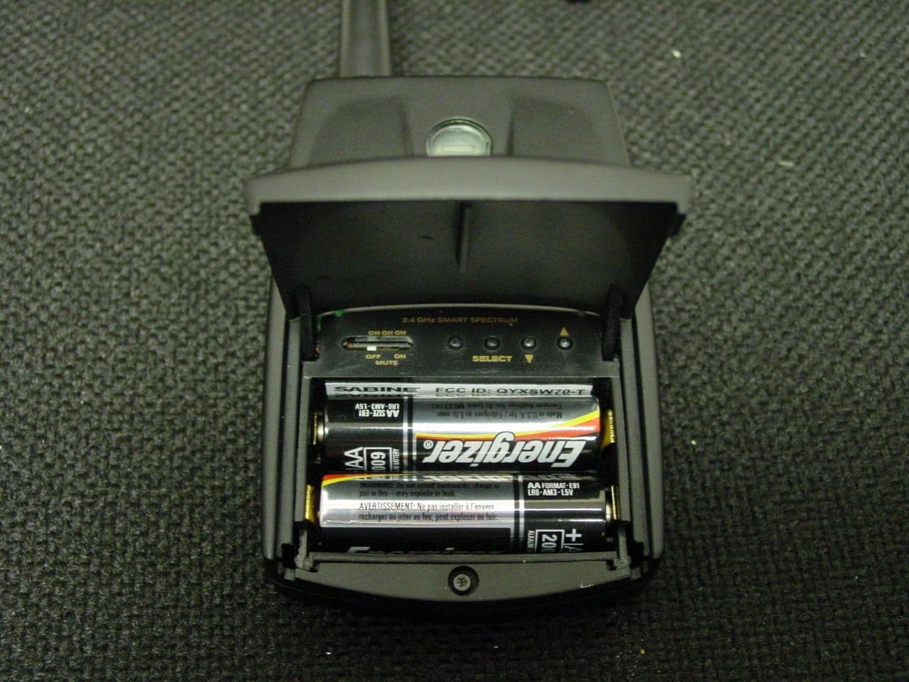
QYXSW70-T
Dec 18, 2003BELTPACK TRANSMITTER
Equipment Class
DXX - Part 15 Low Power Communication Device Transmitter