QYXSW70-TBELTPACK TRANSMITTER
Sabine, Inc.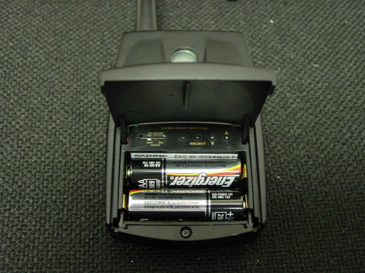
Click to zoom
Application Details
- Equipment Class
- DXX - Part 15 Low Power Communication Device Transmitter
- Date of Grant
- Dec 18, 2003
- Application Purpose
- Original Equipment
- Date of Application
- Dec 18, 2003
- Equipment Note
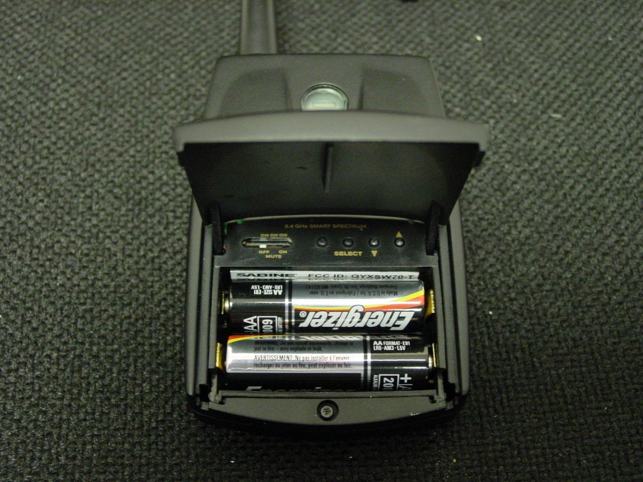
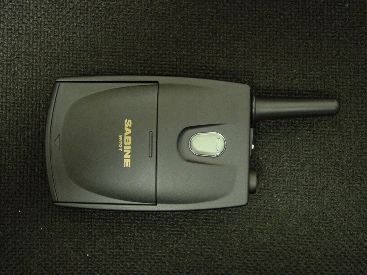
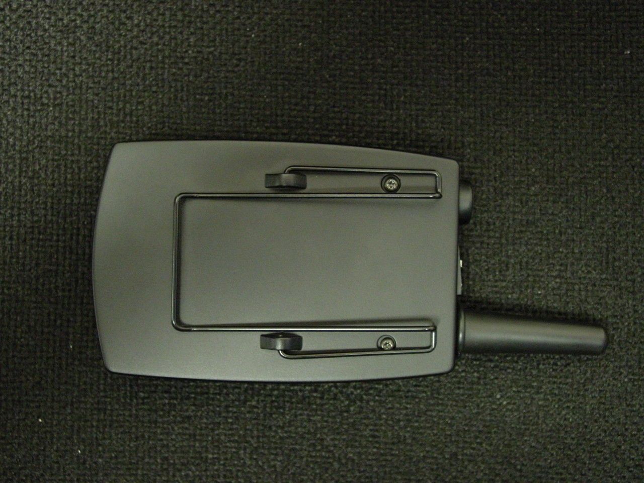
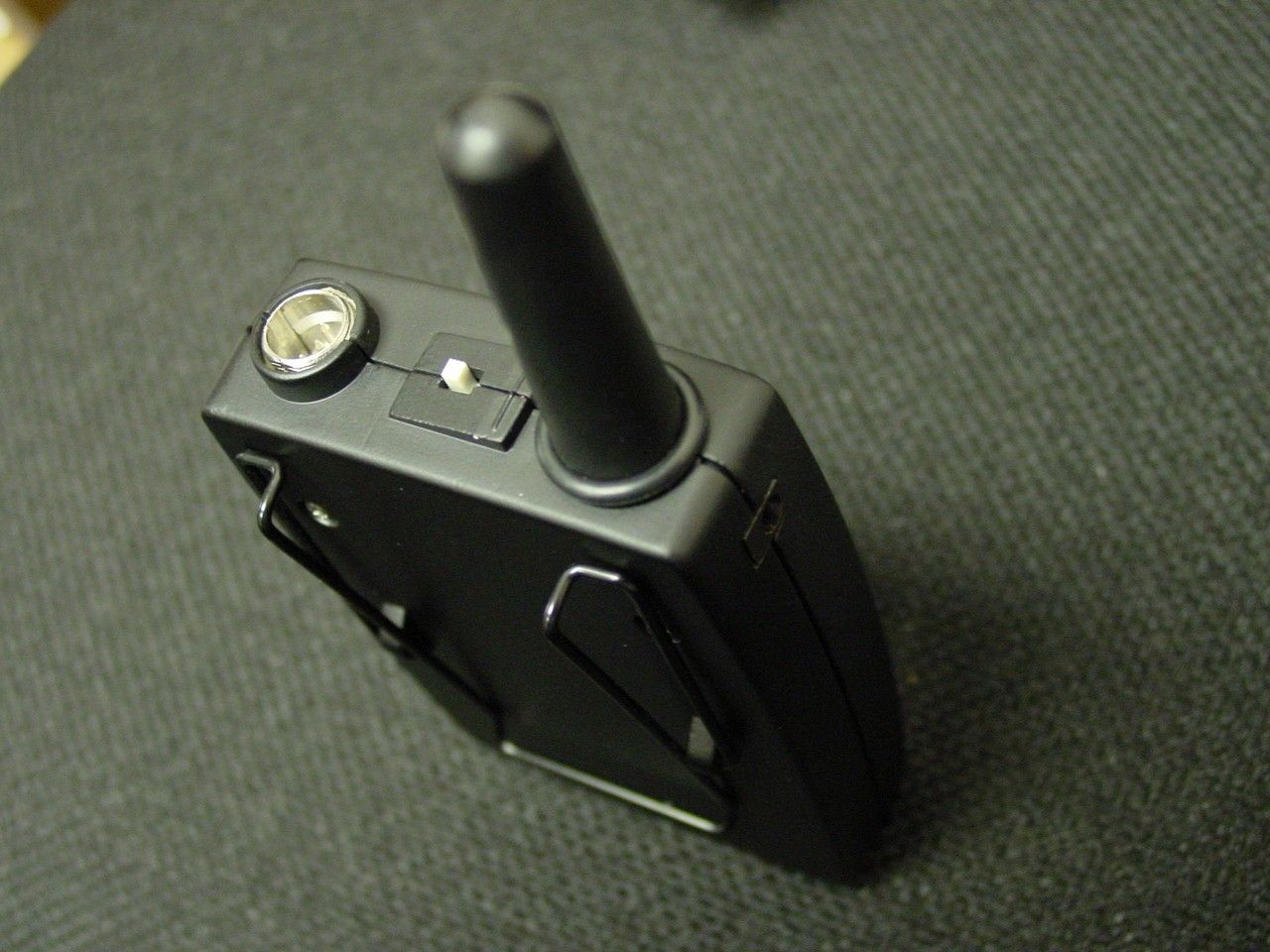
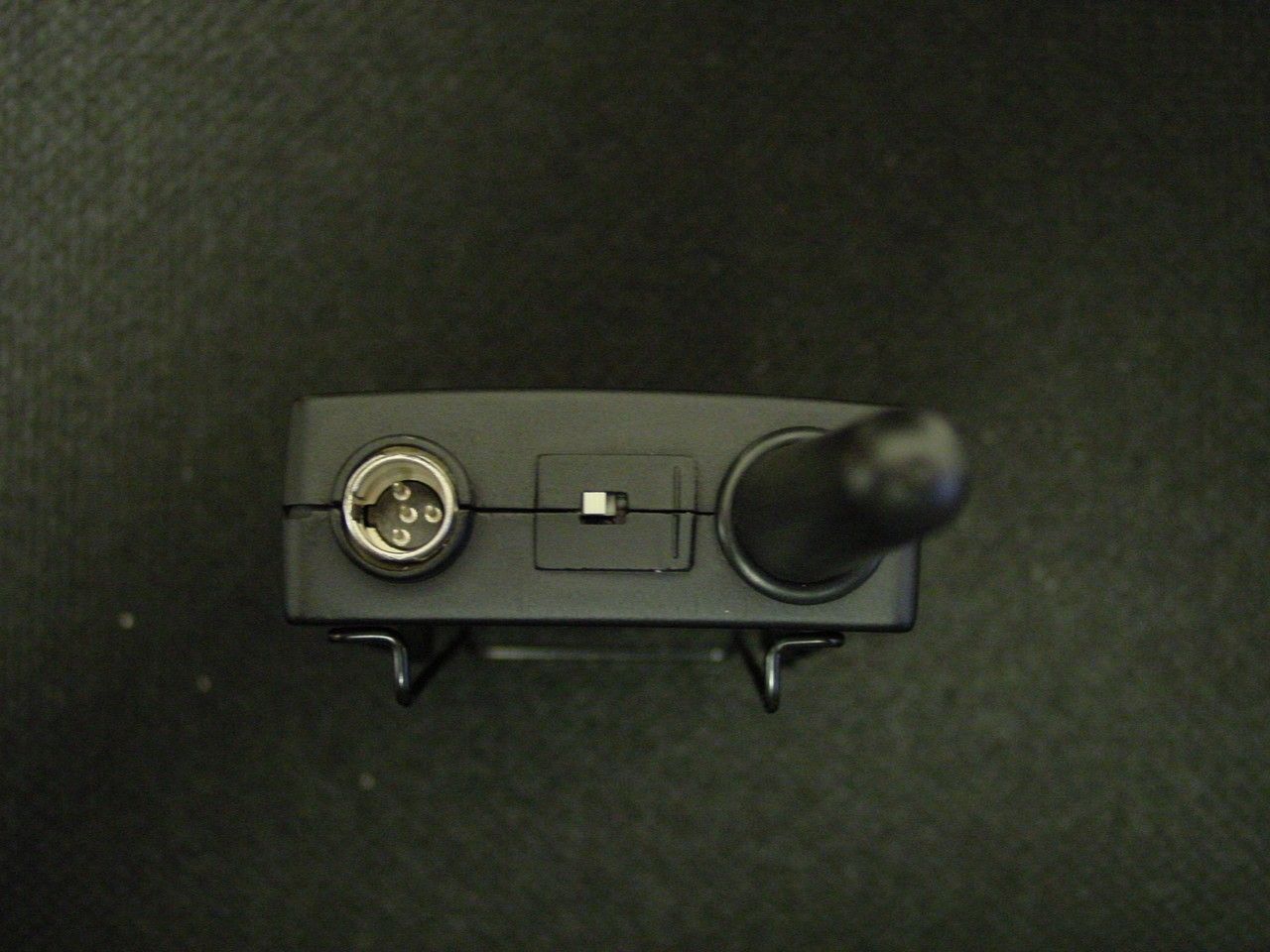
- BELTPACK TRANSMITTER
- Frequency Range
- 2400.80000000 - 2482.50000000
- Company
- Sabine, Inc.
- Country
- United States
Documents & Files
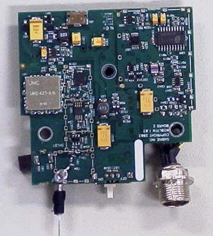
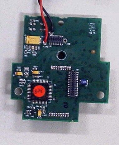
Document Text
Text extracted from the exhibit documents filed with the FCC. Open a document above to read the original.
Users Manual
1 Sabine 2.4 GHz Smart Spectrum ® Wireless E-SWM7000-OpGuide-031211.pmd - hto Declaration of Conformity EC - DECLARATION OF CONFORMITY CE MARKING We, the Manufacturer SABINE, INC. 13301 NW US HIGHWAY 441 ALACHUA, FLORIDA USA declare that the product RECEIVER SABINE MODEL SWM7000 Is in conformity with Council Directive: 73/23/EEC and 89/336/EEC (EMC Directives) Standards to which conformity is declared: EN 60065: 2001 EN 55022: 1998 Class B EN 50082-1: 1998 Manufacturer Signature:__________________________ Date: __________Name:__________________________ Doran Oster, President28 April, 2003 2 Sabine 2.4 GHz Smart Spectrum ® Wireless Table of Contents This operating guide written for USB enabled receivers using Sabine SWM7000 Remote Control Software version 2.0 and above. 1. INTRODUCTION3 1.1. Section Contents3 2. PRODUCT VIEWS4 2.1. Receivers4 2.1.1. Front panel views4 2.1.2. Back panel Views4 2.2. Transmitters5 2.2.1. Handheld5 2.2.2. Beltpack5 2.3. Components5 3. QUICK SETUPS6 3.1. Receiver & Transmitter Quick Setup6 3.2. FBX Quick Setup6 3.3. Tips for Good RF Performance10 3.4. Common Sources of RF Interference10 4. TRANSMITTER OPERATION12 4.1. First step12 4.2. Displays and Settings12 4.2.1. LCD Display12 4.2.2. Accessing Transmitter Controls13 4.2.3. Adjusting Transmitter Settings14 4.2.4. Transmitter Battery Management15 5. RECEIVER OPERATION18 5.1. LCD Display.18 5.2. Parameter Control & LCD Display20 5.2.1. One set of Controls for 1 or 2 Channels20 5.2.2. Channel Select / Contrast Button.20 5.2.3. Special LCD Display Messages.21 5.3. RF Channel Select21 5.4. Output Level21 5.5. Receiver Antenna Placement22 5.5.1. Multi-path Interference22 5.5.2. Receiver & Antenna Placement Tips22 6. MIC SUPERMODELING™24 6.1. Introduction24 6.2. Emulation Choices24 6.3. Mic Modeling Front Panel Control24 6.4. Future Microphone Modeling Choices25 6.4.1. Mic Model Upgrade Instructions25 7. FBX FEEDBACK EXTERMINATOR®26 7.1. FBX Introduction26 7.1.1. FBX Fixed Filters26 7.1.2. FBX Dynamic Filters26 7.1.3. Balancing Fixed & Dynamic Filters26 7.1.4. FBX Filter Width26 7.2. FBX Set Up26 7.2. FBX Bypass Button27 8. COMPRESSOR/LIMITER OPERATION28 8.1. Basics of Compression28 8.2. Using the Compressor28 8.3. Suggested Compression Settings29 8.3.1. Vocal Settings29 8.3.2. Guitar Settings29 8.3.3. Bass Guitar Settings29 8.5. Release & Knee Settings30 9. DE-ESSER31 9.1. De-mystifying De-essers31 9.2. The Sabine De-esser31 9.3. Using the De-esser31 10. PROGRAM SAVE & RECALL32 10.1. Saving a Preset32 10.2. Loading a Preset32 10.3. Naming a Preset32 10.4. Power Off Memory32 11. MULTIPLE SYSTEMS OPERATION33 11.1. Overview33 11.1.1. Multiple System Interference33 11.1.2. Setup Complexity33 11.2. Antenna Distribution Amplifier34 11.3. Antenna Distribution Amplifier Connection35 12. EXTENSION ANTENNAS36 12.1. Overview36 12.2. Antenna Cabling & Cable Loss36 13. REMOTE CONTROL OPERATION38 13.1. Overview38 13.1.1. Single vs. Multiple Receiver Control38 13.1.2 Features & Controls Added Software38 13.1.3. Software Multiple Unit Control40 13.2. Software Installation40 13.2.1. Requirements & Recommendations40 13.2.2. Connections40 13.2.3. Installing the Software41 13.3. Launching the software41 13.3.1. Off-Line Edit/Demo41 13.3.2. Connecting Receivers.41 13.4. Remote Control Operation42 13.4.1. Two Views, Two Sets of Controls42 13.4.2. Menus, Icons & Hot Keys42 14. TIPS & TROUBLESHOOTING46 14.1. Tips for Maximum Performance46 14.2. Troubleshooting46 14.3. Common Sources of RF Interference47 14.3.1 RF Sources47 15. FBX THEORY & PRACTICE49 15.1. Introduction to FBX®49 15.2. The Advantages of FBX Filters49 15.3. Parametric Filters and FBX50 15.3.1. The FBX & True Mobility® Advantage51 14.3.2. FBX Fixed & Dynamic Filters51 14.3.3. FBX Filter Width52 14.3.4. Who Benefits from FBX?52 15. APPENDICES53 Appendix A: Beltpack Connector Wiring Diagrams53 Appendix B: Antenna System Diagrams53 Appendix C: Specifications54 Appendix D: Dip Switch Settings55 Appendix E: Frequency Chart55 Appendix F: Battery Endurance Tests (Typical)56 Appendix G: Changing Audix Mic Capsules (SW70-H) 56 16. CAUTIONS & WARRANTY57 INDEX59 3 Sabine 2.4 GHz Smart Spectrum ® Wireless E-SWM7000-OpGuide-031211.pmd - hto 1. INTRODUCTION Congratulations on purchasing a Sabine 2.4 GHz Smart Spectrum True Mobility™ Wireless System. True Mobility™ Wireless Systems give you all the built-in processing you need on every microphone, and offer unique and powerful features unavailable with any other wireless microphone 1.1. Section Contents Section 2Product Views — illustrates system components (front & back panel views, transmitters, accessory lists and part numbers). Section 3Quick Setup — gives the Quick Setup procedures for Receiver & Transmitter Operation and using the FBX Feedback Exterminator ® . Note that there is also a quick-start label on top of your True Mobility receiver for the Sabine FBX Feedback Exterminator ® , Compressor/Limiter and De-Esser functions. Section 4Transmitter Operation — details transmitter setup and operation. Section 5Receiver Operation — details receiver installation and setup. Section 6Mic SuperModeling™ — explains the use of the Sabine Mic SuperModeling™ and lists the microphones modeled. Section 7FBX Feedback Exterminator ® — explains how to set up your FBX filters. Section 8Compressor/Limiter — explains the use of the Compressor. Section 9De-Esser — details operation of the adaptive De-Esser. Section 10Program Save & Recall — explains how to save and recall individual program settings. Section 11Multiple Systems — how multiple systems interface, computer control of multiple systems, suggestions for maximizing the number of collocated systems. Section 12Extension Antennas — how to get maximum performance using a Sabine Extension Antennas (Antenna Distribution Amplifier also available for multi-receiver installations). Section 13Sabine Remote Control Software — how to control up to 70 channels from one PC. Section 14Tips & Troubleshooting …
Text truncated - open the document above for the full version.
Users Manual
30 Sabine 2.4 GHz Smart Spectrum ® Wireless 8.4. Possible Compression Trouble Areas Like any signal processing, compression can be misused, and improper application may cause undesirable side effects in the audio signal. Some of these problems include: 1.Noise. If the threshold for compression is set too low, and the output gain is raised substantially to make up for the gain loss of compression, the resulting output signal can be noisy. This is because the overall signal must be raised significantly to produce the same audible level, and the noise floor of your equipment will be amplified unnecessarily. This prob- lem will be exaggerated if the input signal level to the compressor is very low (which will already degrade the signal-to-noise ratio). 2.Breathing. In situations where the compression ratio is high, the thresh- old is low, and the release time of the compressor is short, the noise floor will modulate up and down as the audio signal rises above and falls below the threshold. 3. Over-compression. Applying too much compression to a mix can some- times result in such evened-out dynamics that the “life” of the music or speech has been removed or curtailed. Dynamic variation may be a major component of a performer’s message and command of the audience; don’t remove dynamics, just control them. This may be particularly true for percussive musical instruments such as drums. 8.5. Release & Knee Settings Two other important compressor variables are release time and knee. Re- lease time adjusts the speed with which compression stops and output gain returns to unity with input gain, once the input signal falls below the compres- sion threshold. Knee refers to the degree with which the full ratio of compres- sion is imposed once the input level threshold is approached and exceeded. A “hard knee” changes from no compression to maximum compression ex- actly and immediately at the threshold crossing; a “soft knee” gradually im- poses the full compression ratio as the input gain approaches and exceeds the threshold. In Sabine products, the “softness” of a knee can vary from 1-40, with the higher level representing the “softest” character. In such a setting, slight compression will begin well below the compression threshold, increase as the input gain crosses the threshold, and reach full compression well above the nominal threshold. Values for release time and knee are set at the factory: default release time is 250 mSec, and the default knee setting is a “soft” setting of 20. These defaults can be temporarily changed or reprogrammed using the Sabine True Mobility TM Remote Software (see Section 13 for details). Compressor Limiter 31 Sabine 2.4 GHz Smart Spectrum ® Wireless E-SWM7000-OpGuide-031211.pmd - hto 9. DE-ESSER 9.1. De-mystifying De-essers Certain consonant sounds produced by the human voice contain more energy than others, and have the potential to overload a microphone capsule. This can produce a disproportionately harsh result when amplified through a sound system, and/or recorded to analog or digital storage media. The most com- mon and obvious of these sounds (in English and many languages) is the “ssss” sound, associated with pronunciation of both “s” and soft “c” conso- nants, also the consonants “t,” “f,” “x” and sometimes “d.” The technical term for this particular vocal sound is “sibilance,” and the devices that control such sounds are typically called “de-essers” (or sometimes sibilance controllers). The frequency range of sibilance will vary depending on the singer/speaker, the consonant involved, the orientation to the microphone, the microphone itself, and the normal variations in human vocalization. Cardioid- pattern con- denser microphones are especially susceptible to sibilance problems, but the problem can also occur with other types and patterns of microphones. The range of frequencies affected by sibilance starts above 2 KHz, and generally tapers off above 10 KHz; in other words, sibilance is primarily a problem asso- ciated with higher frequencies (though not the upper octave of human hear- ing). 9.2. The Sabine De-esser The Sabine De-esser is essentially a type of frequency-band compressor, active in the 2-10 KHz range, and inactive below 2KHz and above 10 KHz. Sabine’s algorithm works by dynamically comparing band-specific and asso- ciated harmonic energy levels to the total signal energy. When spikes are detected that correspond to sibilance, a shelving filter is imposed on the ap- propriate frequency bands, and remains in place only for the duration of the sibilance. High frequency energy levels that remain below the comparison threshold do not trigger de-essing, and lows and highs outside the sibilance range are also passed unprocessed and unaffected. This means the Sabine De-esser is effective but transparent. 9.3. Using the De-esser Using the Sabine De-esser is simplicity itself. Turning the knob labeled “DE- ESS CUT” counterclockwise will increase the amount of sibilance reduction, by increasing the maximum depth of the shelving filter. The maximum allow- able cut is 24 dB. Fig. 9a: De-esser De-esser 32 Sabine 2.4 GHz Smart Spectrum ® Wireless Fig. 10e: Program PRESET LOADED 10. PROGRAM SAVE & RECALL Most wireless microphone systems provide control of one or two settings (RF channel and maybe gain). With so little to remember, the ability to save and recall system settings has not been necessary. With the Sabine SWM7000 series, however, you get a very sophisticated processor with a variety of adjust- able parameters. The ability to save and recall your carefully programmed setups can be a tremendous time-saver. Your SWM7000 allows you to store and recall up to 10 different presets. 10.1. Saving a Preset To save a program, press the SELECT button. The last preset used (num- bered 01 - 10) will be shown in the LCD Display (see Fig. 10b). If you want to replace an existing program, press SELECT until you reach that program’s number. Then press the SAVE butto…
Text truncated - open the document above for the full version.
Test Report
TIMCO ENGINEERING INC. 849 NW State Road 45 Newberry, Florida 32669 http://www.timcoengr.com 888.472.2424 F 352.472.2030 email: [email protected] APPLICANT: SABINE, INC. Test Report Product Name: WIRELESS MICROPHONE FCC ID: QYXSW70-T Applicant: SABINE, INC. 13301 HIGHWAY 441 ALACHUA, FL 32615-8544 Date Receipt: NOVEMBER 5, 2003 Date Tested: NOVEMBER 11, 2003 FCC ID: QYXSW70-T REPORT #: S\SABINE\1236YUT3\1236YUT3TestReport.doc TITLE PAGE TIMCO ENGINEERING INC. 849 NW State Road 45 Newberry, Florida 32669 http://www.timcoengr.com 888.472.2424 F 352.472.2030 email: [email protected] APPLICANT: SABINE, INC. TABLE OF CONTENTS APPLICANT: SABINE, INC. FCC ID: QYXSW70-T TEST REPORT CONTAINING: PAGE 1...........TEST EQUIPMENT LIST PAGE 2...........TEST PROCEDURE PAGE 3...........RADIATION INTERFERENCE TEST DATA PAGE 4...........OCCUPIED BANDWIDTH PAGE 5...........OCCUPIED BANDWIDTH PLOT EXHIBIT ATTACHMENTS: EXHIBIT 1.........BLOCK DIAGRAM EXHIBIT 2.........SCHEMATIC EXHIBIT 3.........USERS MANUAL EXHIBIT 4.........LABEL SAMPLE EXHIBIT 5.........LABEL LOCATION EXHIBIT 6.........EXTERNAL PHOTOGRAPHS EXHIBIT 7.........INTERNAL PHOTOGRAPHS EXHIBIT 8.........CIRCUIT DESCRIPTION EXHIBIT 9.........TEST SET UP PHOTOGRAPH FCC ID: QYXSW70-T REPORT #: S\SABINE\1236YUT3\1236YUT3TestReport.doc TABLE OF CONTENTS TIMCO ENGINEERING INC. 849 NW State Road 45 Newberry, Florida 32669 http://www.timcoengr.com 888.472.2424 F 352.472.2030 email: [email protected] APPLICANT: SABINE, INC. EMC Equipment List Device Manufacturer Model Serial Number Cal/Char Date Due Date 3/10-Meter OATS TEI N/A N/A Listed 3/26/01 3/26/04 3-Meter OATS TEI N/A N/A Listed 1/13/03 1/13/06 Biconnical Antenna Eaton 94455-1 1057 CAL 3/18/03 3/18/05 Biconnical Antenna Eaton 94455-1 1096 CAL 10/1/01 10/1/03 Biconnical Antenna Electro- Metrics BIA-25 1171 CAL 4/26/01 4/26/03 Blue Tower Quasi-Peak Adapter HP 85650A 2811A01279 CAL 4/15/03 4/15/05 Blue Tower RF Preselector HP 85685A 2926A00983 CAL 4/15/03 4/15/05 Blue Tower Spectrum Analyzer HP 8568B 2928A04729 2848A18049 CAL 4/15/03 4/15/05 LISN Electro- Metrics ANS-25/2 2604 CAL 10/9/01 10/9/03 LISN Electro- Metrics EM-7820 2682 CAL 3/12/03 3/12/05 Log-Periodic Antenna Eaton 96005 1243 CAL 5/8/03 5/8/05 FCC ID: QYXSW70-T REPORT #: S\SABINE\1236YUT3\1236YUT3TestReport.doc Page 1 of 5 TIMCO ENGINEERING INC. 849 NW State Road 45 Newberry, Florida 32669 http://www.timcoengr.com 888.472.2424 F 352.472.2030 email: [email protected] APPLICANT: SABINE, INC. TEST PROCEDURE GENERAL: This report shall NOT be reproduced except in full without the written approval of TIMCO ENGINEERING, INC. The UUT was transmitting a test signal during the testing. RADIATION INTERFERENCE: The test procedure used was ANSI STANDARD C63.4-1992 using a HEWLETT PACKARD spectrum analyzer with a pre-selector. The analyzer was calibrated in dB above a microvolt at the output of the antenna. The resolution bandwidth was 100KHz and the video bandwidth was 300KHz up to 1.0GHz and 1.0MHz with a video BW of 3.0MHz above 1.0GHz. The ambient temperature of the UUT was 74.3oF with a humidity of 69%. FORMULA OF CONVERSION FACTORS: The Field Strength at 3m was established by adding the meter reading of the spectrum analyzer (which is set to read in units of dBuV) to the antenna correction factor supplied by the antenna manufacturer. The antenna correction factors are stated in terms of dB. The gain of the Pre-selector was accounted for in the Spectrum Analyzer Meter Reading. Example: Freq (MHz) METER READING + ACF = FS 33 20 dBuV + 10.36 dB = 30.36 dBuV/m @ 3m ANSI STANDARD C63.4-1992 10.1.7 MEASUREMENT PROCEDURES: The UUT was placed on a table 80 cm high and with dimensions of 1m by 1.5m. The UUT was placed in the center of the table (1.5m side). The table used for radiated measurements is capable of continuous rotation. When an emission was found, the table was rotated to produce the maximum signal strength. At this point, the antenna was raised and lowered from 1m to 4m. The antenna was placed in both the horizontal and vertical planes. FCC ID: QYXSW70-T REPORT #: S\SABINE\1236YUT3\1236YUT3TestReport.doc Page 2 of 5 TIMCO ENGINEERING INC. 849 NW State Road 45 Newberry, Florida 32669 http://www.timcoengr.com 888.472.2424 F 352.472.2030 email: [email protected] APPLICANT: SABINE, INC. APPLICANT: SABINE, INC. FCC ID: QYXSW70-T NAME OF TEST: RADIATION INTERFERENCE RULES PART NUMBER: 15.249, 15.209 REQUIREMENTS: FIELD STRENGTH FIELD STRENGTH S15.209 of Fundamental: of Harmonics 30 - 88 MHz 40 dBuV/m @3M 902-928 MHZ 88 -216 MHz 43.5 2.4-2.4835 GHz 216 -960 MHz 46 94 dBuV/m @3m 54 dBuV/m @3m ABOVE 960 MHz 54dBuV/m EMISSIONS RADIATED OUTSIDE OF THE SPECIFIED FREQUENCY BANDS, EXCEPT FOR HARMONICS, SHALL BE ATTENUATED BY AT LEAST 50 dB BELOW THE LEVEL OF THE FUNDAMENTAL OR TO THE GENERAL RADIATED EMISSION LIMITS IN 15.209, WHICHEVER IS THE LESSER ATTENUATION. TEST RESULTS: This unit DOES meet the FCC requirements. TEST DATA: Emission Frequency MHz Meter Reading dBuV Ant. Polarity Coax Loss dB Correction Factor dB Field Strength dBuV/m Margin dB 2,400.90 60.4 V 1.86 29.26 91.52 2.48 2,400.90 61.1 H 1.86 29.24 92.20 1.80 4,801.80 8.7 H 2.64 34.07 45.41 8.59 4,801.80 11.7 V 2.64 33.97 48.31 5.69 7,202.70 12.1 H 3.36 36.86 52.32 1.68 7,202.70 12.8 V 3.36 36.68 52.84 1.16 2,441.20 58.5 V 1.88 29.32 89.70 4.30 2,441.20 60.6 H 1.88 29.31 91.79 2.21 4,882.50 11.3 H 2.66 34.32 48.28 5.72 4,882.50 14.1 V 2.66 34.22 50.98 3.02 7,323.80 12.0 H 3.40 36.84 52.24 1.76 7,323.80 13.0 V 3.40 36.61 53.01 0.99 2,482.60 57.1 V 1.89 29.38 88.37 5.63 2,482.60 58.9 H 1.89 29.37 90.16 3.84 4,965.00 13.7 H 2.69 34.59 50.98 3.02 4,965.00 16.3 V 2.69 34.49 53.48 0.52 7,447.80 13.3 H 3.43 36.81 53.54 0.46 7,447.80 13.7 V 3.43 36.53 53.66 0.34 TEST PROCEDURE: ANSI STANDARD C63.4-1992 using a Hewlett Packard Model 8566B spectrum analyzer, a Hewlett Packard Model 85685A Pre-selector, a Hewlett Packard Model 85650A Quasi-Peak adapter, and an appropriate antenna. The bandwidth of spectr…
Text truncated - open the document above for the full version.
Contact Information
Applicant
Byra Ferkovich(Senior Engineer)
Test Firm
Timco Engineering, Inc.S Sanders
Technical Specifications
| # | Rule Parts | Frequency Range | Power Output |
|---|---|---|---|
| 1 | 15C | 2.40 GHz - 2.48 GHz | - |
Other Applications from Sabine, Inc.
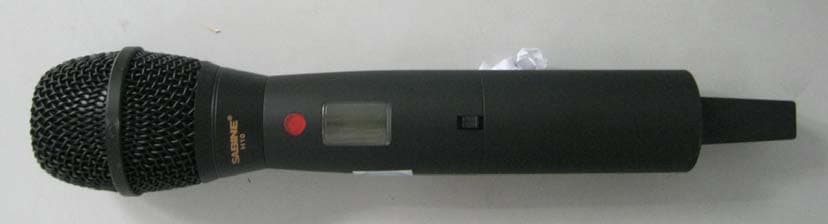
QYXSW40-H
Aug 25, 2011Handheld Transmitter
Equipment Class
DXX - Part 15 Low Power Communication Device Transmitter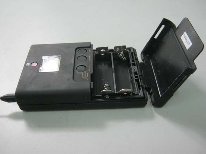
QYXSW45-T
Aug 25, 2011Bodypack Transmitter
Equipment Class
DXX - Part 15 Low Power Communication Device Transmitter
QYXSW70-HD3
Apr 29, 2003Handheld Microphone
Equipment Class
DXX - Part 15 Low Power Communication Device Transmitter