QZE1002.4GHz/5GHz Mini-PCI Module For Access Point
Juniper Networks, Inc.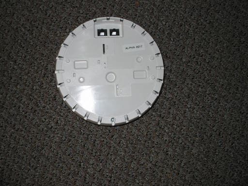
Click to zoom
Application Details
- Equipment Class
- NII - Unlicensed National Information Infrastructure TX
- Date of Grant
- Jul 08, 2003
- Application Purpose
- Original Equipment
- Date of Application
- Jul 08, 2003
- Equipment Note
- 2.4GHz/5GHz Mini-PCI Module For Access Point
- Frequency Range
- 5260.00000000 - 5320.00000000
- Company
- Juniper Networks, Inc.
- Country
- United States
Documents & Files
Document Text
Text extracted from the exhibit documents filed with the FCC. Open a document above to read the original.
Users Manual
Part Number: 730-9502-0001, Rev.1 Trapeze Mobility Point™ Installation Guide Release: 1.0 Alpha ii Trapeze Networks, the Trapeze Networks logo, the Trapeze Networks flyer icon, Mobility System, Mobility Exchange, MX, Mobility Point, MP, Mobility System Software, and RingMaster are trademarks of Trapeze Networks, Inc. All other products and services are trademarks, registered trademarks, service marks, or registered service marks of their respective owners. © 2003 Trapeze Networks, Inc. All rights reserved. Trapeze Networks, Inc. 5753 W. Las Positas Blvd. Pleasanton, CA 94588 Tel: 925-474-2200 Fax: 925-251-0642 www.trapezenetworks.com Customer Service iii Customer Service For information and documentation about Trapeze Networks Mobility System products, go to www.trapezenetworks.com . For technical support, call or send email to the Trapeze Networks Technical Assistance Center (TAC). Contacting the Technical Assistance Center To contact the Trapeze Networks Technical Assistance Center (TAC): zCall 1-866-TRPZTAC (1-866-877-9822) from any location in the United States. zCall +1 925-474-2400 from locations outside the United States. zSend email to [email protected]. Be sure to have information about your product and the problem available when you call or write. In a Network Emergency If your Trapeze Networks Mobility System network fails, call either support telephone number 24 hours a day, 7 days a week. For All Other Problems For problems other than network emergencies, call either support telephone number during regular business hours—between 8 a.m. and 6 p.m. Pacific Time (GMT–8). Or send email to [email protected] . You can expect a response within the next business day. Information TAC Needs about Your Product Have the following information available when you call or write to TAC for technical assistance: zProduct name, model, and serial number zSoftware version and release number zAny software or hardware options you purchased zType of computer you are using zDescription of the problem and any relevant data Information TAC Needs about Your Product Trapeze Mobility Point Installation Guide iv Contents v Contents Chapter 1 Introducing the Trapeze Networks Mobility System . . . . 1 Trapeze Networks Mobility System . . . . . . . . . . . . . . . . . . . . . . . . . . . . . . . . . . . . . . . . . . . . . . . . . . 1 Documentation . . . . . . . . . . . . . . . . . . . . . . . . . . . . . . . . . . . . . . . . . . . . . . . . . . . . . . . . . . . . . . . . . . 2 Documentation Conventions . . . . . . . . . . . . . . . . . . . . . . . . . . . . . . . . . . . . . . . . . . . . . . . . . . . . 2 Safety and Advisory Notices . . . . . . . . . . . . . . . . . . . . . . . . . . . . . . . . . . . . . . . . . . . . . . . . . 2 Text and Syntax Conventions . . . . . . . . . . . . . . . . . . . . . . . . . . . . . . . . . . . . . . . . . . . . . . . . 3 Chapter 2 MP Overview . . . . . . . . . . . . . . . . . . . . . . . . . . . . . . 5 Mobility Point Model Numbers . . . . . . . . . . . . . . . . . . . . . . . . . . . . . . . . . . . . . . . . . . . . . . . . . . . . . 5 External Hardware Features . . . . . . . . . . . . . . . . . . . . . . . . . . . . . . . . . . . . . . . . . . . . . . . . . . . . . . . . 6 Cable Ports . . . . . . . . . . . . . . . . . . . . . . . . . . . . . . . . . . . . . . . . . . . . . . . . . . . . . . . . . . . . . . . . . . 6 Mounting Hardware . . . . . . . . . . . . . . . . . . . . . . . . . . . . . . . . . . . . . . . . . . . . . . . . . . . . . . . . . . . 7 Status LEDs . . . . . . . . . . . . . . . . . . . . . . . . . . . . . . . . . . . . . . . . . . . . . . . . . . . . . . . . . . . . . . . . . 8 Connection Options . . . . . . . . . . . . . . . . . . . . . . . . . . . . . . . . . . . . . . . . . . . . . . . . . . . . . . . . . . . . . . 9 Single Connection to an MX Switch . . . . . . . . . . . . . . . . . . . . . . . . . . . . . . . . . . . . . . . . . . . . . 10 Dual-Homed Connection to an MX Switch . . . . . . . . . . . . . . . . . . . . . . . . . . . . . . . . . . . . . . . . 10 Dual-Homed Connection to Two MX Switches . . . . . . . . . . . . . . . . . . . . . . . . . . . . . . . . . . . . 10 Chapter 3 Installing an MP . . . . . . . . . . . . . . . . . . . . . . . . . . . 13 Unpacking an MP . . . . . . . . . . . . . . . . . . . . . . . . . . . . . . . . . . . . . . . . . . . . . . . . . . . . . . . . . . . . . . . 13 Installation Requirements and Recommendations . . . . . . . . . . . . . . . . . . . . . . . . . . . . . . . . . . . . . . 14 MX Switch Recommendation . . . . . . . . . . . . . . . . . . . . . . . . . . . . . . . . . . . . . . . . . . . . . . . . . . 14 Radio Safety Advisories . . . . . . . . . . . . . . . . . . . . . . . . . . . . . . . . . . . . . . . . . . . . . . . . . . . 15 Cable Requirements . . . . . . . . . . . . . . . . . . . . . . . . . . . . . . . . . . . . . . . . . . . . . . . . . . . . . . . . . . 16 Installation Hardware and Tools . . . . . . . . . . . . . . . . . . . . . . . . . . . . . . . . . . . . . . . . . . . . . . . . 17 Installing an MP . . . . . . . . . . . . . . . . . . . . . . . . . . . . . . . . . . . . . . . . . . . . . . . . . . . . . . . . . . . . . . . . 18 Suspended Ceiling Installation—Flush Ceiling Tiles . . . . . . . . . . . . . . . . . . . . . . . . . . . . . . . . 18 Suspended Ceiling Installation—Drop Ceiling Tiles . . . . . . . . . . . . . . . . . . . . . . . . . . . . . . . . . 22 Junction Box Installation . . . . . . . . . . . . . . . . . . . . . . . . . . . . . . . . . . . . . . . . . . . . . . . . . . . . . . 25 Solid Wall or Ceiling Installation . . . . . . . . . . . . . . . . . . . . . . . . . . . . . . . . . . . . . . . . . . . . . . . 27 Tabletop Installation . . . . . . . . . . . . . . . . . . . . . . . . . . . . . . . . . . . . . . . . . . . . . . . . . . . . . . . . . 30 Verifying MP Health . . . . . . . . . . . . . . . . . . . . . . . . . . . . . . . . . . . . . . . . . . . . . . . . . …
Text truncated - open the document above for the full version.
Cover Letter(s)
From: Anne Liang Sent: Tuesday, July 08, 2003 3:17 PM To: Mike Kuo Cc: CLIENT ADVOCATES; Steve Cheng; Michael Heckrotte Subject: RE: Trapeze Networks, Inc., FCC ID:QZE100, AN03T2912/14 ( DTS and UNII ) Hi, Mike, Question #1: A. Limited module approval is requested as per attached Modular Characteristic letter; B. Client confirms that OEM and end user installation is prohibited as indicated in the Modular Characteristic letter; C. Please see attached Modular Characteristic letter; D. Different FCC ID labels will be used for different configurations. Please refer to Modular Characteristic letter for details. Question #2: Internal photos with metal shield taken off, please see attached; Question #3: Antenna positions: please refer to attached file; Question #4: Antenna specification sheet is attached; Question #5: Theory of operation is revised to address 15.407(c). Please see attached; Question #6: Frequency stability test result is attached. -----Original Message----- From: CERTADM Sent: Thursday, July 03, 2003 2:22 PM To: '[email protected]' Subject: Trapeze Networks, Inc., FCC ID:QZE100, AN03T2912/14 ( DTS and UNII ) Notice_content ------------- Question #1: Based upon the description of equipment under test listed in the test report, it looks like you are seeking module approval to be used in the Access Point. In reviewing the attachments submitted under assessment no:AN03T2912 ( DTS ) and AN03T2914 ( UNII ) and with the information listed the user manual, please considering the following statements : A. Test Setup: based upon the test setup photos, this composite transmitter module was tested inside the access point which is not qualified for full module approval. Only limited module approval will be granted. B. Since there is no OEM installation instruction provided, this limited module approval will be limited to be installed by the applicant only. OEM and end user installation is prohibited. C. If limited module approval is desired, please provide a cover letter to request for limited module approval and address all 8 criteria per FCC public notice DA 00-1407. D. Based upon the description of user manual, one access point can have max. of two radio transmitters. Both radio transmitters are identical to each other. This radio is 802.11 a/b mini-PCI module. By default, the radio is disable. Radio characteristics can only be enabled and managed via Trapeze MX switch. Once the radio(s) is /are installed in the access point, the access point can be marketed in the following configuration : with one radio : Model No:MP-101. The radio can be configured as 802.11 b or 802.11a radio. With two radios: Model No:MP-122. One of radio can be configured as 802.11a and the other radio can be configured as 802.11b. With above information in mind, please allow me to point out the marketing requirements per FCC instruction. I) when only one radio is installed in the access point, the access point shall be labeled as "this device contains FCC ID:QZE100" II) when two radios are installed in the access point, the access point shall be labeled as " this device contains two FCC ID:QZE100". The radio module used in Trapeze access point shall be identical to the one contains in this file. Regardless 802.11b or 802.11a or 802.11 a/b functions are enable from Trapeze MX switch, no depopulation of any components are allowed. Question #2: Please provide additional internal photos of transmitter module by removing the metal plane. Question #3: Please indicate the antenna location on the internal photos. Question #4: Please provide antenna specification sheet. Question #5: Please point out which section in the theory of operation addressed the requirement of section 15.407( c ). Question #6: Please point out which section in the theory of operation addressed the requirement of section 15.407(g). Best Regards Mike Kuo The items indicated above must be submitted before processing can continue on the above referenced application. Failure to provide the requested information within 60 days of the original e-mail date may result in application dismissal and forfeiture of the filing fee. Also, please note that partial responses increase processing time and should not be submitted. Any questions about the content of this correspondence should be directed to the e-mail address listed below the name of the sender.
Cover Letter(s)
TRAPEZE NETWORKS FCC ID: QZE100 Request for transmitter modular approval Transmitter Module Characteristics Item Requirements EUT 1 Have its own RF shielding Device is equipped with Metal shielding to cover RF section. Refer to external photos 2 Have buffered modulation/data inputs (if such inputs are provided), All inputs to the modules are buffered through logic or microprocessor inputs. It is integrated in chip AR5211. 3 Have it own power supply regulation The chips IF converter and RF/IF converter which will influence the frequency radiation, have to be 2.5V DC powered. The mini-pci interface provides 3.3VDC, so there are regulators in front of these chips, the part number of this regulator is SC6204B252MR. 4 Meet the antenna requirements of Section 15.203 Device is equipped with unique antenna (u.FL(v)-LP-040) connector. Refer to external photos 5 Be tested in a stand-alone configuration, i.e., the antenna, AC or DC power and data input/output lines must be connected to the module but, the module must not be inside another case during testing Device was tested inside the access point for limited modular approval. Refer to setup photos. 6 Be labeled with its own FCC ID number, and if the FCC ID is not visible when the module is installed inside another device, then the outside of the device into which the module is installed must also display a label referring to the enclosed module. The device is labeled with FCC ID: QZE100. I) When only one radio is installed in the access point, the access point will be labeled as "this device contains FCC ID: QZE100" II) When two radios are installed in the access point, the access point shall be labeled as " this device contains two FCC ID: QZE100". 7 The modular transmitter is manufactured so that the user cannot influence the operation of the transmitter that will operate outside of the scope of the regulations. The device is to be installed by the applicant (Trapeze) only. OEM and end user installation is prohibited. 8 Address compliance with the Commission's RF exposure limits in Sections 1.1310 and 2.1093. In addition, spread spectrum transmitters operating 20cm separation distance is maintained, which satisfies mobile category requirement. RF exposure is taken care by MPE calculation. under Section 15.247 are required to address RF exposure compliance in accordance with Section 15.247(b)(4).
ID Label/Location Info
PROPOSED FCC ID LABEL AND LOCATION TRAPEZE NETWORKS, INC. This device complies with Part 15 of the FCC Rules. Operation is subject to the following two conditions: (1) this device may not cause harmful interference, and (2) this device must accept any interference received, including interference that may cause undesired operation. FCC ID: QZE100 FCC ID LABEL LOCATION
Internal Photos
Trapeze 03U1984 Antenna Position Antenna
Parts List/Tune Up Info
Bluetooth TM /802.11 a & b Antenna______ Part Number 100961 Features: Description: * Wide bandwidth and high gain in a compact size The 100961 is a surface-mount dual- * Enhanced hemispherical pattern improves RF link band antenna intended for use in reliability of portable devices. Bluetooth, 802.11a and 802.11 b * Surface-mount design available in tape-and-reel applications. This antenna provides packaging for low-cost automated pick-and-place excellent performance at a low cost. assembly. Specifications: Contact Information: Frequency Range (MHz): 2400-2500 MHz Tyco Electronics 5100-5900 MHz 9565 Soquel Drive Peak Gain: >+2dBi Aptos, CA 95003 VSWR: <2.5 : 1 Polarization: Linear Phone: 831.661.4200 Powerhandling: 10-watt cw Fax: 831.661.4201 Feedpoint Impedance: 50 Ohms Web: http://antenna.tycoelctronics.com Weight: <1g Dimensions: Height 6mm Diameter 16mm Mounting: Antenna Testing Orientation: Azimuth Plot (Total Gain): Elevation 1 (Total Gain): Elevation 2 (Total Gain):
RF Exposure Info
REPORT NO: 03U1984-1B DATE: JUNE 11, 2003 EUT: DUAL MODE 2.4GHz / 5GHz MODULE FOR ACCESS POINT FCC ID: QZE100 Page 24 of 74 COMPLIANCE CERTIFICATION SERVICES DOCUMENT NO: CCSUP4031A 561F MONTEREY ROAD, MORGAN HILL, CA 95037 USA TEL: (408) 463-0885 FAX: (408) 463-0888 This report shall not be reproduced except in full, without the written approval of CCS. This document may be altered or revised by Compliance Certification Services personnel only, and shall be noted in the revision section of the document. 6.3. MAXIMUM PERMISSIBLE EXPOSURE LIMITS §15.247 (b) (5) Systems operating under the provisions of this section shall be operated in a manner that ensures that the public is not exposed to radio frequency energy levels in excess of the Commission's guidelines. See §1.1307(b)(1) of this chapter. CALCULATIONS Given E = √ (30 * P * G) / d and S = E ^ 2 / 3770 where E = Field Strength in Volts / meter P = Power in Watts G = Numeric antenna gain d = distance in meters S = Power Density in milliwatts / square centimeter Combining equations and rearranging the terms to express the distance as a function of the remaining variables yields: d = √ ((30 * P * G) / (3770 * S)) Changing to units of mW and cm, using: P (mW) = P (W) / 1000 and d (cm) =100 * d (m) yields d = 100 * √ ((30 * (P / 1000) * G) / (3770 * S)) d = 0.282 * √ (P * G / S) where d = distance in cm P = Power in mW G = Numeric antenna gain S = Power Density in mW / cm^2 REPORT NO: 03U1984-1B DATE: JUNE 11, 2003 EUT: DUAL MODE 2.4GHz / 5GHz MODULE FOR ACCESS POINT FCC ID: QZE100 Page 25 of 74 COMPLIANCE CERTIFICATION SERVICES DOCUMENT NO: CCSUP4031A 561F MONTEREY ROAD, MORGAN HILL, CA 95037 USA TEL: (408) 463-0885 FAX: (408) 463-0888 This report shall not be reproduced except in full, without the written approval of CCS. This document may be altered or revised by Compliance Certification Services personnel only, and shall be noted in the revision section of the document. Substituting the logarithmic form of power and gain using: P (mW) = 10 ^ (P (dBm) / 10) and G (numeric) = 10 ^ (G (dBi) / 10) yields d = 0.282 * 10 ^ ((P + G) / 20) / √ S Equation (1) where d = MPE distance in cm P = Power in dBm G = Antenna Gain in dBi S = Power Density Limit in mW / cm^2 Equation (1) and the measured peak power is used to calculate the MPE distance. LIMITS S = 1.0 mW / cm^2 from 1.1310 Table 1 NOTE: For mobile or fixed location transmitters, the minimum separation distance is 20 cm, even if calculations indicate that the MPE distance would be less. RESULTS No non-compliance noted: ModePower Density LimitOutput PowerAntenna GainMPE Distance (mW/cm^2)(dBm)(dBi)(cm) 802.11a1.013.772.001.73
Test Report
FCC CFR47 PART 15 SUBPART E CERTIFICATION TEST REPORT FOR DUAL MODE 2.4GHz / 5GHz MODULE FOR ACCESS POINT MODEL NUMBER: 100 RADIO CARD FOR MOBILITY POINT 100/101/122 BRAND NAME: TRAPEZE NETWORKS, INC. FCC ID: QZE100 REPORT NUMBER: 03U1984-1B ISSUE DATE: JUNE 11 TH , 2003 Prepared for TRAPEZE NETWORKS, INC. 5753 W. LAS POSITAS BLVD. PLEASANTON, CALIFORNIA 94588 U.S.A Prepared by COMPLIANCE CERTIFICATION SERVICES 561F MONTEREY ROAD, MORGAN HILL, CA 95037, USA TEL: (408) 463-0885 FAX: (408) 463-0888 REPORT NO: 03U1984-1B DATE: JUNE 11, 2003 EUT: DUAL MODE 2.4GHz / 5GHz MODULE FOR ACCESS POINT FCC ID: QZE100 Page 2 of 74 COMPLIANCE CERTIFICATION SERVICES DOCUMENT NO: CCSUP4031A 561F MONTEREY ROAD, MORGAN HILL, CA 95037 USA TEL: (408) 463-0885 FAX: (408) 463-0888 This report shall not be reproduced except in full, without the written approval of CCS. This document may be altered or revised by Compliance Certification Services personnel only, and shall be noted in the revision section of the document. TABLE OF CONTENTS 1. TEST RESULT CERTIFICATION.................................................................................................3 2. EUT DESCRIPTION.........................................................................................................................4 3. TEST METHODOLOGY..................................................................................................................5 4. FACILITIES AND ACCREDITATION..........................................................................................5 4.1. FACILITIES AND EQUIPMENT.................................................................................................5 4.2. TABLE OF ACCREDITATIONS AND LISTINGS........................................................................6 5. CALIBRATION AND UNCERTAINTY.........................................................................................7 5.1. MEASURING INSTRUMENT CALIBRATION............................................................................7 5.2. MEASUREMENT UNCERTAINTY..............................................................................................7 5.3. TEST AND MEASUREMENT EQUIPMENT...............................................................................8 6. SETUP OF EQUIPMENT UNDER TEST.......................................................................................8 6. SETUP OF EQUIPMENT UNDER TEST.......................................................................................9 6.1. EMISSION BANDWIDTH..........................................................................................................13 6.2. PEAK POWER............................................................................................................................18 6.3. MAXIMUM PERMISSIBLE EXPOSURE...................................................................................24 6.4. AVERAGE POWER....................................................................................................................26 6.5. PEAK POWER SPECTRAL DENSITY.......................................................................................27 6.6. PEAK EXCURSION...................................................................................................................33 6.7. TRANSMISSION IN THE ABSENCE OF DATA........................................................................38 6.8. TYPE OF ANTENNA..................................................................................................................38 6.9. FREQUENCY STABILITY..........................................................................................................38 6.10. CONDUCTED UNDESIRABLE EMISSIONS........................................................................39 6.11. RADIATED EMISSIONS........................................................................................................44 6.12. POWERLINE CONDUCTED EMISSIONS............................................................................66 6.13. SETUP PHOTOS........................................................................................................................69 REPORT NO: 03U1984-1B DATE: JUNE 11, 2003 EUT: DUAL MODE 2.4GHz / 5GHz MODULE FOR ACCESS POINT FCC ID: QZE100 Page 3 of 74 COMPLIANCE CERTIFICATION SERVICES DOCUMENT NO: CCSUP4031A 561F MONTEREY ROAD, MORGAN HILL, CA 95037 USA TEL: (408) 463-0885 FAX: (408) 463-0888 This report shall not be reproduced except in full, without the written approval of CCS. This document may be altered or revised by Compliance Certification Services personnel only, and shall be noted in the revision section of the document. 1. TEST RESULT CERTIFICATION COMPANY NAME: TRAPEZE NETWORKS, INC. 5753 W. LAS POSITAS BLVD. PLEASANTON, CA 94588, U.S.A EUT DESCRIPTION: DUAL MODE 2.4GHz / 5GHz MODULE FOR ACCESS POINT MODEL: 100 RADIO CARD FOR MOBILITY POINT 100/101/102 DATE TESTED: MAY 7 – JUNE 10, 2003 APPLICABLE STANDARDS STANDARD TEST RESULTS FCC PART 15 SUBPART E NO NON-COMPLIANCE NOTED Compliance Certification Services, Inc. tested the above equipment in accordance with the requirements set forth in the above standards. The test results show that the equipment tested is capable of demonstrating compliance with the requirements as documented in this report. Note: This document reports conditions under which testing was conducted and results of tests performed. This document may not be altered or revised in any way unless done so by Compliance Certification Services and all revisions are duly noted in the revisions section. Any alteration of this document not carried out by Compliance Certification Services will constitute fraud and shall nullify the document. Note: The 5.2 GHz band is applicable to this report; other bands of operation (2.4 and 5.8 GHz) are documented in a separate report. Approved & Released For CCS By: Tested By: MIKE HECKROTTE NEELESH RAJ CHIEF ENGINEER EMC ENGINEER COMPLIANCE CERTIFICATION…
Text truncated - open the document above for the full version.
Test Report
REPORT NO: 03U1984-1B DATE: JUNE 11, 2003 EUT: DUAL MODE 2.4GHz / 5GHz MODULE FOR ACCESS POINT FCC ID: QZE100 Page 36 of 74 COMPLIANCE CERTIFICATION SERVICES DOCUMENT NO: CCSUP4031A 561F MONTEREY ROAD, MORGAN HILL, CA 95037 USA TEL: (408) 463-0885 FAX: (408) 463-0888 This report shall not be reproduced except in full, without the written approval of CCS. This document may be altered or revised by Compliance Certification Services personnel only, and shall be noted in the revision section of the document. REPORT NO: 03U1984-1B DATE: JUNE 11, 2003 EUT: DUAL MODE 2.4GHz / 5GHz MODULE FOR ACCESS POINT FCC ID: QZE100 Page 37 of 74 COMPLIANCE CERTIFICATION SERVICES DOCUMENT NO: CCSUP4031A 561F MONTEREY ROAD, MORGAN HILL, CA 95037 USA TEL: (408) 463-0885 FAX: (408) 463-0888 This report shall not be reproduced except in full, without the written approval of CCS. This document may be altered or revised by Compliance Certification Services personnel only, and shall be noted in the revision section of the document. REPORT NO: 03U1984-1B DATE: JUNE 11, 2003 EUT: DUAL MODE 2.4GHz / 5GHz MODULE FOR ACCESS POINT FCC ID: QZE100 Page 38 of 74 COMPLIANCE CERTIFICATION SERVICES DOCUMENT NO: CCSUP4031A 561F MONTEREY ROAD, MORGAN HILL, CA 95037 USA TEL: (408) 463-0885 FAX: (408) 463-0888 This report shall not be reproduced except in full, without the written approval of CCS. This document may be altered or revised by Compliance Certification Services personnel only, and shall be noted in the revision section of the document. 6.7. TRANSMISSION IN THE ABSENCE OF DATA RESULTS No non-compliance noted: See theory of operation 6.8. TYPE OF ANTENNA RESULTS No non-compliance noted: Antenna is integral. 6.9. FREQUENCY STABILITY RESULTS No non-compliance noted: Referring to the theory of operation, the crystal used to set the frequency has a temperature coefficient of +/- 20 ppm over the specified rated temperature range. For a transmitter fundamental frequency of 5.35 GHz, this corresponds to +/- 107 kHz. REPORT NO: 03U1984-1B DATE: JUNE 11, 2003 EUT: DUAL MODE 2.4GHz / 5GHz MODULE FOR ACCESS POINT FCC ID: QZE100 Page 39 of 74 COMPLIANCE CERTIFICATION SERVICES DOCUMENT NO: CCSUP4031A 561F MONTEREY ROAD, MORGAN HILL, CA 95037 USA TEL: (408) 463-0885 FAX: (408) 463-0888 This report shall not be reproduced except in full, without the written approval of CCS. This document may be altered or revised by Compliance Certification Services personnel only, and shall be noted in the revision section of the document. 6.10. CONDUCTED UNDESIRABLE EMISSIONS LIMITS §15.407 (b) (1 & 2) For transmitters operating in the 5.15-5.35 GHz band: all emissions outside of the 5.15-5.35 GHz band shall not exceed an EIRP of -27dBm / MHz. TEST PROCEDURE Conducted RF measurements of the transmitter output are made to confirm that the EUT antenna port conducted emissions meet the specified limit and to identify any spurious signals that require further investigation or measurements on the radiated emissions site. The transmitter output is connected to the spectrum analyzer. The resolution bandwidth is set to 1 MHz. The video bandwidth is set to 1 MHz. Peak detection measurements are compared to the average EIRP limit, adjusted for the maximum antenna gain. If necessary, additional average detection measurements are made. Measurements are made over the 30 MHz to 40 GHz range with the transmitter set to the lowest, middle, and highest channels. RESULTS No non-compliance noted: REPORT NO: 03U1984-1B DATE: JUNE 11, 2003 EUT: DUAL MODE 2.4GHz / 5GHz MODULE FOR ACCESS POINT FCC ID: QZE100 Page 40 of 74 COMPLIANCE CERTIFICATION SERVICES DOCUMENT NO: CCSUP4031A 561F MONTEREY ROAD, MORGAN HILL, CA 95037 USA TEL: (408) 463-0885 FAX: (408) 463-0888 This report shall not be reproduced except in full, without the written approval of CCS. This document may be altered or revised by Compliance Certification Services personnel only, and shall be noted in the revision section of the document. CONDUCTED SPURIOUS EMISSIONS (BASE MODE) (channel 5180 MHz) REPORT NO: 03U1984-1B DATE: JUNE 11, 2003 EUT: DUAL MODE 2.4GHz / 5GHz MODULE FOR ACCESS POINT FCC ID: QZE100 Page 41 of 74 COMPLIANCE CERTIFICATION SERVICES DOCUMENT NO: CCSUP4031A 561F MONTEREY ROAD, MORGAN HILL, CA 95037 USA TEL: (408) 463-0885 FAX: (408) 463-0888 This report shall not be reproduced except in full, without the written approval of CCS. This document may be altered or revised by Compliance Certification Services personnel only, and shall be noted in the revision section of the document. (channel 5240 MHz) REPORT NO: 03U1984-1B DATE: JUNE 11, 2003 EUT: DUAL MODE 2.4GHz / 5GHz MODULE FOR ACCESS POINT FCC ID: QZE100 Page 42 of 74 COMPLIANCE CERTIFICATION SERVICES DOCUMENT NO: CCSUP4031A 561F MONTEREY ROAD, MORGAN HILL, CA 95037 USA TEL: (408) 463-0885 FAX: (408) 463-0888 This report shall not be reproduced except in full, without the written approval of CCS. This document may be altered or revised by Compliance Certification Services personnel only, and shall be noted in the revision section of the document. (channel 5260 MHz) REPORT NO: 03U1984-1B DATE: JUNE 11, 2003 EUT: DUAL MODE 2.4GHz / 5GHz MODULE FOR ACCESS POINT FCC ID: QZE100 Page 43 of 74 COMPLIANCE CERTIFICATION SERVICES DOCUMENT NO: CCSUP4031A 561F MONTEREY ROAD, MORGAN HILL, CA 95037 USA TEL: (408) 463-0885 FAX: (408) 463-0888 This report shall not be reproduced except in full, without the written approval of CCS. This document may be altered or revised by Compliance Certification Services personnel only, and shall be noted in the revision section of the document. (channel 5230 MHz) REPORT NO: 03U1984-1B DATE: JUNE 11, 2003 EUT: DUAL MODE 2.4GHz / 5GHz MODULE FOR ACCESS POINT FCC ID: QZE100 Page 44 of 74 COMPLIANCE CERTIFICATION SERVICES DOCUMENT NO: CCSUP4031A 561F MONTEREY ROAD, MORGAN HILL, CA 95037 USA TEL: (408) 463-0885 FAX: (408) 463-0888 This report shall not be reproduced except in full, without the written approval of CCS. This do…
Text truncated - open the document above for the full version.
Test Setup Photos
REPORT NO: 03U1984-1B DATE: JUNE 11, 2003 EUT: DUAL MODE 2.4GHz / 5GHz MODULE FOR ACCESS POINT FCC ID: QZE100 Page 69 of 74 COMPLIANCE CERTIFICATION SERVICES DOCUMENT NO: CCSUP4031A 561F MONTEREY ROAD, MORGAN HILL, CA 95037 USA TEL: (408) 463-0885 FAX: (408) 463-0888 This report shall not be reproduced except in full, without the written approval of CCS. This document may be altered or revised by Compliance Certification Services personnel only, and shall be noted in the revision section of the document. 6.13. SETUP PHOTOS ANTENNA PORT CONDUCTED RF MEASUREMENT SETUP REPORT NO: 03U1984-1B DATE: JUNE 11, 2003 EUT: DUAL MODE 2.4GHz / 5GHz MODULE FOR ACCESS POINT FCC ID: QZE100 Page 70 of 74 COMPLIANCE CERTIFICATION SERVICES DOCUMENT NO: CCSUP4031A 561F MONTEREY ROAD, MORGAN HILL, CA 95037 USA TEL: (408) 463-0885 FAX: (408) 463-0888 This report shall not be reproduced except in full, without the written approval of CCS. This document may be altered or revised by Compliance Certification Services personnel only, and shall be noted in the revision section of the document. RADIATED RF MEASUREMENT SETUP REPORT NO: 03U1984-1B DATE: JUNE 11, 2003 EUT: DUAL MODE 2.4GHz / 5GHz MODULE F…
Text truncated - open the document above for the full version.
Contact Information
Applicant
Mark Gandler(Sr. Manager Compliance Engineering)
Test Firm
Compliance Certification Services IncSteve Cheng
Technical Specifications
| # | Rule Parts | Frequency Range | Power Output |
|---|---|---|---|
| 2 | 15E | 5.26 GHz - 5.32 GHz | 24.00 mW |
Other Applications from Juniper Networks, Inc.
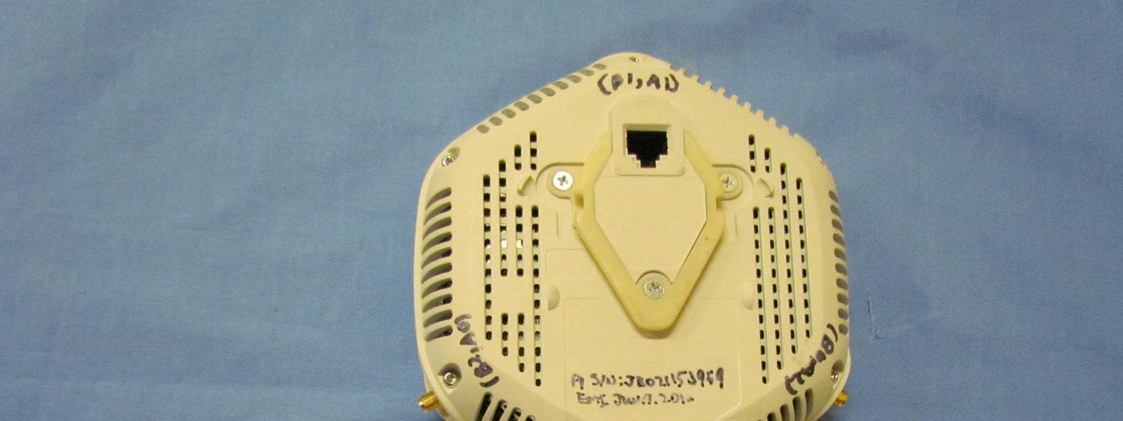
QZEWLA532E
Oct 31, 2012WLA532E Wireless LAN Access Point
Equipment Class
NII - Unlicensed National Information Infrastructure TX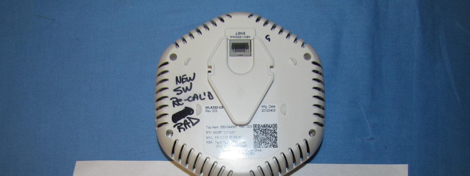
QZEWLA322
Jun 10, 2012WLA322 Wireless LAN Access Point
Equipment Class
NII - Unlicensed National Information Infrastructure TX
QZEWLA321
Apr 01, 2012WLA321 Wireless LAN Access Point
Equipment Class
NII - Unlicensed National Information Infrastructure TX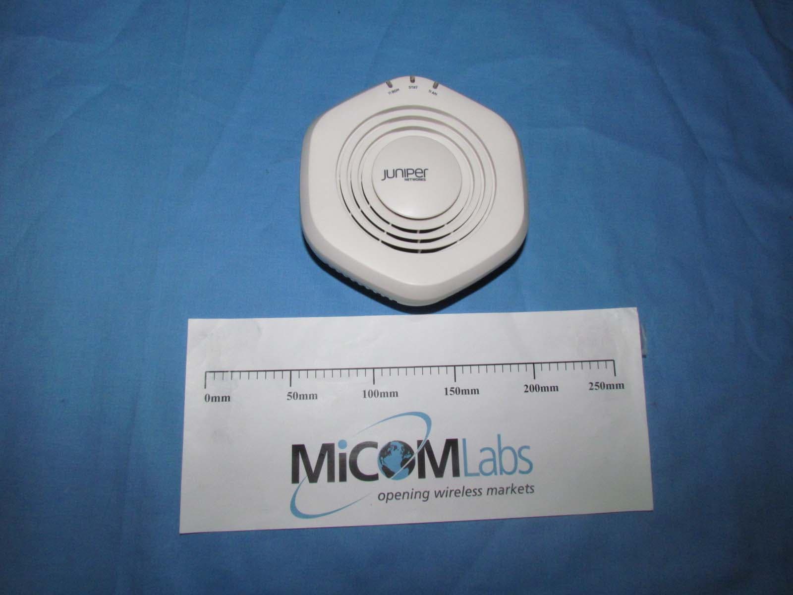
QZEWLA532
Nov 16, 2011WLA532 Wirelesss LAN Access Point
Equipment Class
DTS - Digital Transmission System
QZE520
Jul 14, 2010Enterprise Access Point
Equipment Class
DTS - Digital Transmission System