QZEWLA532EWLA532E Wireless LAN Access Point
Juniper Networks, Inc.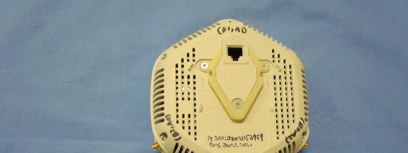
Click to zoom
Application Details
- Equipment Class
- NII - Unlicensed National Information Infrastructure TX
- Date of Grant
- Oct 31, 2012
- Application Purpose
- Original Equipment
- Date of Application
- Oct 25, 2012
- Equipment Note
- WLA532E Wireless LAN Access Point
- Frequency Range
- 5190.00000000 - 5230.00000000
- Company
- Juniper Networks, Inc.
- Country
- United States
Documents & Files
Document Text
Text extracted from the exhibit documents filed with the FCC. Open a document above to read the original.
Users Manual
WLA532E Access Point Quick StartSee the complete Wireless LAN Services (WLS) product documentation at http://www.juniper.net/techpubs/en_US/r elease-independent/wireless/information- products/pathway-pages/wireless-lan/index.html.Before you begin installing the Juniper Networks WLA532E Wireless LAN Access Point, read the planning instructions in the Wire less LAN Services (WLS) documentation at http://www.juniper.net/techp ubs/en_US/release-independent/ wireless/information-produ cts/pathway-pages/wla-series/wla532e/wla532e.ht ml to make sure that the site meets power, environmental, and clearance requirements for the access point.To install the access point on a ceiling-tile rail and to connect the access point, you need: One ceiling-mount bracket (WLA-BRKT-CLNG) (provided) Mounting template (provided) Category 5e straight-through signaling cable with RJ-45 connectors, installed (not provided) Three supported external omnidirectio nal and paddle antennas (not provided) Box cutter or similar tool to cu t the ceiling tile (not provided) (Optional) An indoor ceiling-rail adapter an d a legacy adapter (both provided), which are needed only for unique ceiling-rail installations using the adapters-see the WLA532E Access Point Hardware Documentation at http://www.juniper.net/tec hpubs/en_US/release-independ ent/wireless/information- products/pathway-pages/wireless-lan/index.html. (Optional) Security kit, which includes a secu rity tool and a security screw. (The kit is not provided and can be ordered separately.) Part 1: Connect External Antennas1. Attach three supported external omnidirectional and paddle antennas to the external antenna ports of the access point. For antenna specifications and ordering information see the WLA Series Wireless LA N Access Points product information at http://www.juniper.net/u s/en/products-services/ wireless/wla-series. 2. Orient the antennas for the best antenna reception.Part 2: Install the Access Point1. Select an installation location under a rece ssed 9/16-inch or 15/16-inch T ceiling-tile rail in the ceiling. 2. Cut a hole as follows in the ceiling tile for running the Category 5e cable: − Place the mounting template over the area where you will install the access point. − Use a box cutter or a similar tool to cut along the line marking the opening for the port connectors. − Remove the mounting template and the material you cut from the ceiling tile. 3. Run the Category 5e cable from the ceiling through the hole in the ceiling tile. 4. Ensure that the snaps on the top of the ce iling-mount bracket are open so that the clips can fully extend to fit around the ceiling rail. The bracket is shipped with the snaps open so that it is ready to be clipped over a ceiling rail. 5. If the snaps are closed, open the snaps by pressing in and up with your thumbs on both sides of the snaps on the bottom of the bracket until the snaps are fully open. 6. With the bracket clips full y extended, align the clips with the rail and hook the clips around the top sides of the rail. Push in on the sides of the bracket until the clips lock over the rail. Listen for a click that indica tes that the clips have locked. Ensure that the bracket has locked over the rail by gently pulling down on the bracket before installing the access point. 7. Grasp the Category 5e cable that extends from the ceiling and plug it into the access point. 8. Align the access point with the bracket. Push in Push in Juniper Networks, Junos, Steel-Belted Radius , NetScreen, and ScreenOS are registered trademarks of Juniper Networks, Inc. in th e United States and other countries. The Juniper Networks Logo, the Junos logo, and JunosE are trademarks of Juniper Networks, Inc. All other trademarks, serv ice marks, registered trademarks, or registered service marks ar e the property of their respective owners. Juniper Ne tworks assumes no responsibility for any inaccuracies in this document. Juniper Networks reserves the right to change , modify, transfer, or otherwise revise this publication without notice. Products made or sold by Juniper Networks or components thereof might be covered by one or more of the following patents that are owned by or licensed to Juniper Networks: U.S. Patent Nos. 5,473,599, 5,905,725, 5,909,440, 6 ,192,051, 6,333,650, 6,359,479, 6,406,312, 6,429,706, 6,459,579, 6,493,347, 6,538,518, 6,538,899, 6,552,918, 6,567,902, 6,578,186, and 6,590,785. Copyright © 2012 Juniper Networks, Inc. All rights reserved. Part Number: 530-0 48970, Revision 01, 5 October 2012. 9. Press the access point forward until it cli cks into place. Ensure that the access point is seated correctly in the bracket by gently pulling down on the access point. 10. If the access point is not properly secure d, press the release button on top of the bracket to unlock the access point. Making sure that the cable is still connected, repeat Steps 8 and 9. NOTE: We recommend that you use the optional security kit to secure the access point (Step 11). The kit includes a security tool and a security screw. Be sure to retain the tool so you can unlock and move the access point. Never use a power tool to insert or remove the security screw.11. (Optional) To lock the access point into place using the security kit, secure the security screw in the release button by us ing the tool provided with the security kit. Do not overtighten the screw. Part 3: Connect the Access Point to a Wireless LAN ControllerAfter you install the access point, you can connec t the access point directly or indirectly to a Juniper Networks WLC Series Wireless LAN Controller (WLC) through an intermediate Layer 2 or Layer 3 network device.To connect the access point directly to a WLC:1. Insert one end of the installed Category 5e cable into the Ethernet port of the access point and the other end into t he Ethernet port of the WLC. 2. Wait for the link to be activated. The link is activated if the access point LED on the Ethernet port of the WLC i…
Text truncated - open the document above for the full version.
Cover Letter(s)
9/11/2012 Federal Communications Commission Equipment Authorization Branch 7435 Oakland Mills Road Columbia, MD 21046 Request for Confidentiality Company name: Juniper Networks, Inc. FCC ID: QZEWLA532E FCC Part 15 Certification Gentlemen, Pursuant to 47 CFR 0.457(d)(1)(ii) and 0.459 Juniper Networks, Inc. hereby requests permanent confidentiality of the following documents for the subject application: Exhibit Type Description Schematics Schematics Block Diagram Block Diagram Part List Part List Operational Description Operational Description Note: Exhibit types that are commonly held confidential are: (1) Schematics, (2) Block Diagrams, (3) Operational Descriptions, (4) Parts List / Tune UP Info. Any exhibit NOT granted confidentiality is viewable on the FCC website as soon as a grant is issued. Reason why the material should be withheld from public inspection: These documents contain detailed system, equipment description and related information about the product which Juniper Networks, Inc. considers to be proprietary, confidential, and a custom design otherwise not released to the general public. State why the information is a “trade secret;” Since the design is a basis from which future technological products will evolve, Juniper Networks, Inc. considers that this information would be of benefit to its competitors and that the disclosure of the information in these documents would give competitors an unfair advantage in the market. Trade secret” information is information which is not generally known or reasonably ascertainable, by which a business can obtain an economic advantage over competitors. The information is not normally released to any party or person outside the company. State whether the information is publicly available anywhere else: None. Sincerely, Signature: Name: Agnes Fu Title: Compliance Engineer Company: Juniper Networks, Inc. Address: 1194 North Mathilda Ave., Sunnyvale, CA 94089
Cover Letter(s)
Date: 09/11/12 FCC ID: QZEWLA532E Office of Engineering Technology Federal Communications Commission 7435 Oakland Mills Road Columbia, MD 21046 Pursuant to sections 0.407(d)(1)(ii) and 0.459 of the Commission’s rules, this letter requests confidential treatment of following material filed in support of the above- referenced application. Juniper Networks, Inc. requests the following documents be held as confidential until such time as the product is released per FCC Public Notice 04-1705. - Set up photos - Product Internal Photos - Product external photos - User manual - Product literature or description The information contained in the document presents information about Juniper Networks, Inc. product that is being certified for commercial development. If competitors were to have access to this document both before and after release, they would have knowledge of Juniper Networks, Inc. proprietary technology and would be able to use this advance knowledge to their advantage. This could result in substantial competitive harm to Juniper Networks, Inc. ability to bring future product to market, should that decision be made. 1. Identification of any measures taken by the submitting party to prevent unauthorized disclosure. a. Information about Juniper Networks, Inc. products currently under development is considered by the company to be commercially sensitive information that employees are not permitted to discuss outside the company. 2. Identification of whether the information is available to the public and the extent of any previous disclosure of information to third parties. a. Information about product development is not routinely provided to the public, and is not available on Juniper Networks, Inc.web site. No information about this product has been disclosed. 3. Justification of the period during which the submitting party asserts that material should not be available for public disclosure. a. We further authorize the release of the above information after the official product launch scheduled for 11/15/2012. Or a period not to exceed 60 days which ever comes first. This request is in addition to our request to with hold specific Juniper Networks, Inc. technology confidential for the life of the product per applicable regulations. Sincerely, Signature: Name: Agnes Fu Title: Compliance Engineer
External Photos
MiCOM Labs, 440 Boulder Court, Suite 200, Pleasanton, CA 94566 Tel: +1 (925) 462-0304, Fax: +1 (925) 462-0306, Web: www.micomlabs.com the wireless lab 23 August 2012 Juniper Networks WLA532E External Photos EUT Top Page 2 of 2 the wireless lab EUT Bottom
ID Label/Location Info
JUNIPER NETWORKS, INC. MODEL: WLA532E-US WIRELESS LAN ACCESS POINT FCC ID: QZEWLA532E P/N: 520-048861 REV01 XX MADE IN CHINA label vendor CSA ID
Internal Photos
MiCOM Labs, 440 Boulder Court, Suite 200, Pleasanton, CA 94566 Tel: +1 (925) 462-0304, Fax: +1 (925) 462-0306, Web: www.micomlabs.com the wireless lab 8 October 2012 Juniper Networks WLA532E-WW Internal Photos Installation view Page 2 of 4 the wireless lab Main Assy back Page 3 of 4 the wireless lab Main Assy back 2 Page 4 of 4 the wireless lab Main Assy front
RF Exposure Info
1.1.1. Maximum Permissible Exposure FCC, Part 15 Subpart C §15.407(f) Industry Canada RSS-Gen §5.5 Calculations for Maximum Permissible Exposure Levels Power Density = Pd (mW/cm 2 ) = EIRP/(4πd 2 ) EIRP = P * G P = Peak output power (mW) G = Antenna numeric gain (numeric) d = Separation distance (cm) Numeric Gain = 10 ^ (G (dBi)/10) Because the EUT belongs to the General Population/Uncontrolled Exposure the limit of power density is 1.0 mW/cm 2 Freq. Band (MHz) Antenna Gain (dBi) Numeric Gain (numeric) Peak Output Power (dBm) Peak Output Power (mW) Calculated Safe Distance @ 1mW/cm 2 Limit(cm) Minimum Separation Distance (cm) 5150 - 5250 10.7 11.75 +12.3 17.00 4.0 20.00 Note: for mobile or fixed location transmitters the minimum separation distance is 20cm, even if calculations indicate the MPE distance to be less. Specification Maximum Permissible Exposure Limits FCC §1.1310 Limit = 1mW / cm 2 from 1.310 Table 1 RSS-Gen §5.5 Before equipment certification is granted, the application requirements of RSS-102 shall be met. Laboratory Measurement Uncertainty for Power Measurements Measurement uncertainty ±1.33 dB
Test Report
COVER PAGE Test of Juniper Networks WLA532E Wireless LAN Access Poin t To: FCC 47 CFR Part 15.407 & IC RSS-210 Test Report Serial No.: JNIP22-U2 Rev A TITLE PAGE TEST REPORT FROM Test of Juniper Networks WLA532E Wireless LAN Access Point to To FCC 47 CFR Part 15.407 & IC RSS-210 Test Report Serial No.: JNIP22-U2 Rev A Note: this report contains data with regard to the 5,150 to 5,250 MHz band for Juniper Networks, WLA532E Wireless Access Point. 2.4 and 5.8 GHz test data are reported in MiCOM Labs test report JNIP22-U1 This report supersedes None Applicant: Juniper Networks, Inc 1194 North Mathilda Avenue Sunnyvale California 94089, USA Product F unction:Wireless Access Point Copy No: pdf Issue Date: 5th October 2012 This Test Report is Issued Under the Authority of; MiCOM Labs, Inc. 440 Boulder Cour t, Suite 200 Pleasanton, CA 94566 USA Phone: +1 (925) 462-0304 Fax: +1 (925) 462-0306 www.micomlabs.com TEST CERTIFICATE #2381.01 MiCOM Labs is an ISO 17025 Accredited Testing Laboratory This test report may be reproduced in full only. The document may only be updated by MiCOM Labs personnel. Any changes will be noted in the Document History section of the report. Title: Juniper Networks WLA532E Wireless LAN Access Point To: Serial #: Issue Date: Page: FCC 47 CF R Part 15.407 & IC RSS-210 JNIP22-U2 Rev A 5th October 2012 3 of 169 This test report may be reproduced in full only. The document may only be updated by MiCOM Labs personnel. Any changes will be noted in the Document History section of the report. MiCOM Labs, 440 Boulder Court, Suite 200, Pleasanton, CA 94566 USA, Phone: 925.462.0304, Fax: 925.462.0306, www.micomlabs.com This page has been left intentionally blank Title: Juniper Networks WLA532E Wireless LAN Access Point To: Serial #: Issue Date: Page: FCC 47 CF R Part 15.407 & IC RSS-210 JNIP22-U2 Rev A 5th October 2012 4 of 169 This test report may be reproduced in full only. The document may only be updated by MiCOM Labs p ersonnel. Any changes will be noted in the Document History section of the report. MiCOM Labs, 440 Boulder Court, Suite 200, Pleasanton, CA 94566 USA, Phone: 925.462.0304, Fax: 925.462.0306, www.micomlabs.com TABLE OF CONTENTS ACCREDITATION, LISTINGS & RECOGNITION ............................................................. 6 TESTING ACCREDITATION ..............................................................................................6 RECOGNITION ...................................................................................................................7 PRODUCT CERTIFICATION ..............................................................................................8 1. TEST RESULT CERTIFICATE.................................................................................. 10 2. REFERENCES AND MEASUREMENT UNCERTAINTY ........................................ 11 2.1. Normative References..............................................................................................11 2.2. Test and Uncertainty Procedures.............................................................................12 3. PRODUCT DETAILS AND TEST CONFIGURATIONS ........................................... 13 3.1. Technical Details ......................................................................................................13 3.2. Scope of Test Program ............................................................................................14 3.3. Equipment Model(s) and Serial Number(s) ..............................................................18 3.4. Antenna Details ........................................................................................................18 3.5. Cabling and I/O Ports ...............................................................................................18 3.6. Test Configurations ..................................................................................................19 3.7. Equipment Modifications ..........................................................................................20 3.8. Deviations from the Test Standard...........................................................................20 3.9. Subcontracted Testing or Third Party Data ..............................................................20 4. TESTING EQUIPMENT CONFIGURATION(S) ........................................................ 21 4.1. Conducted RF Emission Test Set-up .......................................................................21 4.2. Radiated Spurious Emission Test Set-up > 1 GHz ..................................................22 4.3. Digital Emissions Test Set-up (0.03 – 1 GHz)..........................................................23 4.4. ac Wireline Emission Test Set-up ............................................................................24 5. TEST SUMMARY....................................................................................................... 25 6. TEST RESULTS ........................................................................................................ 27 6.1. Device Characteristics..............................................................................................27 6.1.1. Conducted Testing ..................................................................................... 27 6.1.2. Radiated Emission Testing ........................................................................ 47 6.1.3. AC Wireline Conducted Emissions (150 kHz – 30 MHz) ........................... 87 7. PHOTOGRAPHS ....................................................................................................... 89 7.1. Conducted Test Setup .............................................................................................89 7.2. Test Setup - Digital Emissions below 1 GHz............................................................90 7.3. Radiated Emissions Test Setup >1 GHz – WLA-ANT-7360P-IN .............................91 7.4. Radiated Emissions Test Setup >1 GHz – WLA-ANT-7360…
Text truncated - open the document above for the full version.
Test Setup Photos
MiCOM Labs, 440 Boulder Court, Suite 200, Pleasanton, CA 94566 Tel: +1 (925) 462-0304, Fax: +1 (925) 462-0306, Web: www.micomlabs.com the wireless lab 23 August 2012 Juniper Networks WLA532E Test Photos Conducted Test Setup Page 2 of 5 the wireless lab Test Setup - Digital Emissions below 1 GHz Page 3 of 5 the wireless lab Radiated Emissions Test Setup >1 GHz – WLA-ANT-7360P-IN Page 4 of 5 the wireless lab Radiated Emissions Test Setup >1 GHz – WLA-ANT-7360A-OUT Page 5 of 5 the wireless lab Radiated Emissions Test Setup >1 GHz – WLA-ANT-77555-OUT
Contact Information
Applicant
Mark Gandler(Sr. Manager Compliance Engineering)
Technical Contact
Non-Technical Contact
MiCOM LabsBill Graff
[email protected](925)462-0304
Test Firm
Micom LabsGordon Hurst
Technical Specifications
| # | Rule Parts | Frequency Range | Power Output |
|---|---|---|---|
| 2 | 15E | 5.19 GHz - 5.23 GHz | 50.00 mW |
Other Applications from Juniper Networks, Inc.
QZEWLA322
Jun 10, 2012WLA322 Wireless LAN Access Point
Equipment Class
NII - Unlicensed National Information Infrastructure TX
QZEWLA321
Apr 01, 2012WLA321 Wireless LAN Access Point
Equipment Class
NII - Unlicensed National Information Infrastructure TX
QZEWLA532
Nov 16, 2011WLA532 Wirelesss LAN Access Point
Equipment Class
DTS - Digital Transmission System
QZE520
Jul 14, 2010Enterprise Access Point
Equipment Class
DTS - Digital Transmission System
QZE330
Jul 13, 2010AT-330 Asset Tag
Equipment Class
DTS - Digital Transmission System