QZE300Dual mode 2.4GHz / 5GHz Access Point
Juniper Networks, Inc.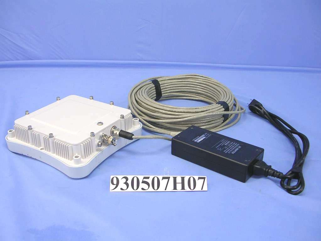
Click to zoom
Application Details
- Equipment Class
- DTS - Digital Transmission System
- Date of Grant
- Dec 27, 2005
- Application Purpose
- Original Equipment
- Date of Application
- Dec 27, 2005
- Equipment Note
- Dual mode 2.4GHz / 5GHz Access Point
- Frequency Range
- 5745.00000000 - 5825.00000000
- Company
- Juniper Networks, Inc.
- Country
- United States
Documents & Files
Document Text
Text extracted from the exhibit documents filed with the FCC. Open a document above to read the original.
Users Manual
Trapeze Networks, Inc. 5753 W. Las Positas Blvd. Pleasanton, CA 94588 Tel: +1 925-474-2200 Fax: +1 925-251-0642 Toll-Free: 877-FLY-TRPZ (877-359-8779)Part Number: 730-9502-0099, Revision A For the most current version of all documentation seewww.trapezenetworks.com Trapeze Networks™ Regulatory Information This document contains important safety information. Read all the safety warnings before you begin installation. Hardware Safety Symbols Trapeze Networks Mobility System™ products are labeled with one or more of the following safety symbols: Hardware Safety Symbols . . . . . . . . . . . . . . . . . . . . . . . . . . . . . . . . . . . . . . . . . . . . . . . . . . . . . . . . . . . . 1 Regulatory Compliance Information . . . . . . . . . . . . . . . . . . . . . . . . . . . . . . . . . . . . . . . . . . . . . . . . . . . 10 Declarations of Conformity . . . . . . . . . . . . . . . . . . . . . . . . . . . . . . . . . . . . . . . . . . . . . . . . . . . . . . . . . . 15 Warnings and Warning Conventions . . . . . . . . . . . . . . . . . . . . . . . . . . . . . . . . . . . . . . . . . . . . . . . . . . . 17 Warning! High voltage. Warnung! Hochspannung. Avertissement ! Haute tension. Attenzione! Alta tensione. ¡Advertencia! Alta tensión. Advertência! Alta tensão. Varning! Hög spänning. Advarsel! Højspænding. Advarsel! Høyspenning. Pas op! Hoogspanning. Viðvörun! Háspenna. Hardware Safety Symbols Trapeze Networks™ Regulatory Information 2 Attention! Refer to the manual. Vorsicht! Im Handbuch nachlesen. Attention! Consulter le manuel. Attenzione! Consultare il manuale. ¡Atención! Consulte el manual. Atenção! Consulte o manual. Obs! Se manualen. Bemærk! Se vejledningen. OBS! Slå opp i brukerhåndbok. Let op! Raadpleeg de handleiding. Takið eftir! Vísað til leiðarvísis. Προσοχή! Υψηλή τάση. 경고! 고압 제품. 警告! 高圧 警告! 高电压。 警告! 高電壓。 Осторожно! Высокое напряжение. !אזהרה .גבוה מתח !אזהרה Προσοχή! Συμβουλευτείτε το εγχειρίδιο χρήσης. 주의! 설명서를 참조하십시오. 注意! マニュアルを参照してください。 注意! 请参照手册。 注意! 請參照手冊。 Внимание! Обратитесь к инструкции. Trapeze Networks™ Regulatory Information 3 Hardware Safety Symbols Warning! Class 1 Laser. Warnung! Klasse-1-Laser. Avertissement ! Laser de Classe 1. Attenzione! Laser Classe 1. ¡Advertencia! Láser de clase 1. Advertência! Laser de classe 1. Varning! Klass 1 laser. Advarsel! Klasse 1-laser. Advarsel! Laser klasse 1. Pas op! Klasse 1-laser. Viðvörun! Leysir flokkur 1. Protective ground (earth) terminal. Erddungsschutzanschluss. Terminal de terre protecteur. Terminale di terra di protezione. Terminal de protección de toma de tierra. Terminal de protecção da toma de terra. Skyddande jordningsterminal. לב שים ! .במדריך עיין לב שים ! Προσοχή! Λέιζερ Κατηγορίας 1. 경고! 클래스 1 레이저 제품. 警告! クラス 1 レーザー 警告! 1级激光。 警告! 1級鐳射。 Осторожно! Лазер 1 класса. אזהרה! סיווג לייזר1. אזהרה! Hardware Safety Symbols Trapeze Networks™ Regulatory Information 4 Beskyttende jordklemme. Beskyttende jordtilkopling. Aardklem. Úttak fyrir verndandi jarðtengingu. Frame or chassis terminal. Rahmen- oder Untergestellanschluss. Terminal du cadre ou du châssis. Telaio o corpo del terminale. Terminal de bastidor o chasis. Terminal do bastidor ou chassis. Ram- eller chassisterminal. Rammeterminal. Tilkoplinger. Frame- of chassisklem. Tengistaðir. Προστατευτικό τερματικό γείωσης. 보호 접지 단자. 保護グランド(接地)ターミナル 保护性的接地终端 (接地)。 保護性的接地終端 (接地)。 Защитный контакт заземления. להארקה הגנה מחבר)אדמה.( Τερματικό Πλαισίου. 프레임 또는 섀시 단자. フレームまたはシャーシターミナル 结构或底盘终端。 結構或底盤終端。 Trapeze Networks™ Regulatory Information 5 Hardware Safety Symbols Direct current (DC). Gleichstrom (DC). Courant continu (DC/CC). Corrente continua (c.c.). Corriente continua (DC). Corrente contínua (DC). Likström (DC). Jævnstrøm (DC). Likestrøm (DC). Gelijkstroom. Jafnstraumur (DC). Alternating current (AC). Wechselstrom (AC). Courant alternatif (AC/CA). Corrente alternata (c.a.). Corriente alterna (AC). Corrente alterna (AC). Заземление на кросс или на массу. .מארז או מסגרת מחבר Συνεχές ρεύμα (DC). 직류 (DC). 直流(DC) 直流电 (DC)。 直流電 (DC)。 Постоянный ток (DC) .(DC) ישר זרם Hardware Safety Symbols Trapeze Networks™ Regulatory Information 6 Växelström (AC). Vekselstrøm (AC). Vekselstrøm (AC). Wisselstroom. Riðstraumur (AC). Complies with Underwriters Laboratories regulations in United States and Canada. Complies with Canadian Standard Association regulations in United States and Canada. The Competent Body reports issued by UL or CSA demonstrate the product safety compliance with the worldwide regulations. Erfüllt die Bestimmungen von Underwriters Laboratories in den Vereinigten Staaten und Kanada. Les rapports du Corps Compétent fournis par UL ou CSA confirment que la sécurité des produits est conforme aux règles internationales. I Rapporti dell’Organo Competente emessi da UL o CSA attestano la conformità del prodotto secondo le normative di sicurezza mondiali. Los informes de las entidades competentes emitidos por UL o CSA demuestran la que el producto cumple con los requisitos de seguridad de las regulaciones mundiales. Os relatórios emitidos pelo Corpo Competente de UL e CSA demonstram que a segurança dos produtos é cumprida de acordo com os regulamentos do mundo inteiro. Den kompetenta institutionens rapporter hanterade av UL eller CSA visar produktsäkerhetens tillmötesgående av världsomfattande regleringar. De myndighedsrapporter, der udstedes af UL (prøvningsudvalg for el-materiel) eller CSA (konføderationen, Sydstaterne), viser, at produktsikkerheden er i overensstemmelse med globale regulativer. Εναλλασσόμενο ρεύμα (AC). 교류 (AC). 交流 (AC) 交流电 (AC)。 交流電 (AC)。 Переменный ток (AC) .(AC) חילופין זרם Trapeze Networks™ Regulatory Information 7 Hardware Safety Symbols Rapporter fra kompetente instanser og er utgitt av UL eller CSA påviser at produktet oppfyller internasjonale retningslinjer om sikkerhet. Uit de rapporten van de Bevoegde Instantie uitgegeven door UL of CSA blijkt dat het product op het gebied van veiligheid voldoet aan de universele voorschriften. Skýrslur hæfra aðila, …
Text truncated - open the document above for the full version.
Users Manual
Trapeze Networks, Inc. 5753 W. Las Positas Blvd. Pleasanton, CA 94588 Tel: +1 925-474-2200 Fax: +1 925-251-0642 Toll-Free: 877-FLY-TRPZ (877-359-8779)Part Number: 730-9502-0066 Installing a Trapeze Networks™ Model MP-620 Mobility Point™ Access Point This document provides basic indoor hardware installation instructions for MP access point model MP-620. The MP-620 is suitable for installation outdoors. Mount the MP-620 . . . . . . . . . . . . . . . . . . . . . . . . . . . . . . . . . . . . . . . . . . . . . . . . . . . . . . . . . . . . . . . . . 5 Connect External Antenna(s) . . . . . . . . . . . . . . . . . . . . . . . . . . . . . . . . . . . . . . . . . . . . . . . . . . . . . . . . . 6 Connect Cables to the MP-620 . . . . . . . . . . . . . . . . . . . . . . . . . . . . . . . . . . . . . . . . . . . . . . . . . . . . . . . . 7 Connect the Power Injector . . . . . . . . . . . . . . . . . . . . . . . . . . . . . . . . . . . . . . . . . . . . . . . . . . . . . . . . . . . 8 Configure the MP-620 . . . . . . . . . . . . . . . . . . . . . . . . . . . . . . . . . . . . . . . . . . . . . . . . . . . . . . . . . . . . . . . 9 Installing a Trapeze Networks™ Model MP-620 Mobility Point™ Access Point 2 Qualified Service Personnel Warning Warning! Installation must be performed by qualified service personnel only. Read and follow all warning notices and instructions marked on the product or included in the documentation. Before installing the product, read the rest of this document. Waarschuwing! De installatie mag alleen worden uitgevoerd door bevoegd onderhoudspersoneel. Het is essentieel dat u kennis neemt van alle waarschuwingen en instructies aangebracht op het product zelf en/of opgenomen in de documentatie. Voordat u het product installeert, dient u dit document in zijn geheel te hebben gelezen. Warnung! Die Installation darf nur von qualifiziertem Servicepersonal vorgenommen werden. Lesen und befolgen Sie alle Warnhinweise und -anleitungen auf dem Produkt bzw. in der Dokumentation. Lesen Sie vor Installation des Produkts den restlichen Teil dieses Dokuments. Avertissement ! L’installation ne peut être effectuée que par un personnel qualifié. Lisez et suivez tous les messages d’avertissement et les instructions inscrits sur le produit ou inclus dans la documentation. Avant d’installer le produit, lisez le reste de ce document. Attenzione! L’installazione deve essere effettuata unicamente da personale qualificato. Leggere e rispettare tutte le segnalazioni di attenzione e le istruzioni indicate sul prodotto o incluse nella documentazione. Prima d’installare il prodotto, leggere tutto il documento. ¡Advertencia! La instalación debe realizarse exclusivamente por parte de personal de servicio cualificado. Lea y siga todas las notas de advertencia e instrucciones en el producto o la documentación. Antes de instalar el producto deberá leer la parte restante del presente documento. Advertência! A instalação dever ser realizada exclusivamente por pessoal de serviço qualificado. Leia e siga todas as notas de advertência e instrucões no produto ou na documentação. Antes de instalar o produto deverá ler a parte restante do presente documento. Varning! Installation får endast utföras av kvalificerad servicepersonal. Läs och följ alla varningsmeddelanden och instruktioner markerade på produkten eller inkluderade i dokumenteringen. Innan produkten installeras skall resten av dessa dokument läsas. Advarsel! Installation må kun gennemføres af faglært servicepersonale. Læs, og følg alle de advarselsmeddelelser og anvisninger, der er anført på produktet eller i dokumentationen. Læs resten af dette dokument før installation af produktet. Advarsel! Installasjon skal kun utføres av kvalifisert service personell. Les og følg alle varsels meldinger og instrukssjons merkinger på produktet og i veiledningen. Les resten av denne veiledningen før produktet installeres. Installing a Trapeze Networks™ Model MP-620 Mobility Point™ Access Point 3 Varoitus! Installatie dient uitsluitend plaats te vinden door bevoegde monteurs. Lees alle waarschuwingen en instructies die op het product zijn aangegeven of in de documentatie zijn opgenomen, en volg deze op. Lees voordat u het product installeert eerst de rest van dit document. Viðvörun! Aðeins hæfir þjónustufulltrúar mega sinna uppsetningu tækjanna. Lesið og fylgið öllum viðvörunum og leiðbeiningum í þessum gögnum. Lesið restina af þessum gögnum fyrir uppsetningu. Προσοχή! Η εγκατάσταση πρέπει να εκτελείται μόνο από εγκεκριμένο προσωπικό συντήρησης. ∆ιαβάστε και ακολουθείστε όλες τις προειδοποιήσεις και οδηγίες που αναγράφονται στο προϊόν ή που περιλαμβάνονται στην τεκμηρίωση. Πριν προβείτε στην εγκατάσταση του προϊόντος, διαβάστε το υπόλοιπο έγγραφο. 경고! 공인 서비스 기사만 설치 작업을 수행할 수 있습니다. 제품에 표시되어 있거나 설명서에 포함된 모든 경고 문구 및 지침을 읽어 보시고 준수하십시오. 제품을 설치하기 전에 본 설명서를 전체적으로 읽어 보시기 바랍니다. Warning! 設置は、資格を持ったサービス要員のみが行えます。 製品に付いているあるいはドキュメントに含まれている全ての警告注意を 読み、それに従ってください。 製品を設置する前に、本ドキュメントの残りをお読みください。 警告!安装工作只能由合格服务人员进行。 请阅读且遵照所有在产品上或者在文件内标记的警告通知、说明。 在安装产品之前,请阅读这份文件的剩余部分。 Внимание! Монтаж должен производить только квалифицированный обслуживающий персонал. Прочтите и выполняйте все предупредительные примечания и инструкции, нанесенные на изделие или включенные в документацию. Перед монтажом изделия прочтите данный документ до конца. Installing a Trapeze Networks™ Model MP-620 Mobility Point™ Access Point 4 For more information about MP installation as well as safety and installation requirements, see the following: zTrapeze MP-620 Installation Guide zTrapeze Regulatory Information .הנקתהה עצבתת לע ידי יאנכט ךמסומ דבלב ! הרהזא ארק לעפו םאתהב לכל תורהזאה תוארוההו תונמוסמה .לע רצומה וא תועיפומ דועיתב .ארק ךמסמ הז ואולמב, ינפל תנקתה רצומה Installing a Trapeze Networks™ Model MP-620 Mobility Point™ Access Point 5 Mount the MP-620 Mount the MP-620 You can mount the MP-620 on a pole or on a wall using the supplied hardware. Using the Pole-Mounting Bracket Perform the following steps to mount the unit …
Text truncated - open the document above for the full version.
Users Manual
Trapeze Networks, Inc. 5753 W. Las Positas Blvd. Pleasanton, CA 94588 Tel: +1 925-474-2200 Fax: +1 925-251-0642 Toll-Free: 877-FLY-TRPZ (877-359-8779)Part Number: 735-9502-0023, Revision A For the most current version of this document seewww.trapezenetworks.com Release Notes for Trapeze Networks™ Mobility Point™ Access Points Distributed MPs and Link Autonegotiation Description The Ethernet interfaces on an MP are configured to autonegotiate the link speed (10 Mbps or 100 Mbps) and mode (half duplex or full duplex). The setting cannot be changed. A common setting on third-party switches is 100 Mbps, with full duplex. If you connect a Distributed MP to a port that is set for 100 Mbps with full duplex, the MP operates at 100 Mbps with half duplex. This results in an unusable link. Workaround Configure the port on the other device to autonegotiate. Distributed MPs and STP Description A Distributed MP is a leaf device. You do not need to enable STP on the port that is directly connected to the MP. If Spanning Tree Protocol (STP) is enabled on the port that is directly connected to a Distributed MP, you might need to change the STP configuration on the port, to allow the MP to boot. Distributed MPs and Link Autonegotiation . . . . . . . . . . . . . . . . . . . . . . . . . . . . . . . . . . . . . . . . . . . . . . 1 Distributed MPs and STP . . . . . . . . . . . . . . . . . . . . . . . . . . . . . . . . . . . . . . . . . . . . . . . . . . . . . . . . . . . . 1 MP-620 BNC Connector Is Not Used . . . . . . . . . . . . . . . . . . . . . . . . . . . . . . . . . . . . . . . . . . . . . . . . . . . 2 Power Over Ethernet Support . . . . . . . . . . . . . . . . . . . . . . . . . . . . . . . . . . . . . . . . . . . . . . . . . . . . . . . . . 3 Note. STP on a port directly connected to a Distributed MP can prevent the MP from booting. MP-620 BNC Connector Is Not Used Release Notes for Trapeze Networks™ Mobility Point™ Access Points 2 As part of the boot process, an MP disables and reenables the link on the port over which the MP is attempting to boot. If STP is enabled on the device that is directly connected to the port, the link state change can cause the port on the other device to leave the forwarding state and stop forwarding traffic. The port remains unable to forward traffic for the duration of the STP forwarding delay. An MP waits 30 seconds to receive a reply to its DHCP Discover message, then tries to boot using the other MP port. If the boot attempt fails on the other port also, the MP then reattempts to boot on the first port. The process continues until a boot attempt is successful. If STP prevents the other device’s port from forwarding traffic during each boot attempt, the MP repeatedly disables and reenables the link, causing STP to repeatedly stop the other device’s port from forwarding traffic. As a result, the boot attempt is never successful. Workaround To allow an MP to boot over a link that has STP enabled, do one of the following on the other device: zDisable STP on the other device’s port. zEnable the port fast convergence feature, if supported, on the other device’s port. (On some vendors’ devices, this feature is called PortFast.) zIf the other device is running Rapid Spanning Tree or Multiple Spanning Tree, set the port into edge port mode. MP-620 BNC Connector Is Not Used The MP-620 has a BNC connector located between the Ethernet port and the grounding point screw. (See Figure 1.) This port is not used in MSS Version 4.1. Figure 1. MP Access Point Model MP-620—Bottom View Ethernet Port RSSI Connector with Protective Cap Grounding Point Screw Release Notes for Trapeze Networks™ Mobility Point™ Access Points 3 Power Over Ethernet Support Power Over Ethernet Support Trapeze Networks recommends that you budget for a minimum of 9 Watts of power draw per MP, for model MP-372. For an MP-620, budget for a maximum power draw of 30 Watts. For all other models, budget for a maximum power draw of 8 Watts per MP. Table 1 lists the Power over Ethernet (PoE) sources from which MPs can accept power. Table 2 lists the MP models that support 802.3af and the 802.3af classes of these models. Table 1. PoE Sources Supported By Trapeze MPs PoE SourceWire Pairs Used by PoE MP-3xx MP-52 MP-620 MP-2xx MP-1xx MX-20, MX-8, or MXR-2Pairs unused for trafficSupportedNot SupportedSupported PowerDsine 802.3afPairs unused for trafficSupportedNot SupportedSupported MP-620 PoE injectorPairs unused for trafficNot Supported Supported 1 1. Use only the PoE injector that is shipped with the MP-620. Not Supported Cisco product with AF in product ID Pairs also used for traffic (802.11af-compliant) SupportedNot SupportedNot Supported Cisco PoE blade with PWR in product ID 2 2. If your Cisco product has V in the product ID, contact your vendor to determine whether the product is AF-compliant. Pairs also used for traffic (proprietary) Not SupportedNot SupportedNot Supported Cisco PoE injector (AIR-PWR-xxx) Pairs also used for traffic (proprietary) Not SupportedNot SupportedNot Supported Table 2. MP Models that Support 802.3af MP ModelMP-372MP-620 MP-352 MP-341 MP-2xx MP-1xx MP-52 802.3af Supported?Ye sN oYe sN oYe s 802.3af Class3Not Applicable0Not Applicable0 © 2005 Trapeze Networks, Inc. All rights reserved. Trapeze Networks, the Trapeze Networks logo, the Trapeze Networks flyer icon, Mobility System, Mobility Exchange, MX, Mobility Point, MP, Mobility System Software, MSS, RingMaster, AAA Integration and RADIUS Scaling, ActiveScan, AIRS, Bonded Auth, FastRoaming, Granular Transmit Power Setting, GTPS, GuestPass, Layer 3 Path Preservation, Location Policy Rule, LPR, Mobility Domain, Mobility Profile, Passport-Free Roaming, SentryScan, Time-of-Day Access, TDA, TAPA, Trapeze Access Point Access Protocol, Virtual Private Group, VPG, Virtual Service Set, Virtual Site Survey and WebAAA are trademarks of Trapeze Networks, Inc. Trapeze Networks SafetyNet is a service mark of Trapeze Networks, Inc. All other products and ser…
Text truncated - open the document above for the full version.
Cover Letter(s)
Professional Installation Attestation Date: December 23 rd , 2005 To Whom It May Concern: Please be advised that due to the unique Market and function targeted by this product, this product will need special trained professional in configuring and installing the product. We hereby declare that the product will be distributed through controlled distribution channel which has special trained professional to install this product and will not be sold directly to the general public through retail store. Thank you for your attention. Yours sincerely, __________________________________________ Marko Radojicic Compliance Engineering Manager Trapeze Networks, Inc. 5753 West Las Positas Blvd Phone: 925-474-2217 Fax: 925-251-0642 E-mail: www.trapezenetworks.com
External Photos
Page 1 CONSTRUCTION PHOTOS OF EUT EUT With Adapter Page 2 EUT With Antenna Model No.: ACC04-090380 Page 3 EUT With Antenna Model No.: ACC04-05427A
ID Label/Location Info
FCC LABEL LOCATION The label will be permanently affixed at a conspicuous location on the device. LABEL (Fig. 1) FCC ID: QZE300
Internal Photos
Page 4 Page 5 Page 6 Page 7 Page 8 Page 9 Page 10 Page 11 Page 12 Page 13
Internal Photos
Page 14 Antenna Model No.: ACC04-090380 Page 15 Page 16 Antenna Model No.: ACC04-05427A Page 17 Adapter Page 18 Page 19 Page 20 Page 21 Page 22 Page 23
Operational Description
FCC ID: QZE300 Report No. RF930507H07P Technical Description This device is a Dual mode 2.4GHz / 5GHz Access Point operates in both the 5GHz and 2.4GHz bands with DSSS and OFDM technique. The transmitter rate could be 1/2/5.5/6/9/11/12/18/24/36/48/54Mbps, and the maximum data rate could be up to 108Mbps in turbo mode. The transmitter of the EUT is powered by POE. The antenna are Omnidirectional (Dipole Antenna) with N-type connector. Under normal use condition, the user has to keep at least 20 cm separation distance between radiator and the body of the user. For more detailed instruction, please refer to the user’s manual. FCC 15.407(c) states : The device shall automatically discontinue transmission in case of either absence of information to transmit or operational failure. These provisions are not intended to preclude the transmission of control or signaling information or the use of repetitive codes used by certain digital technologies to complete frame or burst intervals. Applicants shall include in their application for equipment authorization a description of hoe this requirement is met. Data transmission is always initiated by software, which is then pass down through the MAC, through the digital and analog baseband, and finally to the RF chip. Several special packets (ACKs, CTS, PSPoll, etc...) are initiated by the MAC. There are the only ways the digital baseband portion will turn on the RF transmitter, which it then turns off at the end of the packet. Therefore, the transmitter will be on only while one of the aforementioned packets are being transmitted.
RF Exposure Info
FCC ID: QZE300 Report No.: SA930507H07P1Issued: Dec. 20, 2005 Reference No.: 941123H01 RF EXPOSURE REPORT REPORT NO.: SA930507H07P MODEL NO.: MP-620 ACCORDING: FCC Guidelines for Human Exposure IEEE C95.1 APPLICANT: Trapeze Networks, Inc. ADDRESS: 5753 W. Las Positas Blvd., Pleasanton, CA 94588 ISSUED BY: Advance Data Technology Corporation LAB LOCATION: No. 81-1, Lu Liao Keng, 9 Ling, Wu Lung Tsuen, Chiung Lin Hsiang, Hsin Chu Hsien, Taiwan, R.O.C. FCC ID: QZE300 Report No.: SA930507H07P2Issued: Dec. 20, 2005 Reference No.: 941123H01 RF Exposure Measurement 1. Introduction In this document, we try to prove the safety of radiation harmfulness to the human body for our product. The limit for Maximum Permissible Exposure (MPE) specified in FCC 1.1310 is followed. The Gain of the antenna used in this product is measured in a Fully Anechoic Chamber (FAC) calibrated for antenna measurement in ADT, and also the maximum total power input to the antenna is measured. Through the Friis transmission formula and the maximum gain of the antenna, we can calculate the distance, away from the product, where the limit of MPE is reached. Although the Friis transmission formula is a far field assumption, the calculated result of that is an over-prediction for near field power density. We will take that as the worst case to specify the safety range. 2. RF Exposure Limit According to FCC 1.1310: The criteria listed in the following table shall be used to evaluate the environmental impact of human exposure to radio-frequency (RF) radiation as specified in 1.1307(b) LIMITS FOR MAXIMUM PERMISSIBLE EXPOSURE (MPE) Frequency Range (MHz) Electric Field Strength (V/m) Magnetic Field Strength (A/m) Power Density (mW/cm 2 ) Average Time (minutes) (A)Limits For Occupational / Control Exposures 300-1500......F/3006 1500-100,000......56 (B)Limits For General Population / Uncontrolled Exposure 300-1500......F/15006 1500-100,000......1.030 F = Frequency in MHz FCC ID: QZE300 Report No.: SA930507H07P3Issued: Dec. 20, 2005 Reference No.: 941123H01 3. Friis Formula Friis transmission formula : Pd = (Pout*G) / (4*pi*r 2 ) where Pd = power density in mW/cm 2 Pout = output power to antenna in mW G = gain of antenna in linear scale Pi = 3.1416 R = distance between observation point and center of the radiator in cm Pd is the limit of MPE, 1 mW/cm 2 . If we know the maximum Gain of the antenna and the total power input to the antenna, through the calculation, we will know the MPE value at distance 20cm. Ref. : David K. Cheng, Field and Wave Electromagnetics, Second Edition, Page 640, Eq. (11-133). 4 EUT Operating condition The software provided by Manufacturer enabled the EUT to transmit and receive data at lowest, middle and highest channel individually. 5. Classification This is a stand alone radio device. So under normal use condition, it is easy to be re- located in the place where at least 20 cm far away from the body of the user. Warning statement to the user for keeping at least 20cm or more separation distance with the antenna should be included in users manual. So, this device is classified as Mobile Device. FCC ID: QZE300 Report No.: SA930507H07P4Issued: Dec. 20, 2005 Reference No.: 941123H01 6 Test Results 6.1 Antenna Gain For 2.4GHz The maximum Gain measured in Fully Anechoic Chamber is 8.0dBi or 6.31(numeric) For 5GHz The maximum Gain measured in Fully Anechoic Chamber is 8.0dBi or 6.31(numeric) 6.2 Output Power Into Antenna & RF Exposure value at distance 20cm: For 2.4GHz 802.11b: Channel Channel Frequency (MHz) Output Power to Antenna (mW) Power Density (mW/cm 2 ) Limit of Power Density (mW/cm 2 ) 1241231.6230.0401.0 62437125.8930.1581.0 11246256.2340.0711.0 802.11g: Channel Channel Frequency (MHz) Output Power to Antenna (mW) Power Density (mW/cm 2 ) Limit of Power Density (mW/cm 2 ) 1241235.4810.0451.0 62437131.8260.1651.0 11246258.8840.0741.0 For 5GHz Channel Channel Frequency (MHz) Output Power to Antenna (mW) Power Density (mW/cm 2 ) Limit of Power Density (mW/cm 2 ) 15745186.6380.2342767171.0 35785164.0590.2073619791.0 55825142.5610.2073619791.0 Turbo 15760165.1960.2073619791.0 Turbo 25800146.8930.1843865041.0
Test Report
FCC ID: QZE300 Report No.: RF930507H07P1Report Format Version 2.0.4 Reference No.: 941123H01 FCC TEST REPORT (15.247) REPORT NO.: RF930507H07P MODEL NO.: MP-620 RECEIVED: Nov. 23, 2005 TESTED: Dec. 04 to 16, 2005 ISSUED: Dec. 20, 2005 APPLICANT: Trapeze Networks, Inc. ADDRESS: 5753 W. Las Positas Blvd., Pleasanton, CA 94588 ISSUED BY: Advance Data Technology Corporation TEST LOCATION: No. 81-1, Lu Liao Keng, 9 Ling, Wu Lung Tsuen, Chiung Lin Hsiang, Hsin Chu Hsien, Taiwan, R.O.C. This test report consists of 110 pages in total. It may be duplicated completely for legal use with the approval of the applicant. It should not be reproduced except in full, without the written approval of our laboratory. The client should not use it to claim product endorsement by CNLA, A2LA or any government agencies. The test results in the report only apply to the tested sample. The test results in this report are traceable to the national or international standards. 0536No. 2177-01 ILAC MRA FCC ID: QZE300 Report No.: RF930507H07P2Report Format Version 2.0.4 Reference No.: 941123H01 Table of Contents 1.CERTIFICATION..............................................................................................6 2.SUMMARY OF TEST RESULTS......................................................................7 3.GENERAL INFORMATION...............................................................................9 3.1GENERAL DESCRIPTION OF EUT.................................................................9 3.2DESCRIPTION OF TEST MODES.................................................................11 3.2.1TEST MODE APPLICABILITY AND TESTED CHANNEL DETAIL:................12 3.3GENERAL DESCRIPTION OF APPLIED STANDARDS................................14 3.4DESCRIPTION OF SUPPORT UNITS...........................................................15 3.5CONFIGURATION OF SYSTEM UNDER TEST............................................16 4.TEST TYPES AND RESULTS (802.11b & g, 2400 ~ 2483.5MHz Band)........18 4.1CONDUCTED EMISSION MEASUREMENT.................................................18 4.1.1LIMITS OF CONDUCTED EMISSION MEASUREMENT...............................18 4.1.2TEST INSTRUMENTS...................................................................................18 4.1.3TEST PROCEDURES....................................................................................19 4.1.4DEVIATION FROM TEST STANDARD..........................................................19 4.1.5TEST SETUP.................................................................................................20 4.1.6EUT OPERATING CONDITIONS...................................................................20 4.1.7TEST RESULTS.............................................................................................21 4.2RADIATED EMISSION MEASUREMENT......................................................23 4.2.1LIMITS OF RADIATED EMISSION MEASUREMENT....................................23 4.2.2TEST INSTRUMENTS...................................................................................24 4.2.3TEST PROCEDURES....................................................................................25 4.2.4DEVIATION FROM TEST STANDARD..........................................................25 4.2.5TEST SETUP.................................................................................................26 4.2.6EUT OPERATING CONDITIONS...................................................................26 4.2.7TEST RESULTS.............................................................................................27 4.36dB BANDWIDTH MEASUREMENT.............................................................34 4.3.1LIMITS OF 6DB BANDWIDTH MEASUREMENT..........................................34 4.3.2TEST INSTRUMENTS...................................................................................34 FCC ID: QZE300 Report No.: RF930507H07P3Report Format Version 2.0.4 Reference No.: 941123H01 4.3.3TEST PROCEDURE......................................................................................35 4.3.4DEVIATION FROM TEST STANDARD..........................................................35 4.3.5TEST SETUP.................................................................................................35 4.3.6EUT OPERATING CONDITIONS...................................................................35 4.3.7TEST RESULTS.............................................................................................36 4.4MAXIMUM PEAK OUTPUT POWER.............................................................42 4.4.1LIMITS OF MAXIMUM PEAK OUTPUT POWER MEASUREMENT..............42 4.4.2INSTRUMENTS.............................................................................................42 4.4.3TEST PROCEDURES....................................................................................43 4.4.4DEVIATION FROM TEST STANDARD..........................................................43 4…
Text truncated - open the document above for the full version.
Contact Information
Applicant
Mark Gandler(Sr. Manager Compliance Engineering)
Technical Contact
Advance Data Technology Corporation (Hsin Chu)Eric Lin
[email protected]886-3-593-5343
81-1 Luliaoken, 9th Lin, Wulung Tsuen Chiunglin · Hsinchu · Taiwan
Non-Technical Contact
Advance Data Technology CorporationEric Lin
[email protected]886-3-593-5343
Test Firm
Bureau Veritas CPS (H.K.) Ltd. Taoyuan BranchRichard Chen
Technical Specifications
| # | Rule Parts | Frequency Range | Power Output |
|---|---|---|---|
| 2 | 15C | 5.75 GHz - 5.83 GHz | 187.00 mW |
Other Applications from Juniper Networks, Inc.
QZEWLA532E
Oct 31, 2012WLA532E Wireless LAN Access Point
Equipment Class
NII - Unlicensed National Information Infrastructure TX
QZEWLA322
Jun 10, 2012WLA322 Wireless LAN Access Point
Equipment Class
NII - Unlicensed National Information Infrastructure TX
QZEWLA321
Apr 01, 2012WLA321 Wireless LAN Access Point
Equipment Class
NII - Unlicensed National Information Infrastructure TX
QZEWLA532
Nov 16, 2011WLA532 Wirelesss LAN Access Point
Equipment Class
DTS - Digital Transmission System
QZE520
Jul 14, 2010Enterprise Access Point
Equipment Class
DTS - Digital Transmission System