QZHSCILDA305Magnetic Switch Transmitter
Styling city industries ltd.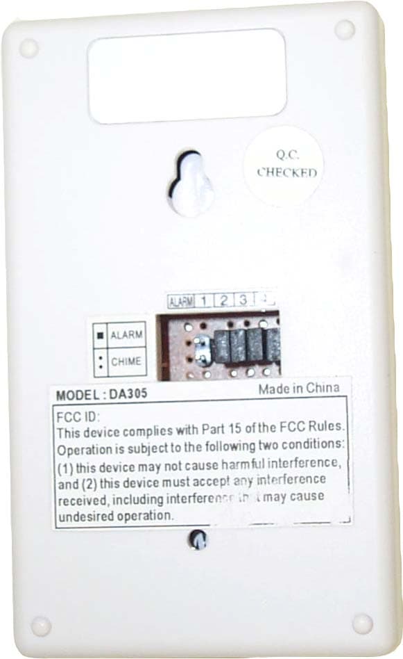
Click to zoom
Application Details
- Equipment Class
- DSC - Part 15 Security/Remote Control Transmitter
- Date of Grant
- Apr 13, 2003
- Application Purpose
- Original Equipment
- Date of Application
- Apr 13, 2003
- Equipment Note
- Magnetic Switch Transmitter
- Frequency Range
- 434.00000000 - 434.00000000
- Company
- Styling city industries ltd.
- Country
- Hong Kong
Documents & Files
Document Text
Text extracted from the exhibit documents filed with the FCC. Open a document above to read the original.
Users Manual
DA-305 Magnetic Switch Transmitter The DA-305 Magnetic Switch Transmitter is designed to work with the Door Chime/Alarm, and no wiring is required. The Magnetic Switch Transmitter detects any entry from window or door. Battery Installation 1. Remove the locking screw and slide open the battery compartment cover at the front of Magnetic Switch Transmitter 2. Insert 1x9 volt alkaline battery, and ensuring the battery polarity match the internal marking. 3. Replace the battery compartment cover and screw, then it is ready to use. Operation When the door or window is opened, it activated the sensor. The LED will light up in Green as indication, it sends a wireless signal to the Door Chime/Alarm that activates either the chime or the alarm. The operating range is upto 30metres (100ft approx.), it can work with the Door Chime/ Alarm virtually anywhere in the home, workshop, office or garden. Installation 1. Take one of the mounting screws and screw it into position leaving it protruding by 5mm. 2. Slot the Magnetic Switch onto the screw, and screw the second screw through the hole inside battery compartment to the wall to secure the unit into position, then replace battery compartment cover. 3. Proper positioning of the Magnetic Switch Transmitter is important. Ensure that the Magnetic Switch Transmitter and Magnet are parallel and the arrows are pointing directly at one another. Separation between the pieces must not exceed 12mm (1/2 inch.) 4. Magnet can be mounted on either side of Magnetic Switch Transmitter. 5. Test to ensure the Magnetic Switch Transmitter is located within the operation range before final installation. Channel Set Up The Magnetic Switch Transmitter is pre-set at certain channel. During installation, ensure that it is set to the same code as the Door Chime/Alarm. 1. At the back of Magnetic Switch Transmitter, there is 4 black links in a row, in position 1, 2, 3 & 4, which can be altered to achieve total sixteen (16) possible channels. 2. Add and remove one or more the black link(s), in any combination ensuring it is set to the same code as Door Chime/Alarm unit. 3. Test to ensure correct operation before final installation. Door Chime and Home Alarm Function Magnetic Switch Transmitter can be selected to activate either Door Chime or Home Alarm function that built in the Door Chime/Alarm unit once movement is detected. Door Chime Function Magnetic Switch Transmitter is factory pre-set to activate Door Chime function, if it is the function that you want, then no change is required. When use the Door Chime function, there is total 8 different melodies can be selected as Chime sound. The melody selector is located inside the top right of battery compartment, simply press it to select the melody. The PIR Transmitter is pre-set to “Westminster” therefore, if no change is required, it should not be adjusted. Replace the battery compartment cover and screw, once melody is selected. 1) Long Westminster Chime (8-notes) 5) Banjo on my knee 2) Ding-Dong (2-times) 6) Twinkle-twinkle 3) Telephone Ring 7) It is a small world 4) Circus theme 8) Dog Barking Home Alarm Function It can work with the Home Security Alarm function that built in the Door Chime/Alarm and External Siren units. In order to activate the alarm function on the Door Chime/Alarm unit, you need to use the Remote Control unit to arm and disarm the Door Chime/Alarm Unit, follows instruction below. a) There is a black links marked A, which is located at the back of Magnetic Switch Transmitter. b) Add one black link onto it, it will switch “ON” alarm function on the Magnetic Switch Transmitter, at the same time Door Chime (Visitor Announcer) function will be switched “OFF”. Important note: If Door Chime/Alarm unit has not been armed by remote control (read follow instruction), alarm function will not be performed even though Magnetic Switch Transmitter is switched to alarm function. Arm & Disarm the Door Chime/Alarm unit Simply press the remote control unit once, the Door Chime/Alarm unit will beep once and the Green LED will illuminate for approximately 30 seconds to indicate the unit is armed. Thirty seconds after you have left the protected zone, the Green LED will extinguish and the unit will become fully armed. When each secured door/window is opened and detected by Magnetic Switch Transmitter, or any movement detected by PIR Sensor Transmitter, the LED light on these transmitters will light up for about 2 seconds, and the Door Chime/Alarm or External Siren unit will beep once to indicate that you have 8 seconds in which to disarm the unit. To disarm, simply press the remote control unit once, the Door Chime/Alarm unit will emit a double beep to indicate that it is now disarmed. If the Door Chime/Alarm unit is not disarmed within the 8 seconds, the unit will emit a loud alarm sound for 45 seconds to alert the occupants of the house to an intruder. To disarm the unit under these circumstances, simply press the remote control unit once, the Door Chime/Alarm unit will emit a double beep to indicate that it is now disarmed. Important 1. Do not mount the Magnetic Switch Transmitter onto any metal surfaces or UPVC doorframe, as this will reduce the operation range seriously. 2. Do not expose the Magnetic Switch Transmitter directly to rain or immerse in water. 3. Do not mount the unit close to fireplace or expose to high temperature. 4. Do not use rechargeable battery. 5. Do not leave exhausted batteries in either unit. If leaving the PIR Sensor Transmitter for long periods, remove the battery from compartment to prevent leakage. 6. Always use alkaline battery as it will give longer service and are less likely to leak. 7. The Magnetic Switch Transmitter is designed for indoor use only. 8. Please dispose of old, defective batteries in and environmental friendly manner in accordance with the relevant legislation. 9. Make sure that no naked flame sources, such as lighted candles, should be placed on the unit. 10. The unit shou…
Text truncated - open the document above for the full version.
Block Diagram
Block Diagram
External Photos
Front View Rear View Open View
ID Label/Location Info
FCC ID Label Location of Label on Back of the EUT FCC LABEL FCC ID: QZHSCILDA305 This device complies with Part 15 of the FCC Rules. Operation is subject to the following two conditions: (1) this device may not cause harmful interference. and (2) this device must accept any interference received, including interference that may cause undesired operation.
Internal Photos
Open View FCC ID: QZHSCILDA305 ——————————————————————————————————————————————— Advanced Compliance Lab 6 Randolph Way, Hillsborough, NJ 08844 Tel: (908) 927-9288 Fax: (908) 927-0728 2 Component Side FCC ID: QZHSCILDA305 ——————————————————————————————————————————————— Advanced Compliance Lab 6 Randolph Way, Hillsborough, NJ 08844 Tel: (908) 927-9288 Fax: (908) 927-0728 3 Foil Side
Operational Description
Model: DA305 OPERATIONAL CIRCUIT DESCRIPTION U1 is a micro controller, when activated K1, K2 (magnetic reed switch) through Q1 to generates a digital signal to Q2 (R.F. osc.) and modulated to a high frequency signal last for 2 seconds. U2 is a 3V regulator for U1 power supply. POWER SUPPLY AND GROUND One 9V battery is the only power supply for the transmitter. No external power is needed.
Schematics
System Schematics
Test Report
ELECTROMAGNETIC EMISSION COMPLIANCE REPORT of MAGNETIC SWITCH TRANSMITTER MODEL: DA305 FCC ID: QZHSCILDA305 March 28, 2003 This report concerns (check one): Original grant x Class II change Equipment type: TRANSMITTER Deferred grant requested per 47 CF 0.457(d)(1)(ii)? yes no x If yes, defer until: (date) Company agrees to notify the Commission by (date) of the intended date of announcement of the product so that the grant can be issued on that date. Transition Rules Request per 15.37? yes no x If no, assumed Part 15, Subpart B for unintentional radiators - the new 47 CFR [10-1-90 Edition] provision. Report prepared for: STYLING CITY INDUSTRIES LTD . Report prepared by: Advanced Compliance Lab Report number: 0048-030318-04 The test result in this report IS supported and covered by the NVLAP accreditation 6 Randolph Way Hillsborough, NJ 08844 Tel: (908) 927 9288 Fax: (908) 927 0728 Advanced Compliance Laboratory FCC ID: QZHSCILDA305 ——————————————————————————————————————————————— Advanced Compliance Lab 6 Randolph Way, Hillsborough, NJ 08844 Tel: (908) 927-9288 Fax: (908) 927-0728 2 Table of Contents Report Cover Page .........................................................................................................1 Table of Contents ...........................................................................................................2 Figures.............................................................................................................................3 1. GENERAL INFORMATION ...................................................................................4 1.1 Verification of Compliance .........................................................................4 1.2 Equipment Modifications............................................................................5 1.3 Product Information....................................................................................6 1.4 Test Methodology.........................................................................................6 1.5 Test Facility ..................................................................................................6 1.6 Test Equipment ............................................................................................6 1.7 Statement of the Document Use..................................................................7 2. PRODUCT LABELING............................................................................................8 3. SYSTEM TEST CONFIGURATION ......................................................................9 3.1 Justification ..................................................................................................9 3.2 Special Accessories.......................................................................................9 3.3 Configuration of Tested System .................................................................9 4. SYSTEM SCHEMATICS .........................................................................................12 5. RADIATED EMISSION DATA ...............................................................................13 5.1 Field Strength Calculation ..........................................................................13 5.2 Test Methods and Conditions .....................................................................13 5.3 Test Data .......................................................................................................14 5.4 Occupied Bandwidth ...................................................................................15 6. PHOTOS OF TESTED EUT ....................................................................................16 FCC ID: QZHSCILDA305 ——————————————————————————————————————————————— Advanced Compliance Lab 6 Randolph Way, Hillsborough, NJ 08844 Tel: (908) 927-9288 Fax: (908) 927-0728 3 Figures Figure 2.1 FCC ID Label...............................................................................................8 Figure 2.2 Location of Label on Back of the EUT ......................................................8 Figure 3.1 Radiated Test Setup, Position 1..................................................................10 Figure 3.2 Radiated Test Setup, Position 2..................................................................10 Figure 3.3 Radiated Test Setup, Position 3..................................................................11 Figure 4.1 EUT Schematics ...........................................................................................12 Figure 5.1 Occupied Bandwidth ...................................................................................15 Figure 6.1 Front View....................................................................................................17 Figure 6.2 Rear View .....................................................................................................18 Figure 6.3 Inside View, Cover Opened ........................................................................19 Figure 6.4 Component Side ...........................................................................................20 Figure 6.5 Foil Side ........................................................................................................21 FCC ID: QZHSCILDA305 ——————————————————————————————————————————————— Advanced Compliance Lab 6 Randolph Way, Hillsborough, NJ 08844 Tel: (908) 927-9288 Fax: (908) 927-0728 4 1. GENERAL INFORMATION 1.1 Verification of Compliance EUT: MAGNETIC SWITCH TRANSMITTER Model: DA305 Applicant: STYLING CITY INDUSTRIES LTD. Test Type: FCC Part 15C CERTIFICATION Result: PASS Tested by: ADVANCED COMPLIANCE LAB Test Date: March 28, 2003 Report Number: 0048-030318-04 The above equipment was tested by Advanced Compliance Lab. Compliance Laboratory for compliance with the requirement set forth in the FCC rules and regulations Part 15, subpart C. This said equipment in the configuration described in the report, shows the maximum emi…
Text truncated - open the document above for the full version.
Test Report
Pulse Train Plot
Test Setup Photos
Radiated Test Setup, Position 1-X Radiated Test Setup, Position 2 -Y Radiated Test Setup, Position 3-Z
Contact Information
Applicant
K.W. Lam(Admin.)
Test Firm
Advanced Compliance LaboratoryWei Li
Technical Specifications
| # | Rule Parts | Frequency Range | Power Output |
|---|---|---|---|
| 1 | 15.231 | 434 MHz - 434 MHz | - |
Other Applications from Styling city industries ltd.
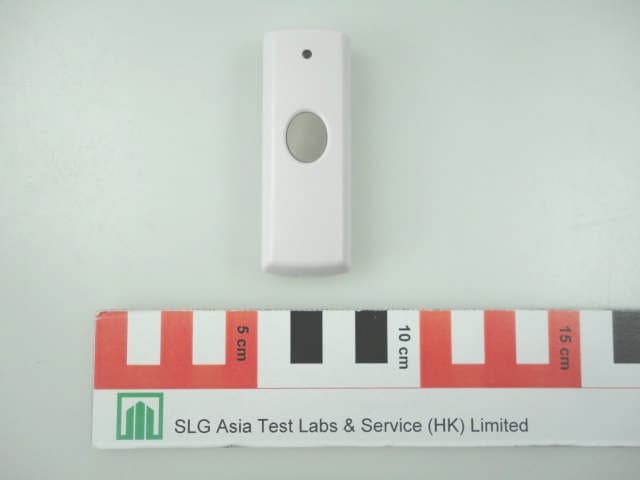
QZHSC335T
Aug 24, 2012Wireless Doorbell Transmitter
Equipment Class
DSC - Part 15 Security/Remote Control Transmitter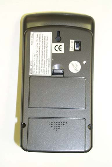
QZHSCILSC352
Nov 17, 2004Wireless Doorbell Receiver w/ Digital Clock
Equipment Class
CRR - Superregenerative Receiver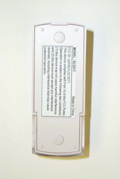
QZHSCILSC321T
Nov 17, 2004Wireless Doorbell Transmitter
Equipment Class
DSC - Part 15 Security/Remote Control Transmitter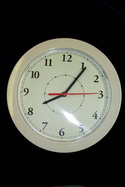
QZHSCILCD101
Nov 17, 2004Wireless Doorbell Receiver w/ Analog Clock
Equipment Class
CRR - Superregenerative Receiver
QZHSCILDA302
Apr 13, 2003PIR Sensor Transmitter
Equipment Class
DSC - Part 15 Security/Remote Control Transmitter