R38YLWM0404Wireless Data Modem
Yulong Computer Telecommunication Scientific (Shenzhen) Co. LTD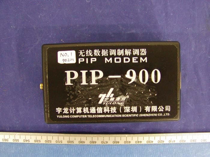
Click to zoom
Application Details
- Equipment Class
- TNB - Licensed Non-Broadcast Station Transmitter
- Date of Grant
- May 03, 2004
- Application Purpose
- Original Equipment
- Date of Application
- May 03, 2004
- Equipment Note
- Wireless Data Modem
- Frequency Range
- 896.00000000 - 901.00000000
- Country
- China
Documents & Files
Document Text
Text extracted from the exhibit documents filed with the FCC. Open a document above to read the original.
Users Manual
Modem setup manual 1. PC requirement: must have a Serial COM , Operation System can use Windows 98 or Windows 2000. 2. Connect PC and PIP900 modem RSCSTRRDTDCD TALK / DATA TALK AC ADAPTER COM POWER IN PI P9 0 0 AC I N 7V- 12VDC PC PI P900 CONNECT WITH PC diagram 1: Connect PC and PIP900 modem 3. Start modemsetup software There are two dialogs in the modemsetup software. The first dialog is SETUP (diagram 2 and diagram 3). This dialog used to setup COM parameter. After finished set COM parameter, push the Connect[C] button to connect the PIP900 modem. The second dialog is Te s t Tr a n s m i t (diagram 3). This dialog used to select Transmit Power, Modulate Data kinds and Transmit Duty. If you want to output Max Power, please select Power level 4(MAX). Operation Step: a. Connect PC and PIP900 use special cable. b. In SETUP dialog select the COM (COM1 or COM2 etc.) then push the Open[O] button to open COM port, If success to connect the PIP900 modem, you can change to the Te s t Transmi t dialog to test the modem transmit functions. c. In Test Transmit dialog, select Power Level 4(Max) in functions window. You may change Modulation kinds and Transmit Duty value then select Send button to send command to PIP900. (Note: items means in the Modulation kinds, only 1 means positive frequency deviation, only 0 means negative frequency deviation, center means center frequency, PN9 scramble means use PN9 modulation data, dynamic frequency use to test dynamic frequency deviation) d. The continuous transmission of a modulation carrier (PN9 modulation or dynamic frequency with fixed Data modulation) for longer periods when you set the Duty_off to 0. but you can’t change the parameters again in this mode, till you reset the pip900 modem(by power down). e. The item others may not use. diagram 2:SETUP menu 1 diagram 3 : SETUP menu 2 diagram 4:Test Transmit menu FCC Part 2 certification requires all integrated products to have routine environmental evaluation for radio-frequency (RF) exposure prior to equipment authorization or use in accordance with FCC rules 2.1091 and 2.1093 and FCC Guidelines for Human Exposure to Radio Frequency Electromagnetic Fields, OET Bulletin 65 and its Supplement C. For “mobile or fixed devices”, defined as transmitting devices designed to be generally used such that a separation distance of at least 20 cm is maintained between the body of the user and the transmitting radiated structure, Maximum Permissible Exposure (MPE) limits may be used with field strength or power density limit of 0.597 mW/cm2 (at 896 MHz). "To satisfy FCC RF exposure requirements a separation distance of 20 cm or more should be maintained between the antenna of this device and persons during device operation. To ensure compliance, operations at closer than this distance is not recommended." “Regulatory Notice of Compliance This equipment has been tested and found to comply within the limits for a Class B digital device, pursuant to Part 15 of the FCC Rules. These limits are designed to provide reasonable protection against harmful interference in a residential installation. This equipment generates, uses, and can radiate radio frequency energy and, if not installed and used in accordance with the instructions, may cause harmful interference to radio communications. However, there is no guarantee that interference will not occur in a particular installation. If this equipment does cause harmful interference to radio or television reception, which can be determined by turning the equipment off and on, the user is encouraged to try to correct the interference by one or more of the following measures: Reorient or relocate the receiving antenna. Increase the separation between the equipment and receiver. Connect the equipment into an outlet on a circuit different from that to which the receiver is connected. Consult the dealer or an experienced radio/TV technician for help.”
External Photos
YULONG COMPUTER TELECOMMUNICATION SCIENTIFIC (SHENZHEN) CO. LTD FCC ID: R38YLWM0404 APPENDIX C - EUT PHOTOGRAPHS Chassis - Front View Chassis – Rear View YULONG COMPUTER TELECOMMUNICATION SCIENTIFIC (SHENZHEN) CO. LTD FCC ID: R38YLWM0404 Cable View Antenna View YULONG COMPUTER TELECOMMUNICATION SCIENTIFIC (SHENZHEN) CO. LTD FCC ID: R38YLWM0404 Power Adapter View
ID Label/Location Info
APPENDIX A - FCC ID LABELING AND LOCATION Proposed FCC ID Labeling Proposed FCC ID Location Rear Side of EUT / Proposed Label Location The label is permenantly adhesive to the EUT. FCC ID: R38YLWM0404
Internal Photos
YULONG COMPUTER TELECOMMUNICATION SCIENTIFIC (SHENZHEN) CO. LTD FCC ID: R38YLWM0404 EUT – Board and Housing View EUT – Board Top View YULONG COMPUTER TELECOMMUNICATION SCIENTIFIC (SHENZHEN) CO. LTD FCC ID: R38YLWM0404 EUT – Board Bottom View EUT – Board Shield Cover Removed View
RF Exposure Info
§1.1307(b)(1) & §2.1091 - RF EXPOSURE According to §15.247(b)(5) and §1.1307(b)(1), systems operating under the provisions of this section shall be operated in a manner that ensures that the public is not exposed to radio frequency energy level in excess of the Commission’s guidelines. According to §1.1310 and §2.1091 RF exposure is calculated. Limits for General Population/Uncontrolled Exposure Frequency Range (MHz) Electric Field Strength (V/m) Magnetic Field Strength (A/m) Power Density (mW/cm 2 ) Averaging Time (minute) Limits for General Population/Uncontrolled Exposure 0.3-1.34 614 1.63 *(100) 30 1.34-30 824/f 2.19/f *(180/f 2 ) 30 30-300 27.5 0.073 0.2 30 300-1500 / / f/1500 30 1500-100,000 / / 1.0 30 f = frequency in MHz * = Plane-wave equivalent power density MPE Prediction Predication of MPE limit at a given distance Equation from page 18 of OET Bulletin 65, Edition 97-01 S = PG/4πR² Where: S = power density P = power input to antenna G = power gain of the antenna in the direction of interest relative to an isotropic radiator R = distance to the center of radiation of the antenna Maximum peak output power at antenna input terminal: 31.33 (dBm ) Maximum peak output power at antenna input terminal: 1358 (mW) Prediction distance: 20 (cm) Predication frequency: 900 (MHz) Antenna Gain (typical): 3 (dBi) antenna gain: 2.0 (numeric) Power density at predication frequency at 20 cm: 0.54(mW/cm 2 ) MPE limit for uncontrolled exposure at prediction frequency: 0.6 (mW/cm 2 ) Test Result The EUT is a mobile device. The power density level at 20 cm is 0.54 mW/cm², which is below the uncontrolled exposure limit of 0.6mW/cm² at 900 MHz.
Test Report
Note: This test report is specially limited to the above client company and product model. It may not be duplicated without prior written consent of Bay Area Compliance Laboratory Corporation. This report must not be used by the client to claim product endorsement by NVLAP or any agency of the U.S. Government. FCC PART 90 EMI MEASUREMENT AND TEST REPORT For YULONG COMPUTER TELECOMMUNICATION SCIENTIFIC (SHENZHEN) CO. LTD 8/F, B TOWER, HIGH TECH. PLAZA, TIANAN CRYBERPARK, SHENZHEN, CHINA FCC ID: R38YLWM0404 This Report Concerns: Original Report Equipment Type: Wireless Data Modem Test Engineer: Ming Jin Report Number: R0404063 Report Date: 2004-04-26 Reviewed By: Ling Zhang Prepared By: Bay Area Compliance Laboratory Corporation 230 Commercial Street Sunnyvale, CA 94085 Tel: (408) 732-9162 Fax: (408) 732 9164 YULONG COMPUTER TELECOMMUNICATION SCIENTIFIC (SHENZHEN) CO. LTD FCC ID: R38YLWM0404 Report # R0404063Rpt FCC Part 90 Test Report Page 2 of 18 TABLE OF CONTENTS GENERAL INFORMATION.......................................................................................................................................3 PRODUCT DESCRIPTION FOR EQUIPMENT UNDER TEST (EUT) ....................................................................................3 OBJECTIVE...................................................................................................................................................................3 RELATED GRANT/SUBMISSION.....................................................................................................................................3 TEST METHODOLOGY..................................................................................................................................................3 TEST FACILITY.............................................................................................................................................................3 SYSTEM TEST CONFIGURATION ..........................................................................................................................5 JUSTIFICATION.............................................................................................................................................................5 SPECIAL ACCESSORIES.................................................................................................................................................5 SCHEMATICS / BLOCK DIAGRAM.................................................................................................................................5 EQUIPMENT MODIFICATIONS.......................................................................................................................................5 LOCAL SUPPORT EQUIPMENT LIST AND DETAILS........................................................................................................5 EXTERNAL I/O CABLING LIST AND DETAILS...............................................................................................................5 POWER SUPPLY AND LINE FILTERS..............................................................................................................................5 CONFIGURATION OF TEST SYSTEM..............................................................................................................................6 TEST SETUP BLOCK DIAGRAM.....................................................................................................................................6 REQUIREMENTS OF PROVISIONS ........................................................................................................................7 REQUIREMENTS AND TEST SUMMARY.........................................................................................................................7 LABELING REQUIREMENT............................................................................................................................................7 §2.1046 AND §90.205(J) - CONDUCTED OUTPUT POWER..................................................................................8 PROVISION APPLICABLE...............................................................................................................................................8 TEST PROCEDURE........................................................................................................................................................8 TEST EQUIPMENT.........................................................................................................................................................8 TEST RESULTS.............................................................................................................................................................8 §2.1049, AND §90.209 - OCCUPIED BANDWIDTH OF EMISSION ...................................................................10 PROVISION APPLICABLE.............................................................................................................................................10 TEST PROCEDURE......................................................................................................................................................10 TEST EQUIPMENT.......................................................................................................................................................10 TEST RESULTS...........................................................................................................................................................10 §2.1053 AND §90.210 - RADIATED SPURIOUS EMISSION ................................................................................13 PROVISION APPLICABLE.............................................................................................................................................13 TEST PROCEDURE....................................................................................................................…
Text truncated - open the document above for the full version.
Test Setup Photos
YULONG COMPUTER TELECOMMUNICATION SCIENTIFIC (SHENZHEN) CO. LTD FCC ID: R38YLWM0404 APPENDIX B - TEST SETUP PHOTOGRAPHS Radiated Emission - Front View Radiated Emission - Rear View
Contact Information
Applicant
Yentl Chen(Project Manager)
Test Firm
Bay Area Compliance LaboratoryJohn Chan
Technical Specifications
| # | Rule Parts | Frequency Range | Power Output | Emission | Tolerance |
|---|---|---|---|---|---|
| 1 | 90 | 896 MHz - 901 MHz | 1.36 W | 12K5F3D | 1.5000000000 ppm |
Other Applications from Yulong Computer Telecommunication Scientific (Shenzhen) Co. LTD
R38YLCPK21
Dec 04, 2025Smart Phone
Equipment Class
DSS - Part 15 Spread Spectrum Transmitter
R38YLCP36T
Aug 28, 2024Smart Phone
Equipment Class
DSS - Part 15 Spread Spectrum Transmitter
R38YLCP32A
Jul 22, 2024Smart Phone
Equipment Class
DXX - Part 15 Low Power Communication Device Transmitter
R38YLCP12U
Apr 25, 2024Smart Phone
Equipment Class
JBP - Part 15 Class B Computing Device Peripheral
R38YLCP12S
Apr 02, 2024Smart Phone
Equipment Class
PCE - PCS Licensed Transmitter held to ear