R48-STATIONONEActive Loudspeaker
Meiloon Industrial Co., Ltd.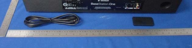
Click to zoom
Application Details
- Equipment Class
- DSS - Part 15 Spread Spectrum Transmitter
- Date of Grant
- Feb 25, 2014
- Application Purpose
- Original Equipment
- Date of Application
- Feb 25, 2014
- Equipment Note
- Active Loudspeaker
- Frequency Range
- 2402.00000000 - 2480.00000000
- Company
- Meiloon Industrial Co., Ltd.
- Country
- Taiwan
Documents & Files
Document Text
Text extracted from the exhibit documents filed with the FCC. Open a document above to read the original.
Users Manual
Owner’s Manual Important Safety Instructions 1. Read these instructions. 2. Keep these instructions. 3. Heed all warnings. 4. Follow all instructions. 5. Do not use this apparatus near water. 6. Clean only with dry cloth. 7. Do not block any ventilation openings. Install in accordance with the manufacturer’s instructions. 8. Do not install near any heat sources such as radiators, heat registers, stoves, or other apparatus (including amplifiers) that produce heat. 9. Do not defeat the safety purpose of the polarized or grounding-type plug. A polarized plug has two blades with one wider than the other. A grounding type plug has two blades and a third grounding prong. The wide blade or the third prong are provided for your safety. If the provided plug does not fit into your outlet, consult an electrician for replacement of the obsolete outlet. 10. Protect the power cord from being walked on or pinched particularly at plugs, convenience receptacles, and the point where they exit from the apparatus. 11. Only use attachments/accessories specified by the manufacturer. 12. Use only with the cart, stand, tripod, bracket, or table specified by the manufacturer, or sold with the apparatus. When a cart is used, use caution when moving the cart/apparatus combination to avoid injury from tip-over. 13. Unplug this apparatus during lightning storms or when unused for long periods of time. 14. Refer all servicing to qualified service personnel. Servicing is required when the apparatus has been damaged in any way, such as power-supply cord or plug is damaged, liquid has been spilled or objects have fallen into the apparatus, the apparatus has been exposed to rain or moisture, does not operate normally, or has been dropped. 15. The equipment shall be used at maximum 35 degree C ambient temperature. 16. Do not open the equipment to reduce the risk of electrical shock. For safety reasons it is only allowed to be opened by qualified service personnel. 17. WARNING: To reduce the risk of fire or electric shock, do not expose this apparatus to rain or moisture. And the apparatus shall not be exposed to dripping or splashing and that no objects filled with liquids, such as vases, shall be placed on the apparatus. 18. The AC inlet is used as the disconnect device and shall remain readily operable. 19. The product shall be used on an open bench. 20. No naked flame source, such as lit candles, should be placed on the apparatus. The lightning flash with arrowhead symbol within an equilateral triangle, is intended to alert the user to the presence of uninsulated “dangerous voltage” within the product’s enclosure that may be of sufficient magnitude to constitute a risk of electric shock to persons. The exclamation point within an equilateral triangle is intended to alert the user to the presence of important operating and maintenance (servicing) instructions in the literature accompanying the product. Le symbole d’éclair à tête de flèche dans un triangle équilatéral sert à prévenir l’utilisateur de la présence dans l’enceinte du produit d’une « tension dangereuse » non isolée d’une grandeur suffisante pour constituer un risque d’électrocution pour les personnes. Le point d’exclamation dans un triangle équilatéral sert à prévenir l’utilisateur de la présence d’instructions importantes de fonctionnement et de maintenance (entretien) dans les documents accompagnant l’appareil. CAUTIONATTENTION BEFORE OPENING PULL MAIN PLUG DEBRANCHER CORDON SECTEUR AVANT D’OUVRIR Le symbole d’éclair à tête de flèche dans un triangle équilatéral sert à prévenir l’utilisateur de la présence dans l’enceinte du produit d’une « tension dangereuse » non isolée d’une grandeur suffisante pour constituer un risque d’électrocution pour les personnes. Le point d’exclamation dans un triangle équilatéral sert à prévenir l’utilisateur de la présence d’instructions importantes de fonctionnement et de maintenance (entretien) dans les documents accompagnant l’appareil. CAUTIONATTENTION BEFORE OPENING PULL MAIN PLUG DEBRANCHER CORDON SECTEUR AVANT D’OUVRIR Das Blitzsymbol in einem gleichschenkligen Dreieck weist den Anwender auf eine nicht isolierte und potenziell gefährliche Spannungsquelle im Gehäuse des Gerätes hin, die stark genug sein kann, um bei Anwendern einen Stromschlag auszulösen. Ein Ausrufezeichen in einem gleichschenkligen Dreieck weist den Anwender auf wichtige Anweisungen zu Betrieb und Instandhaltung des Produkts in den begleitenden Unterlagen hin. ACHTUNGATTENTION VOR DEM ÖFFNEN NETZSTECKER ZIEHEN. DEBRANCHER CORDON SECTEUR AVANT D’OUVRIR ATENCIÓNATTENTION DESCONECTE SIEMPRE EL CABLE DE ALIMENTACIÓN ANTES DE ABRIR ESTA UNIDAD DEBRANCHER CORDON SECTEUR AVANT D’OUVRIR El símbolo de un rayo dentro de un triángulo equilátero se usa internacionalmente para advertir al usuario de la presencia de “voltajes peligrosos” no aislados dentro de la carcasa del aparato que pueden ser de magnitud suficiente para constituir un riesgo real de descarga eléctrica para las personas. El símbolo de exclamación dentro de un triángulo equilátero se utiliza para advertir al usuario de la existencia de importantes instrucciones de uso y mantenimiento (reparaciones) en los documentos que acompañan a la unidad. CAUTION RISK OF ELECTRIC SHOCK! DO NOT OPEN! ATTENTION! RISQUE DE CHOC! ELECTRIQUE PAS OUVRIR! English FCC Statement This equipment has been tested and found to comply with the limits for a Class B digital device, pursuant to Part 15 of the FCC Rules. These limits are designed to provide reasonable protection against harmful interference in a residential installation. This equipment generates uses and can radiate radio frequency energy and, if not installed and used in accordance with the instructions, may cause harmful interference to radio communications. However, there is no guarantee that interference will not occur in a particular installation. If this equipment does cause harmful interference to radio or television reception, which can be determined by …
Text truncated - open the document above for the full version.
Cover Letter(s)
Meiloon Industrial Co., Ltd. No.77, Lane 1775, Chuen-Ryh Road, Taoyuan City, Taiwan To: SIEMIC, INC. 775 Montague Expressway. Milpitas, CA 95035, USA Dear Sir/Madam, Re: Project and Product Certification Representative Authorization Letter We, Meiloon Industrial Co., Ltd. hereby authorize SIEMIC, INC. to act as a Certification Body for certifying for the following project(s): FCC ID: R48-STATIONONE Product: Active Loudspeaker Model No.: BaseStation One We affirm that between SIEMIC and Meiloon Industrial Co., Ltd., any difference in understanding, including test plan, measurement methods, applicable standards and relevant procedures and processes have been resolved prior to commencement of testing activities. Sincerely, signature : name / title : Peter Pan / Electric Engineer information / address: Meiloon Industrial Co., Ltd. (No.77, Lane 1775, Chuen-Ryh Road, Taoyuan City, Taiwan)
Cover Letter(s)
Meiloon Industrial Co., Ltd. No.77, Lane 1775, Chuen-Ryh Road, Taoyuan City, Taiwan SCS-F19: Confidentiality Request Letter Page 1 of 1 Rev 3.0 Confidentiality Letter To: Federal Communications Commission Authorization and Evaluation Division 7435 Oakland Mills Road Columbia, MD Subject: Permanent Confidentiality Request for FCC ID: R48-STATIONONE Product: Active Loudspeaker Model No.: BaseStation One We hereby request confidential treatment of information accompanying this application as outlined below: Block Diagram Schematics Operational Description The above materials contain trade secrets and proprietary information not customarily released to the public. The public disclosure of these materials may be harmful to the applicant and provide unjustified benefits to its competitors. The applicant understands that pursuant to Section 0.457 & 0.459 of the Rules, disclosure of this application and all accompanying documentation will not be made before the date of the Grant for this application. Sincerely, signature : name / title : Peter Pan / Electric Engineer information / address: Meiloon Industrial Co., Ltd. (No.77, Lane 1775, Chuen-Ryh Road, Taoyuan City, Taiwan)
ID Label/Location Info
Label Location
Internal Photos
Antenna location
RF Exposure Info
FCC ID: R48-STATIONONE 1. RF EXPOSURE EVALUATION 1.1. Limits The criteria listed in the following table shall be used to evaluate the environment impact of human exposure to radio frequency (RF) radiation as specified in 1.1307(b) Limits for Maximum Permissible Exposure (MPE) f = frequency in MHz Friis transmission formula: Pd = (Pout*G)/(4*pi*r 2 ) Where Pd = power density in mW/cm 2 , Pout = output power to antenna in mW; G = gain of antenna in linear scale, Pi = 3.1416; R = distance between observation point and center of the radiator in cm Pd id the limit of MPE, 1 mW/cm 2 . If we know the maximum gain of the antenna and the total power input to the antenna, through the calculation, we will know the distance r where the MPE limit is reached. FCC ID: R48-STATIONONE 1.2. Test Procedure Software provided by client enabled the EUT to transmit and receive data at lowest, middle and highest channel individually. 1.3. Test Result of RF Exposure Evaluation Channel Frequency (MHz) Output power to antenna (mW) Power Density at R=20cm (mW/cm 2 ) Limit (mW/cm 2 ) Result 2402 1.32 0.00033 1.0 Pass 2441 1.28 0.00032 1.0 Pass GFSK 2480 1.30 0.00033 1.0 Pass 2402 1.26 0.00032 1.0 Pass 2441 1.24 0.00031 1.0 Pass Pi/4DQP SK 2480 1.25 0.00031 1.0 Pass 2402 1.28 0.00032 1.0 Pass 2441 1.24 0.00031 1.0 Pass 8-QPSK 2480 1.25 0.00040 1.0 Pass
Test Report
FCC ID: R48-STATIONONE Keyway Testing Technology Co., Ltd. Report No. 14KWE021170R Page 1 of 37 FCC TEST REPORT(Bluetooth) for Meiloon Industrial Co., Ltd. Active Loudspeaker Model Number: BaseStation One FCC ID: R48-STATIONONE Prepared for : Meiloon Industrial Co., Ltd. Address : No.77, Lane 1775, Chuen-Ryh Road, Taoyuan City, Taiwan Prepared by : Keyway Testing Technology Co., Ltd. Address : Baishun Industrial Zone, Zhangmutou Town, Dongguan, Guangdong, China Tel: 86-769-8718 2258 Fax: 86-769-8718 1058 Report No. : 14KWE021170R Date of Test : Feb. 13-19, 2014 Date of Report : Feb. 20, 2014 FCC ID: R48-STATIONONE Keyway Testing Technology Co., Ltd. Report No. 14KWE021170R Page 2 of 37 TABLE OF CONTENTS Test Report Declaration Page 1. TEST SUMMARY .......................................................................................................................... 4 2. GENERAL PRODUCT INFORMATION......................................................................................... 4 2.1. Product Function.................................................................................................................... 4 2.2. Description of Device (EUT) .................................................................................................. 4 2.3. Difference between Model Numbers...................................................................................... 4 2.4. Independent Operation Modes .............................................................................................. 4 2.5. Test Supporting System......................................................................................................... 4 3. TEST SITES .................................................................................................................................. 5 3.1. Test Facilities ......................................................................................................................... 5 3.2. List of Test and Measurement Instruments............................................................................ 6 4. TEST SET-UP AND OPERATION MODES .................................................................................. 7 4.1. Principle of Configuration Selection .......................................................................................7 4.2. Block Diagram of Test Set-up ................................................................................................ 7 4.3. Test Operation Mode and Test Software ............................................................................... 7 4.4. Special Accessories and Auxiliary Equipment ....................................................................... 7 4.5. Countermeasures to Achieve EMC Compliance.................................................................... 7 5. EMISSION TEST RESULTS ......................................................................................................... 8 5.1. Conducted Emission at the Mains Terminals Test................................................................. 8 5.2. Radiated Emission Test ....................................................................................................... 10 6. 20DB OCCUPY BANDWIDTH..................................................................................................... 15 6.1. Limits.................................................................................................................................... 15 6.2. Test setup ............................................................................................................................ 15 7. FREQUENCY SEPARATION ...................................................................................................... 19 7.1. Limits.................................................................................................................................... 19 7.2. Test setup ............................................................................................................................ 19 8. MAXIMUM PEAK OUTPUT POWER .......................................................................................... 21 8.1. Limits.................................................................................................................................... 21 8.2. Test setup ............................................................................................................................ 21 9. NUMBER OF HOPPING FREQUENCY ...................................................................................... 22 9.1. Limits.................................................................................................................................... 22 9.2. Test setup ............................................................................................................................ 22 10. DWELL TIME ........................................................................................................................... 23 10.1. Limits.................................................................................................................................... 23 10.2. Test setup ............................................................................................................................ 23 11. BAND EDGE COMPLIANCE TEST......................................................................................... 26 11.1. Limits.................................................................................................................................... 26 11.2. Test setup ............................................................................................................................ 26 12. ANTENNA REQUIREMENTS.................................................................................................. 31 12.1. Limits...........................................................................................................................…
Text truncated - open the document above for the full version.
Test Setup Photos
Set-up for Conducted Emission Test Set-up for Radiated Emission Test
Contact Information
Applicant
Peter Pan(Electric Engineer)
Test Firm
Keyway Technology Co., LtdJade Yang
Technical Specifications
| # | Rule Parts | Frequency Range | Power Output |
|---|---|---|---|
| 1 | 15C | 2.40 GHz - 2.48 GHz | 1.00 mW |
Other Applications from Meiloon Industrial Co., Ltd.
R48-SB218
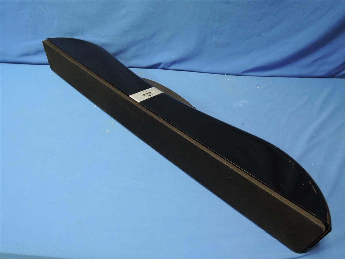
Oct 29, 2015SoundBar Speaker
Equipment Class
NII - Unlicensed National Information Infrastructure TX
R48RKBTR2X
Aug 24, 2015Tabletop Stereo
Equipment Class
DSS - Part 15 Spread Spectrum Transmitter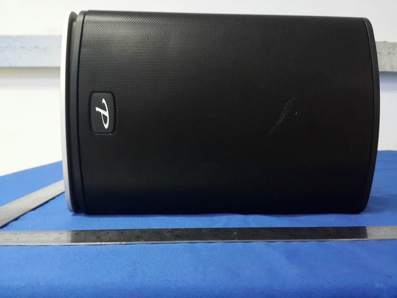
R48TT025
Aug 02, 2015active loudspeaker
Equipment Class
NII - Unlicensed National Information Infrastructure TX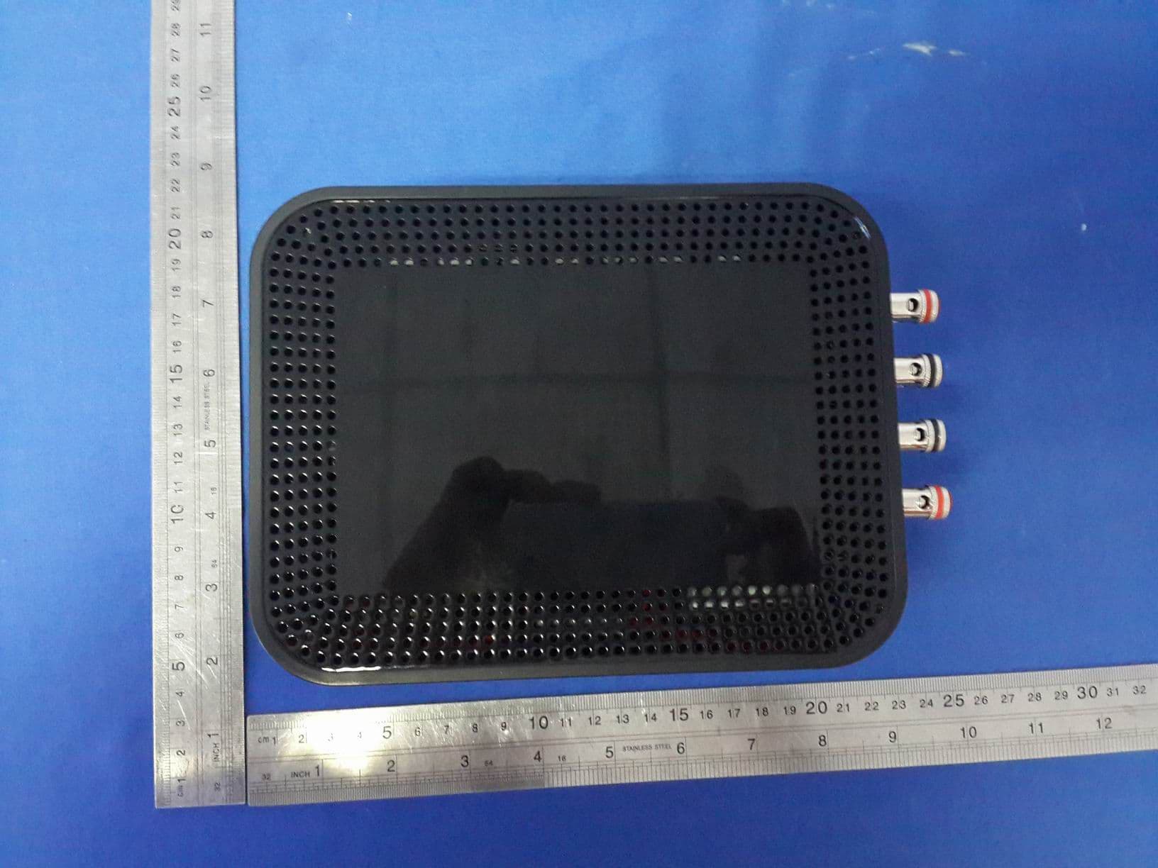
R48MP025
Jul 27, 2015active loudspeaker
Equipment Class
NII - Unlicensed National Information Infrastructure TX
R48RKBTMR1
Apr 08, 2015Active Bluetooth Speakers
Equipment Class
DSS - Part 15 Spread Spectrum Transmitter