R48RKBTMR1Active Bluetooth Speakers
Meiloon Industrial Co., Ltd.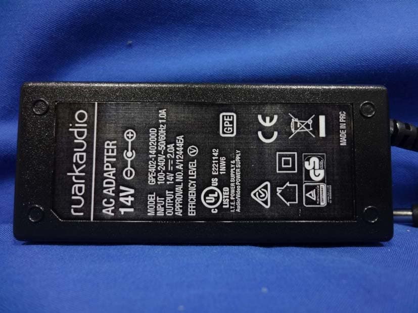
Click to zoom
Application Details
- Equipment Class
- DSS - Part 15 Spread Spectrum Transmitter
- Date of Grant
- Apr 08, 2015
- Application Purpose
- Original Equipment
- Date of Application
- Apr 07, 2015
- Equipment Note
- Active Bluetooth Speakers
- Frequency Range
- 2402.00000000 - 2480.00000000
- Company
- Meiloon Industrial Co., Ltd.
- Country
- Taiwan
Documents & Files
Document Text
Text extracted from the exhibit documents filed with the FCC. Open a document above to read the original.
Users Manual
User guide Brugervejledning Bedienungsanleitung Manual de instrucciones Guide de l’utilisateur Manuale utente Gebruikershandleiding Brukerveiledning EN DA DE ES FR IT NL NO Active Bluetooth Speakers MR1 RA MR1 User Guide.indd 131/03/2015 09:46:42 EN-2 Thank you for choosing our MR1 active Bluetooth speakers. With our heritage designing high-fidelity loudspeaker systems for audio enthusiasts, we’re fanatical about sound quality. With this in mind, we’ve created these compact multipurpose loudspeakers to give everyone access to high quality sound, with the additional convenience of Bluetooth connectivity. We think they’re great and we hope you enjoy them as much as we do. With due care, we’re confident our MR1s will give you many years of listening pleasure, so please take the time to read this user guide as it will help you to set them up and get the best performance from them. Once again, thank you for choosing Ruark Audio. Alan O’Rourke Founder and Managing Director RA MR1 User Guide.indd 231/03/2015 09:46:42 EN-3 EN DA DE FR IT ES NL NO Ensure that all parts listed below are in the box. If any part is missing do not use the speakers and contact us directly if purchased in the UK, or your Ruark Audio dealer if purchased outside the UK. 1. Left speaker 2. Right speaker 3. AC power adaptor 4. Plug(s) for AC power adapter* 5. Speaker interconnect cable 6. Remote control 7. User guide & other documents Please retain carton and all packing materials. 1 What’s in the box 1 3457 6 2 * The number and type of plug adapters supplied will vary according to region. RA MR1 User Guide.indd 331/03/2015 09:46:42 EN-4 Right speaker back 13. Output to left speaker 14. DC power socket 15. Sub-woofer output (3.5mm stereo jack) 16. Line-in audio input (3.5mm stereo jack) 17. Input level select Right speaker front 8. Control knob (volume and source) 9. Status indicator light (see section 8) 10. Tweeter (high frequency driver) 11. Remote sensor 12. Woofer (low frequency driver) 2 Overview 8 10 9 16 17 15 14 13 11 12 short press = power long press = source RA MR1 User Guide.indd 431/03/2015 09:46:42 EN-5 EN DA DE FR IT ES NL NO 3 Remote control Changing battery 1. Hold the lock to the side with your finger and slide the battery compartment out. 2. With the remote face down, replace the battery with a new CR2025, ensuring the flat side marked with + faces up. 3. Push the battery compartment back into place. 18. Standby 19. Mute 20. Line in 21. Volume 22. Bluetooth 23. Battery tab NOTE: before using your remote for the first time you must remove the clear plastic tab (23) to activate the battery. Specifications Speakers Ruark 75mm neodymium woofers Ruark 20mm soft dome tweeters 20W Linear amplifier Audio grade crossover components Bluetooth: A2DP, aptX Power consumption: 10-12W typical (28W max) Power consumption (standby): 0.5W Line-in input: 3.5mm stereo jack Sub-woofer output: Line level 3.5mm stereo jack Dimensions: 175 x 130 x 135mm (6.9 x 5.1 x 5.3ins) Weight (incl. packaging): 3.5kg (7.7lbs) Power adapter Input: 100-240VAC 50-60Hz 1.0A max Output: 14VDC 2.0A 18 21 22 23 19 20 RA MR1 User Guide.indd 531/03/2015 09:46:42 EN-6 4 Setup 1 Position speakers For best stereo reproduction, place left and right speakers no less than 60cm (24in) apart with the speaker with volume control on the right. Avoid having objects in front of the speakers and also ensure the underside of each speaker is unobstructed. 2 Connect speakers together Connect the two speakers with the interconnect cable (5), inserting one end into the output (13) on the right speaker and the other end into the input socket on the left speaker. 3 Connect to AC power Fit the correct plug (4) for your region to the mains power supply. When you fit the plug adapter, it will “click” into place. Connect the DC cable from the power supply to the DC power socket on the back of your MR1. Plug the AC power adapter into a mains power socket. CAUTION: do not plug the AC power cord into the mains until all other connections are made. 4 Turn on your speakers When you connect the speakers to mains power they will power up in standby mode. To turn them on, press the control knob (8) on the right speaker or the standby button (18) on the remote; the source status indicator (9) glows solid amber showing that Line-in audio input is selected. 5 Adjust volume Turn the volume control knob (8) clockwise to increase the volume, anticlockwise to decrease it or use the volume buttons (21) on the remote. When you reach the maximum or minimum volume, the status indicator (9) goes off temporarily. 6 Standby Press and release (short press) the control knob (8)or press the standby button (18) on the remote. RA MR1 User Guide.indd 631/03/2015 09:46:42 EN-7 EN DA DE FR IT ES NL NO 1 Connect your device To connect you will need a lead with a 3.5mm stereo jack on one end to connect to the Line-in input socket (16) and an appropriate connector on the other to connect to the Line-out or headphone output of the device you wish to connect, MP3/CD Player, Laptop or TV etc. 2 Select Line-in audio input When the status indicator (9) is amber, the audio input is set to Line-in. If the status indicator (9) is blue the speakers are in Bluetooth mode, in which case press and hold the control knob (8) or press the Line-in button (20) on the remote control to change to Bluetooth mode. If the status indicator (9) is off, the speakers are in standby, in which case press the control knob (8), or press the Line-in button (20) on the remote control to turn them on. 3 Start music play on your device Adjusting input level Unless you experience audio distortion, we recommend you keep the output volume on your device near maximum and the input level switch (17) set to LOW. Some computer headphone or audio outputs may have high signal levels. If the sound is distorted, turn down the volume level on the device. Other audio devices, such as CD/DVD/Blu-ray players, may also have high output signals but witho…
Text truncated - open the document above for the full version.
Cover Letter(s)
RF_160, Issue 03 Meiloon Industrial Co., Ltd. Declaration of Authorization We Name: Meiloon Industrial Co., Ltd. Address: No.77, Lane 1775, Chuen-Ryh Road, Taoyuan City, Taiwan City: Taoyuan City Country: Taiwan Declare that: Name Representative of agent: Gene Chang (1) Agent Company name: QuieTek Corp. Address: Fl.2, No.345, Xin-hu 2 nd Rd., Nei-hu District City: Taipei Country Taiwan is authorized to apply for Certification of the following product(s): Product description: Active Bluetooth Speakers FCC ID: R48RKBTMR1 Trademark: ruarkaudio on our behalf. Date: 2015/01/16 City: Taoyuan City Name: Peter Pan (2) Function: Electric Engineer Signature: Notes: (1): Required for FCC application (2): For FCC it must be the Grantee Code “owner” or the authorized agent.
External Photos
Report No.: 1490385R-RFUSP01V00 Page : 1 of 13 Attachment 2 : EUT Detailed Photographs (1) EUT Photo (2) EUT Photo Report No.: 1490385R-RFUSP01V00 Page : 2 of 13 (3) EUT Photo (4) EUT Photo
ID Label/Location Info
Meiloon Industrial Co., Ltd. FCC ID.: R48RKBTMR1 No.77, Lane 1775, Chuen-Ryh Road, Taoyuan City, Taiwan Tel : +886-3-326-1611 FCC ID Label
ID Label/Location Info
Meiloon Industrial Co., Ltd. FCC ID.: R48RKBTMR1 No.77, Lane 1775, Chuen-Ryh Road, Taoyuan City, Taiwan Tel : +886-3-326-1611 The FCC ID Label will be placed on the equipment as shown in the photograph below.
Internal Photos
Report No.: 1490385R-RFUSP01V00 Page : 3 of 13 (5) EUT Photo (6) EUT Photo Report No.: 1490385R-RFUSP01V00 Page : 4 of 13 (7) EUT Photo (8) EUT Photo Report No.: 1490385R-RFUSP01V00 Page : 5 of 13 (9) EUT Photo (10) EUT Photo Antenna Report No.: 1490385R-RFUSP01V00 Page : 6 of 13 (11) EUT Photo (12) EUT Photo Report No.: 1490385R-RFUSP01V00 Page : 7 of 13 (13) EUT Photo (14) EUT Photo Report No.: 1490385R-RFUSP01V00 Page : 8 of 13 (15) EUT Photo (16) EUT Photo Report No.: 1490385R-RFUSP01V00 Page : 9 of 13 (17) EUT Photo (18) EUT Photo Report No.: 1490385R-RFUSP01V00 Page : 10 of 13 (19) EUT Photo (20) EUT Photo Report No.: 1490385R-RFUSP01V00 Page : 11 of 13 (21) EUT Photo (22) EUT Photo Report No.: 1490385R-RFUSP01V00 Page : 12 of 13 (23) EUT Photo (24) EUT Photo Report No.: 1490385R-RFUSP01V00 Page : 13 of 13 (25) EUT Photo (26) EUT Photo
RF Exposure Info
Report No. 1490385R-RFUSP01V00 Page: 1 of 3 RF Exposure Evaluation declaration Product Name Active Bluetooth Speakers Model No. MR1 FCC ID R48RKBTMR1 Applicant Meiloon Industrial Co., Ltd. Address No.77, Lane 1775, Chuen-Ryh Road, Taoyuan City, Taiwan Date of Receipt Sep. 16, 2014 Date of Declaration Dec. 29, 2014 Report No. 1490385R-RFUSP01V00 The test results relate only to the samples tested. The test results shown in the test report are traceable to the national/international standard through the calibration of the equipment and evaluated measurement uncertainty herein. This report must not be used to claim product endorsement by TAF or any agency of the government. The test report shall not be reproduced without the written approval of QuieTek Corporation. Report No. 1490385R-RFUSP01V00 Page: 2 of 3 1. RF Exposure Evaluation 1.1. Limits According to FCC 1.1310: The criteria listed in the following table shall be used to evaluate the environment impact of human exposure to radio frequency (RF) radiation as specified in 1.1307(b) LIMITS FOR MAXIMUM PERMISSIBLE EXPOSURE (MPE) Frequency Range (MHz) Electric Field Strength (V/m) Magnetic Field Strength (A/m) Power Density (mW/cm 2 ) Average Time (Minutes) (A) Limits for Occupational/ Control Exposures 300-1500 -- -- F/300 6 1500-100,000 -- -- 5 6 (B) Limits for General Population/ Uncontrolled Exposures 300-1500 -- -- F/1500 6 1500-100,000 -- -- 1 30 F= Frequency in MHz Friis Formula Friis transmission formula: Pd = (Pout*G)/(4*pi*r 2 ) Where Pd = power density in mW/cm 2 Pout = output power to antenna in mW G = gain of antenna in linear scale Pi = 3.1416 R = distance between observation point and center of the radiator in cm Pd id the limit of MPE, 1 mW/cm 2 . If we know the maximum gain of the antenna and the total power input to the antenna, through the calculation, we will know the distance r where the MPE limit is reached. 1.2. Test Procedure Software provided by client enabled the EUT to transmit and receive data at lowest, middle and highest channel individually. The temperature and related humidity: 18°Cand 78% RH. Report No. 1490385R-RFUSP01V00 Page: 3 of 3 1.3. Test Result of RF Exposure Evaluation Product : Active Bluetooth Speakers Test Item : RF Exposure Evaluation Test Site : No.3 OATS Operation Frequency 2402-2480MHz Maximum Conducted output power 4.48dBm Antenna gain -0.46dBi Output Power Into Antenna & RF Exposure Evaluation Distance: Output Power to Antenna (mW) Power Density at R = 20 cm (mW/cm2) 2.8054 0.000502 Power density is lower than the limit (1 mW/cm2).
Test Report
Report No. 1490385R-RFUSP01V00 Page: 1 of 64 FCC Test Report Product Name Active Bluetooth Speakers Model No. MR1 FCC ID. R48RKBTMR1 Applicant Meiloon Industrial Co., Ltd. Address No.77, Lane 1775, Chuen-Ryh Road, Taoyuan City, Taiwan Date of Receipt Sep. 16, 2014 Issued Date Dec. 29, 2014 Report No. 1490385R-RFUSP01V00 Report Version V1.0 The test results relate only to the samples tested. The test results shown in the test report are traceable to the national/international standard through the calibration report of the equipment and evaluated measurement uncertainty herein. This report must not be used to claim product endorsement by TAF or any agency of the government. The test report shall not be reproduced without the written approval of QuieTek Corporation. Report No. 1490385R-RFUSP01V00 Page: 2 of 64 Test Report Issued Date: Dec. 29, 2014 Report No.: 1490385R-RFUSP01V00 Product Name Active Bluetooth Speakers Applicant Meiloon Industrial Co., Ltd. Address No.77, Lane 1775, Chuen-Ryh Road, Taoyuan City, Taiwan Manufacturer Meiloon Industrial Co., Ltd. Model No. MR1 FCC ID. R48RKBTMR1 EUT Rated Voltage AC 100-240V, 50/60Hz EUT Test Voltage AC 120V/60Hz Trade Name ruarkaudio Applicable Standard FCC CFR Title 47 Part 15 Subpart C: 2013 ANSI C63.10: 2009 Test Result Complied Documented By : ( Senior Adm. Specialist / Joanne Lin ) Reviewed By : ( Engineer / Eason Chen ) Approved By : ( Director / Vincent Lin ) Report No. 1490385R-RFUSP01V00 Page: 3 of 64 TABLE OF CONTENTS Description Page 1. GENERAL INFORMATION ...............................................................................................................5 1.1. EUT Description......................................................................................................................................5 1.2. Operational Description...........................................................................................................................7 1.3. Tested System Details..............................................................................................................................8 1.4. Configuration of Tested System ..............................................................................................................8 1.5. EUT Exercise Software ...........................................................................................................................8 1.6. Test Facility .............................................................................................................................................9 2. CONDUCTED EMISSION ................................................................................................................10 2.1. Test Equipment ......................................................................................................................................10 2.2. Test Setup ..............................................................................................................................................10 2.3. Limits.....................................................................................................................................................11 2.4. Test Procedure .......................................................................................................................................11 2.5. Uncertainty ............................................................................................................................................11 2.6. Test Result of Conducted Emission .......................................................................................................12 3. PEAK POWER OUTPUT ..................................................................................................................14 3.1. Test Equipment ......................................................................................................................................14 3.2. Test Setup ..............................................................................................................................................14 3.3. Limit .....................................................................................................................................................14 3.4. Test Procedure .......................................................................................................................................14 3.5. Uncertainty ............................................................................................................................................14 3.6. Test Result of Peak Power Output .........................................................................................................15 4. RADIATED EMISSION .....................................................................................................................17 4.1. Test Equipment ......................................................................................................................................17 4.2. Test Setup ..............................................................................................................................................17 4.3. Limits.....................................................................................................................................................18 4.4. Test Procedure .......................................................................................................................................19 4.5. Uncertainty ............................................................................................................................................19 4.6. Test Result of Radiated Emission ..........................................................................................................20 5. RF ANTENNA CONDUCTED TEST................................................................................................28 5.1. Test Equipment ...........................…
Text truncated - open the document above for the full version.
Test Setup Photos
Report No.: 1490385R-RFUSP01V00 Page : 1 of 3 Attachment 1: EUT Test Setup Photographs Front View of Conducted Test Back View of Conducted Test Report No.: 1490385R-RFUSP01V00 Page : 2 of 3 Front View of Radiated Test Back View of Radiated Test Report No.: 1490385R-RFUSP01V00 Page : 3 of 3 Front View of Radiated Test (Horn) Back View of Radiated Test (Horn)
Contact Information
Applicant
Peter Pan(Electric Engineer)
Technical Contact
QuieTek CorporationMaggie Chen
[email protected]886-2-8601-3788
No.5-22, Ruishukeng, Linkou Dist., · Taiwan
Non-Technical Contact
QuieTek CorporationMaggie Chen
[email protected]886-2-8601-3788
Test Firm
DEKRA TESTING AND CERTIFICATION CO., LTD. LinKouMirenda Liao
Technical Specifications
| # | Rule Parts | Frequency Range | Power Output |
|---|---|---|---|
| 1 | 15C | 2.40 GHz - 2.48 GHz | 3.00 mW |
Other Applications from Meiloon Industrial Co., Ltd.
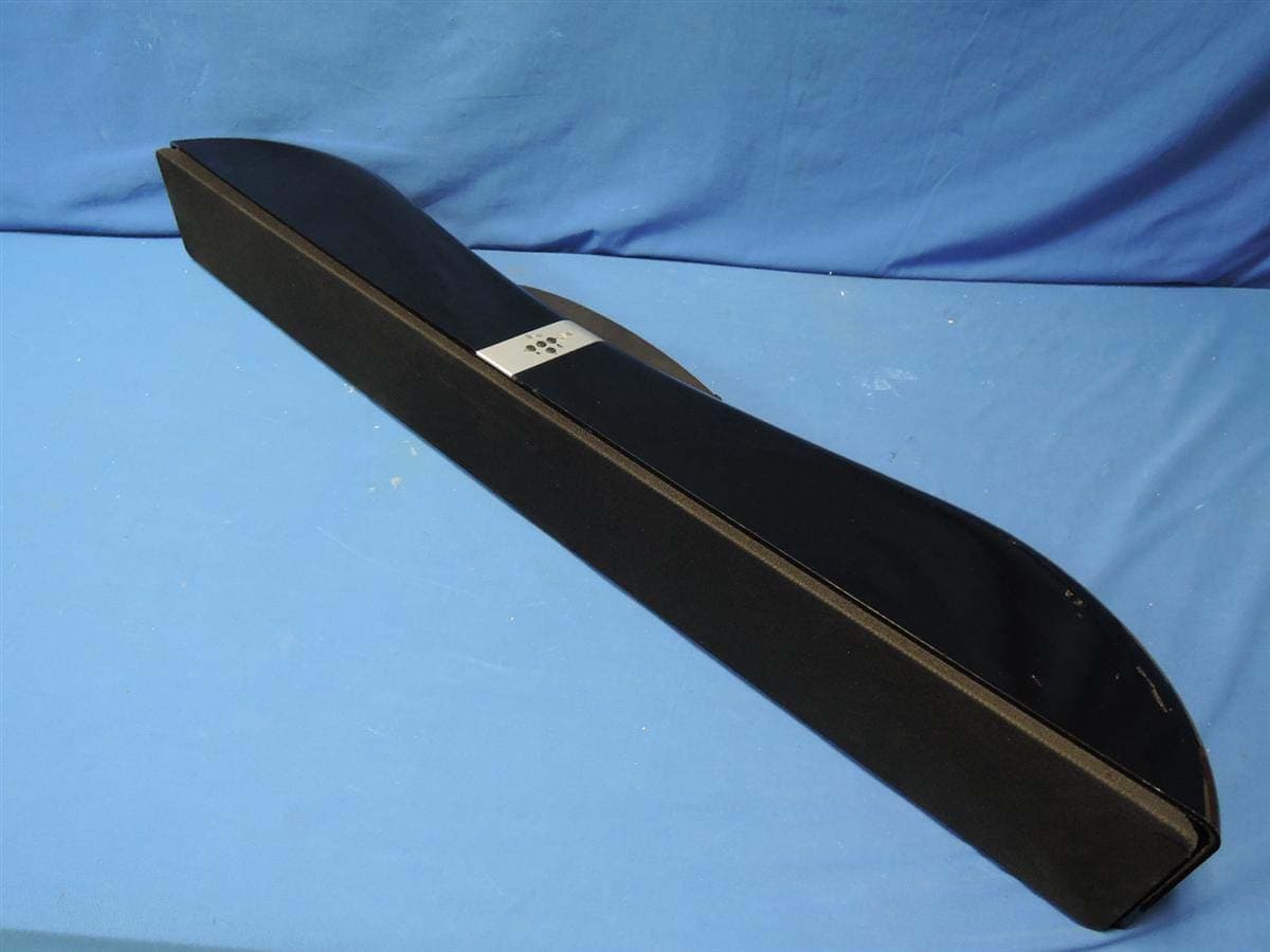
R48-SB218
Oct 29, 2015SoundBar Speaker
Equipment Class
NII - Unlicensed National Information Infrastructure TX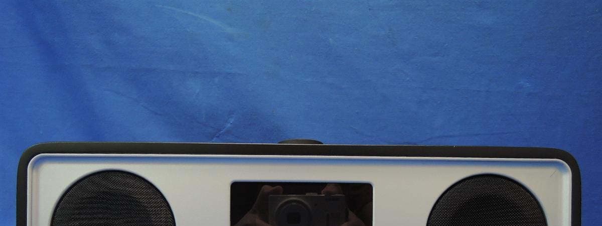
R48RKBTR2X
Aug 24, 2015Tabletop Stereo
Equipment Class
DSS - Part 15 Spread Spectrum Transmitter
R48TT025
Aug 02, 2015active loudspeaker
Equipment Class
NII - Unlicensed National Information Infrastructure TX
R48MP025
Jul 27, 2015active loudspeaker
Equipment Class
NII - Unlicensed National Information Infrastructure TX
R48V5BT14
Mar 24, 2015Bluetooth Speaker
Equipment Class
DSS - Part 15 Spread Spectrum Transmitter