R48COMBTEnergyXStream (tm)
Meiloon Industrial Co., Ltd.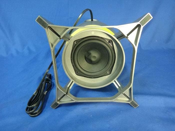
Click to zoom
Application Details
- Equipment Class
- DSS - Part 15 Spread Spectrum Transmitter
- Date of Grant
- Dec 05, 2013
- Application Purpose
- Original Equipment
- Date of Application
- Dec 05, 2013
- Equipment Note
- EnergyXStream (tm)
- Frequency Range
- 2402.00000000 - 2480.00000000
- Company
- Meiloon Industrial Co., Ltd.
- Country
- Taiwan
Documents & Files
Document Text
Text extracted from the exhibit documents filed with the FCC. Open a document above to read the original.
Users Manual
™ FIELD OPERATIONS MANUAL SECTION I: PREFACE The circulation of this document shall be limited to those persons who are authorized to have the information in the performance of their personal entertainment duties. This document contains guidelines pertaining to instruction and training in the mechanical operation of the EnergyXStream™ M-21 multimedia speaker system. Intended users include, but are not limited to, xxxxxxxxx, gamers, music enthusiasts and others who will use this document as proper fortification to engage the M-21 in a highly successful, frontal audio assault. The term “SUBWOOFER” refers to a loudspeaker designed for the specific reproduction of very low bass frequencies. The term “SATELLITE” refers to a loudspeaker designed for the specific reproduction of midrange and high frequencies. Actions regarding the placement, hookup, xxxxxxxxx and maintenance of the M-21 are as follows. Efforts were made to standardize hookup procedures and terminology. SECTION II: COMPONENT LIST COMPONENT 1: SUBWOOFER COMPONENT 2: SATELLITE, LEFT CHANNEL COMPONENT 3: SATELLITE, RIGHT CHANNEL (WITH SYSTEM CONTROLS AND CONNECTIONS) COMPONENT 4: 3.5MM TO 3.5MM CORD COMPONENT 5: RCA TO 3.5MM ADAPTER 7.63” 3.5” 19.25” 7.69”7.69” 3.5” COMPONENT 1COMPONENT 2COMPONENT 3COMPONENT 4COMPONENT 5 SECTION III: ASSEMBLY Assembly of the M-21 MUST be completed in the following manner to assure a decisive victory: SECTION IV: WIRED SOURCE CONNECTIONS The M-21 MUST be connected via the 3.5MM to 3.5MM cord (included) OR Bluetooth ® to an audio source to insure total sound infiltration. The following illustrations are examples of the most frequently used in-field connections. CONNECTION TO COMPUTER Using included 3.5mm to 3.5mm cable CONNECTION TO GAME CONSOLE Using 3.5mm to L/R RCA cable CONNECTION TO GAME CONSOLE Using included 3.5mm to 3.5mm cable Headphone Headphone Audio Out TV Console TV Console Headphone Headphone Audio Out TV Console TV Console Headphone Headphone TV Console Console
Users Manual
SECTION V: BLUETOOTH CONNECTION AND STREAMING The M-21 has the capability for engagement of Bluetooth audio streaming. Initiate by pressing the designated Bluetooth button on the right satellite rear and then activate Bluetooth on your audio source device. The M-21 will automatically switch to Bluetooth mode, allowing the commencement of music streaming. Maximum effective range for Bluetooth operation is 30 feet. Yellow to Blue LED Front Back Press Hold Bluetooth Button 3 Seconds Bluetooth Bluetooth ON M-21 Devices Settings Bluetooth Bluetooth ON 12345 M-21M-21 Devices Not PairedConnected Settings * Example only. Your device may differ. Deployment of a soft cloth to dust and/or wipe all cabinetry is required on an occasional basis for best presentation. Never use water or any type of cleaner or detergent on any part of the M-21. SECTION VI: OPERATION UNDER USUAL CONDITIONS SECTION VII: CLEANING Yellow LED (Power On) Subwoofer Volume System Volume Power On/Off Register your Energy speaker at energyspeakers.com/register. 3502 Woodview Trace Indianapolis, IN 46268 • 866.441.8208 energyspeakers.com Energy, EnergyXStream and the Energy logo are registered trademarks of Audio Products International Corp., registered in the U.S. and other countries. Audio Products International Corp. is a wholly owned subsidiary of Voxx International Corporation. The Bluetooth® word mark and logos are registered trademarks owned by Bluetooth SIG, Inc. and any use of such marks by Klipsch Group, Inc. is under license.
Users Manual
™ FIELD OPERATIONS MANUAL IMPORTANT SAFETY INSTRUCTIONS ™ IMPORTANT SAFETY INSTRUCTIONS! 1. READ these instructions. 2. KEEP these instructions. 3. HEED all warnings. 4. FOLLOW all instructions. 5. DO NOT use this apparatus near water. 6. CLEAN ONLY with dry cloth. 7. DO NOT block any ventilation openings. Install in accor- dance with the manufacturer’s instructions. 8. DO NOT install near any heat sources such as radiators, heat registers, stoves, or other apparatus (including amplifiers) that produce heat. 9. DO NOT defeat the safety purpose of the polarized or grounding type plug. A polarized plug has two blades with one wider than the other. A grounding type plug has two blades and a third grounding prong. The wider blade or the third prong are provided for your safety. If the provided plug does not fit into your outlet, consult an electrician for replacement of the obsolete outlet. 10. PROTECT the power cord from being walked on or pinched, particularly at plugs, convenience receptacles, and the point where they exit from the apparatus. 11. ONLY USE attachments/accessories specified by the manufacturer. 12. USE ONLY with a cart, stand, tripod, bracket, or table specified by the manufacturer, or sold with the apparatus. When a cart is used, use caution when moving the cart/apparatus combination to avoid injury from tip-over. 13. UNPLUG this apparatus during lightning storms or when unused for long periods of time. 14. REFER all servicing to qualified service personnel. Servic- ing is required when the apparatus has been damaged in any way, such as power-supply cord or plug is damaged, liquid has been spilled or objects have fallen into the ap- paratus, the apparatus has been exposed to rain or mois- ture, does not operate normally, or has been dropped. 15. DO NOT expose this apparatus to dripping or splashing and ensure that no objects filled with liquids, such as vases, are placed on the apparatus. 16. To completely disconnect this apparatus from the AC Mains, disconnect the power supply cord plug from the AC receptacle. Language 17. The mains plug of the power supply cord shall remain readily operable. 18. DO NOT overload wall outlets or extension cords beyond their rated capacity as this can cause electric shock or fire. The exclamation point, within an equilateral triangle, is intended to alert the user to the presence of important operating and maintenance (servicing) instructions in the literature accompanying the product. The lightning flash with arrowhead symbol within an equilateral triangle is intended to alert the user to the presence of uninsulated “dangerous voltage” within the product’s enclosure that may be of sufficient magnitude to constitute a risk of electrical shock to persons. WARNING: To reduce the risk of fire or electrical shock, do not expose this apparatus to rain or moisture. WARNING: No naked flame sources – such as candles – should be placed on the product. WARNING: Do Not Open! Risk of Electrical Shock. Voltages in this equipment are hazardous to life. No user-serviceable parts inside. Refer all servicing to qualified service personnel. Place the equipment near a main power supply outlet and make sure that you can easily access the power breaker switch. WARNING: This product is intended to be operated ONLY from the AC Voltages listed on the back panel or included power sup- ply of the product. Operation from other voltages other than those indicated may cause irreversible damage to the product and void the products warranty. The use of AC Plug Adapters is cautioned because it can allow the product to be plugged into voltages in which the product was not designed to operate. If the product is equipped with a detachable power cord, use only the type provided with your product or by your local distributor and/or retailer. If you are unsure of the correct operational voltage, please contact your local distributor and/or retailer. Language FCC AND CANADA EMC COMPLIANCE INFORMATION This device complies with part 15 of the FCC Rules. Operation is subject to the following two conditions: (1) This device may not cause harmful interference, and (2) this device must accept any interference received, including interference that may cause undesired operation. NOTE: This equipment has been tested and found to comply with the limits for a Class B digital device, pursuant to part 15 of the FCC Rules. These limits are designed to provide reason- able protection against harmful interference in a residential installation. This equipment generates, uses and can radiate radio frequency energy and, if not installed and used in accordance with the instructions, may cause harmful interfer- ence to radio communications. However, there is no guarantee that interference will not occur in a particular installation. If this equipment does cause harmful interference to radio or television reception, which can be determined by turning the equipment off and on, the user is encouraged to try to correct the interference by one or more of the following measures: • Reorient or relocate the receiving antenna. • Increase the separation between the equipment and receiver. • Connect the equipment into an outlet on a circuit different from that to which the receiver is connected. • Consult the dealer or an experienced radio/TV technician for help. Approved under the verification provision of FCC Part 15 as a Class B Digital Device. Caution: Changes or modifications not expressly approved by the manufacturer could void the user’s authority to operate this device. Caution: To comply with the limits of the Class B digital device, pursuant to Part 15 of the FCC Rules, this device is to comply with Class B limits. All peripherals must be shielded and grounded. Operation with non-certified peripherals or non- shielded cables my result in interference to radio or reception. This Class B digital apparatus complies with Canadian ICES-003. Cet appareil numérique de la classe B est conforme à la norme NMB…
Text truncated - open the document above for the full version.
External Photos
Report No.: 13A0067R-RFUSP43V01 Page : 1 of 27 Attachment 2 : EUT Detailed Photographs (1) EUT Photo (2) EUT Photo Report No.: 13A0067R-RFUSP43V01 Page : 2 of 27 (3) EUT Photo (4) EUT Photo Report No.: 13A0067R-RFUSP43V01 Page : 3 of 27 (5) EUT Photo (6) EUT Photo
ID Label/Location Info
Meiloon Industrial Co., Ltd. FCC ID.: R48COMBT No.77, Lane 1775, Chuen-Ryh road, Taoyuan City, TaiwanTel : 886-33261611 FCC ID Label
ID Label/Location Info
Meiloon Industrial Co., Ltd. FCC ID.: R48COMBT No.77, Lane 1775, Chuen-Ryh road, Taoyuan City, TaiwanTel : 886-33261611 The FCC ID will be placed on the equipment as shown in the photograph below.
Internal Photos
Report No.: 13A0067R-RFUSP43V01 Page : 4 of 27 (7) EUT Photo (8) EUT Photo Report No.: 13A0067R-RFUSP43V01 Page : 5 of 27 (9) EUT Photo (10) EUT Photo Report No.: 13A0067R-RFUSP43V01 Page : 6 of 27 (11) EUT Photo (12) EUT Photo Report No.: 13A0067R-RFUSP43V01 Page : 7 of 27 (13) EUT Photo (14) EUT Photo Report No.: 13A0067R-RFUSP43V01 Page : 8 of 27 (15) EUT Photo (16) EUT Photo Report No.: 13A0067R-RFUSP43V01 Page : 9 of 27 (17) EUT Photo (18) EUT Photo Antenna Report No.: 13A0067R-RFUSP43V01 Page : 10 of 27 (19) EUT Photo (20) EUT Photo BT Module Report No.: 13A0067R-RFUSP43V01 Page : 11 of 27 (21) EUT Photo (22) EUT Photo Report No.: 13A0067R-RFUSP43V01 Page : 12 of 27 (23) EUT Photo (24) EUT Photo Report No.: 13A0067R-RFUSP43V01 Page : 13 of 27 (25) EUT Photo (26) EUT Photo Report No.: 13A0067R-RFUSP43V01 Page : 14 of 27 (27) EUT Photo (28) EUT Photo Report No.: 13A0067R-RFUSP43V01 Page : 15 of 27 (29) EUT Photo (30) EUT Photo Report No.: 13A0067R-RFUSP43V01 Page : 16 of 27 (31) EUT Photo (32) EUT Photo Report No.: 13A0067R-RFUSP43V01 Page : 17 of 27 (33) EUT Photo (34) EUT Photo Report No.: 13A0067R-RFUSP43V01 Page : 18 of 27 (35) EUT Photo (36) EUT Photo Report No.: 13A0067R-RFUSP43V01 Page : 19 of 27 (37) EUT Photo (38) EUT Photo Report No.: 13A0067R-RFUSP43V01 Page : 20 of 27 (39) EUT Photo (40) EUT Photo Report No.: 13A0067R-RFUSP43V01 Page : 21 of 27 (41) EUT Photo (42) EUT Photo Report No.: 13A0067R-RFUSP43V01 Page : 22 of 27 (43) EUT Photo (44) EUT Photo Report No.: 13A0067R-RFUSP43V01 Page : 23 of 27 (45) EUT Photo (46) EUT Photo Report No.: 13A0067R-RFUSP43V01 Page : 24 of 27 (47) EUT Photo (48) EUT Photo Report No.: 13A0067R-RFUSP43V01 Page : 25 of 27 (49) EUT Photo (50) EUT Photo (Antenna) Report No.: 13A0067R-RFUSP43V01 Page : 26 of 27 (51) EUT Photo (52) EUT Photo Report No.: 13A0067R-RFUSP43V01 Page : 27 of 27 (53) EUT Photo (54) EUT Photo
Test Report
Report No. 13A0067R-RFUSP43V01 Page: 1 of 68 FCC Test Report Product Name EnergyXStream™ Model No. M-21 FCC ID. R48COMBT Applicant Meiloon Industrial Co., Ltd. Address No.77, Lane 1775, Chuen-Ryh road, Taoyuan City, Taiwan Date of Receipt Sep. 30, 2013 Issued Date Nov. 14, 2013 Report No. 13A0067R-RFUSP43V01 Report Version V1.0 The Test Results relate only to the samples tested. The test report shall not be reproduced except in full without the written approval of QuieTek Corporation. This report must not be used to claim product endorsement by TAF or any agency of the U.S. Government Report No. 13A0067R-RFUSP43V01 Page: 2 of 68 Test Report Certification Issued Date: Nov. 14, 2013 Report No.: 13A0067R-RFUSP43V01 Product Name EnergyXStream™ Applicant Meiloon Industrial Co., Ltd. Address No.77, Lane 1775, Chuen-Ryh road, Taoyuan City, Taiwan Manufacturer Klipsch Group, Inc. Model No. M-21 FCC ID. R48COMBT EUT Rated Voltage AC 120V/ 60Hz EUT Test Voltage AC 120V/ 60Hz Trade Name Applicable Standard FCC CFR Title 47 Part 15 Subpart C: 2012 ANSI C63.4: 2003, ANSI C63.10: 2009 Test Result Complied The Test Results relate only to the samples tested. The test report shall not be reproduced except in full without the written approval of QuieTek Corporation. This report must not be used to claim product endorsement by TAF or any agency of the U.S. Government Documented By : (Senior Adm. Specialist / Leven Huang ) Tested By : ( Engineer / Jerry Tsai ) Approved By : (Director / Vincent Lin ) Report No. 13A0067R-RFUSP43V01 Page: 3 of 68 TABLE OF CONTENTS Description Page 1. GENERAL INFORMATION ...............................................................................................................5 1.1. EUT Description......................................................................................................................................5 1.2. Operational Description...........................................................................................................................7 1.3. Tested System Details..............................................................................................................................8 1.4. Configuration of Tested System ..............................................................................................................8 1.5. EUT Exercise Software ...........................................................................................................................8 1.6. Test Facility .............................................................................................................................................9 2. CONDUCTED EMISSION ................................................................................................................10 2.1. Test Equipment ......................................................................................................................................10 2.2. Test Setup ..............................................................................................................................................10 2.3. Limits.....................................................................................................................................................11 2.4. Test Procedure .......................................................................................................................................11 2.5. Uncertainty ............................................................................................................................................11 2.6. Test Result of Conducted Emission .......................................................................................................12 3. PEAK POWER OUTPUT ..................................................................................................................14 3.1. Test Equipment ......................................................................................................................................14 3.2. Test Setup ..............................................................................................................................................14 3.3. Limit .....................................................................................................................................................14 3.4. Test Procedure .......................................................................................................................................14 3.5. Uncertainty ............................................................................................................................................14 3.6. Test Result of Peak Power Output .........................................................................................................15 4. RADIATED EMISSION .....................................................................................................................17 4.1. Test Equipment ......................................................................................................................................17 4.2. Test Setup ..............................................................................................................................................17 4.3. Limits.....................................................................................................................................................18 4.4. Test Procedure .......................................................................................................................................19 4.5. Uncertainty ............................................................................................................................................19 4.6. Test Result of Radiated Emission ..........................................................................................................20 5. RF ANTENNA CONDUCTED TEST...........................................................................…
Text truncated - open the document above for the full version.
Test Setup Photos
Report No.: 13A0067R-RFUSP43V01 Page : 1 of 3 Attachment 1: EUT Test Setup Photographs Front View of Conducted Test Back View of Conducted Test Report No.: 13A0067R-RFUSP43V01 Page : 2 of 3 Front View of Radiated Test Back View of Radiated Test Report No.: 13A0067R-RFUSP43V01 Page : 3 of 3 Front View of Radiated Test (Horn) Back View of Radiated Test (Horn)
Contact Information
Applicant
Peter Pan(Electric Engineer)
Technical Contact
QuieTek CorporationMaggie Chen
[email protected]886-2-8601-3788
No. 5-22, Rueishu Keng, Linkou Dist. · New Taipei City · Taiwan
Test Firm
DEKRA TESTING AND CERTIFICATION CO., LTD. LinKouMirenda Liao
Technical Specifications
| # | Rule Parts | Frequency Range | Power Output |
|---|---|---|---|
| 1 | 15C | 2.40 GHz - 2.48 GHz | 4.90 mW |
Other Applications from Meiloon Industrial Co., Ltd.
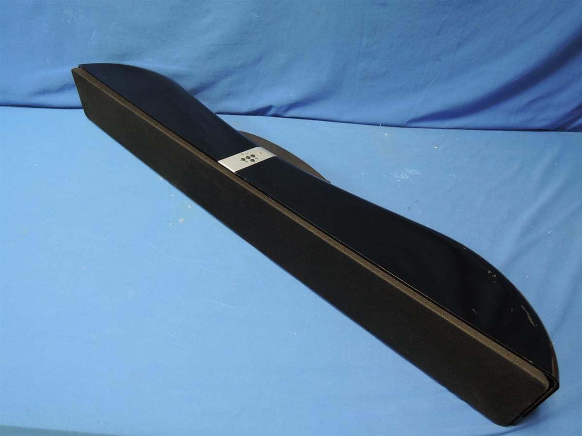
R48-SB218
Oct 29, 2015SoundBar Speaker
Equipment Class
NII - Unlicensed National Information Infrastructure TX
R48RKBTR2X
Aug 24, 2015Tabletop Stereo
Equipment Class
DSS - Part 15 Spread Spectrum Transmitter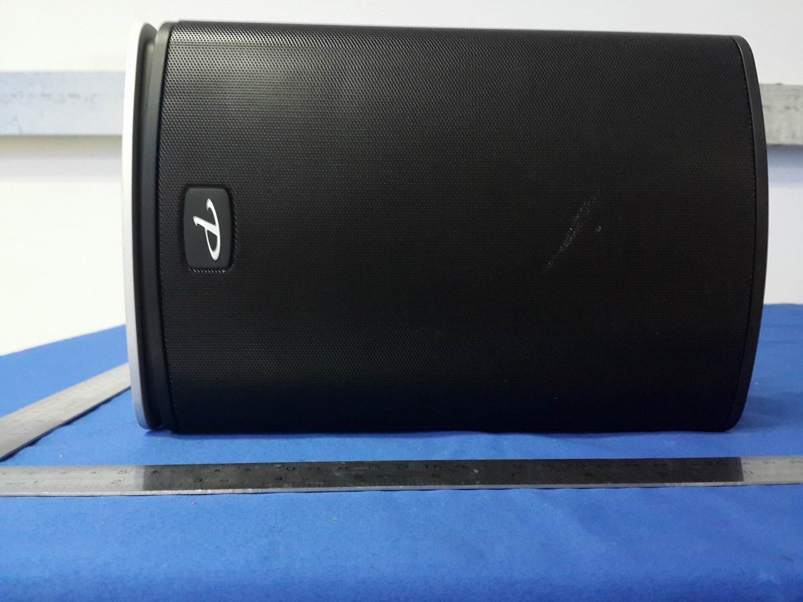
R48TT025
Aug 02, 2015active loudspeaker
Equipment Class
NII - Unlicensed National Information Infrastructure TX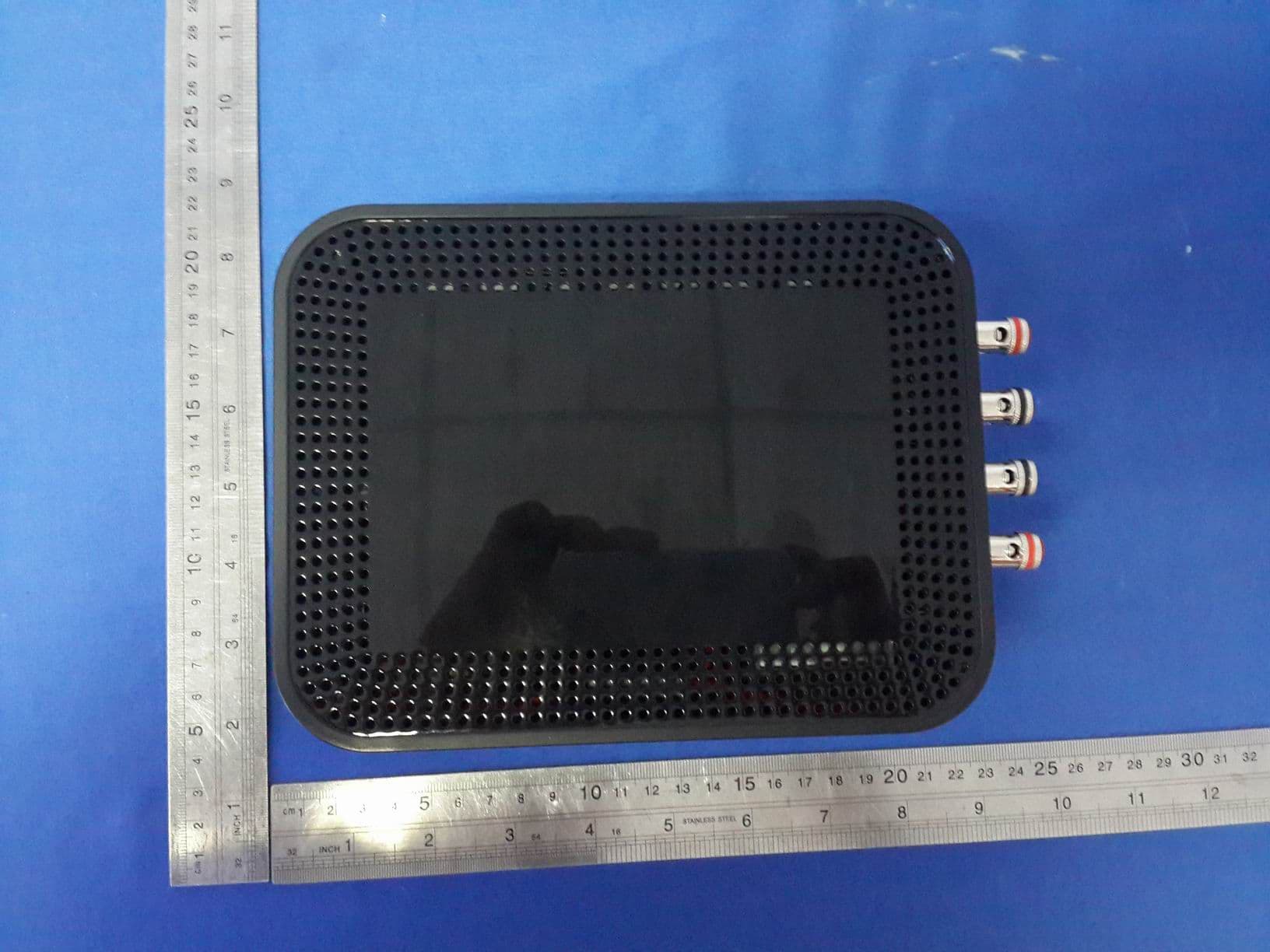
R48MP025
Jul 27, 2015active loudspeaker
Equipment Class
NII - Unlicensed National Information Infrastructure TX
R48RKBTMR1
Apr 08, 2015Active Bluetooth Speakers
Equipment Class
DSS - Part 15 Spread Spectrum Transmitter