R48CONTROL24GRXWireless Audio AMP Speaker System
Meiloon Industrial Co., Ltd.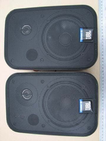
Click to zoom
Application Details
- Equipment Class
- DSS - Part 15 Spread Spectrum Transmitter
- Date of Grant
- Oct 23, 2006
- Application Purpose
- Original Equipment
- Date of Application
- Oct 23, 2006
- Equipment Note
- Wireless Audio AMP Speaker System
- Frequency Range
- 2403.00000000 - 2479.00000000
- Company
- Meiloon Industrial Co., Ltd.
- Country
- Taiwan
Documents & Files
Document Text
Text extracted from the exhibit documents filed with the FCC. Open a document above to read the original.
Users Manual
CONTROL 2.4G ON AIR ™ OWNER’S GUIDE ® T HANK YOU FOR CHOOSING JBL 2 For more than 60 years, JBL has been involved in every aspect of music and film recording and reproduction, from live performances t o the recordings you play in your home, car or office. We’re confident that the JBL system you have chosen will provide every note of enjoyment that you expected – and that when you think about purchasing additional audio equipment for your home, car or office, you will once again choose JBL. Please take a moment to register your product on our Web site at www.jbl.com. It enables us to keep you posted on our latest advance-ments, and helps us to better understand our customers and build products that meet their needs and expectations. The JBL OnAir™ Control 2.4G is an advanced wireless loudspeaker system t hat allows you to enjoy your favorite music in remote locations around your home or add surround speakers to your home theater system without running wires to the back of the room. To ensure trouble-free performance, please carefully read these instructions completely before connecting or using the system. Control 2.4G RIGHT CHANNEL SPEAKER TOLEFT SPEAKER +– Control 2.4G I D C ODE 1234 DC 20V S UBOUT LINE IN LEFT CHANNEL SPEAKER TORIGHTSPEAKER +– Control 2.4G RIGHT CHANNEL SPEAKER TOLEFT SPEAKER +– INPUT MUTE VOL INPUT R L I D CODE 1 234 U NPACKING THE SYSTEM Carefully unpack the system. If you suspect damage from transit, report it immediately to your dealer and/or delivery service. Keep the shipping carton and packing materials for future use. Open the package and verify the follow- ing contents: Included 1 x Transmitter Module 1 x Universal Power Supply for Transmitter 1 x 120V 2-prong AC power cord for Transmitter Power Supply 1 x 230V 2-prong AC power cord for Transmitter Power Supply 1 x Wallmount bracket for Transmitter with 2 x Pan head M3x4 machine screws for attaching wallmount bracket to transmitter 4 x small round self-adhesive feet – to be attached on Transmitter left side panel if Transmitter to be used vertically 1 x Active Speaker/Receiver (Left channel speaker) 1 x Universal Power Supply for Active Speaker/Receiver 1 x 120V 3-prong AC power cord for Active Speaker/Receiver Power Supply 1 x 230V 3-prong AC power cord for Active Speaker/Receiver Power Supply 2 x Wallmount rotatable brackets for active speaker (Includes bar wrench and back-up cords) 1 x Wallmount holder for Active Speaker/Receiver Universal Power Supply 1 x Passive Speaker (Right channel speaker) 2 x Wallmount rotatable brackets for active speaker (Includes bar wrench and back-up cords) 1 x Remote Control 1 x Interconnect cable (1m/3.3ft RCA – RCA) 1 x Interconnect cable (1m/3.3ft RCA – 1/8” mini plug) 10m/33ft. x Speaker Wire 1 x Owner’s Manual (Multilanguage) 1 x USA Warranty Sheet 3 CONNECTIONS +– 9 RIGHT CHANNEL SPEAKER TOLEFT SPEAKER ID CODE 1234 DC 20V SUB OUT LINE IN TORIGHT SPEAKER +– +– 4 5 68 9 7 LEFT CHANNEL SPEAKER RIGHT CHANNEL SPEAKER TOLEFT SPEAKER RL ID CODE 1234 A B CD INPUT INPUTMUTE VOL 1 2 0 3 NOTES: For the sake of simplicity, we have used the terms “receiver” and “A/V receiv- er” when describing the connections and operation, throughout the manual. We feel that the majority of customers purchasing this system will connect it to a receiver of some type. In the event that you are using an integrated ampli- fier, separate surround processor or computer sound card, the instructions would be applicable to your unit. The JBL OnAir Control 2.4G is designed for use worldwide and includes univer- sal power supplies for the Transmitter Module and Active Speaker. Please be sure to select and use the correct AC power cords (included) for your location. The JBL OnAir may be connected to your existing audio system in several ways. First, determine how you would like to use the JBL OnAir Control 2.4G, t hen follow the set-up instructions for that application. Application 1 Adding Surround Speakers to a home theater system. Continue reading the instructions for Application 1 below. Application 2 Adding speakers to remote locations around your home. Go directly to page xx. Application 1 Adding Surround Speakers to a home theater system. Determine if your receiver contains pre-amp outputs for rear-/surround-chan- nels, usually indicated by RCA type jacks on the back of the receiver labeLED as surround pre-out. (Please refer to your AV receiver’s owner’s manual to confirm whether it includes the pre-amp outputs.) If your receiver includes these outputs, follow the steps below. If not, connection is not recommended. NOTE: Make sure power is turned off on all components. Step 1 Connect the interconnect cable (included) to the left and right surround/rear pre-amp outputs on the back of your receiver and the input on the Transmitter Module Das shown in Figure 1. Step 2 Determine location of surround speakers. ( Place the active (left) speaker in the recommended location for the left sur- round speaker . Left Surround Channel R ight Surround Channel Left Front Channel Subwoofer Right Front C hannel C enter Channel Couch L Left Rear Channel Left Surround Channel Right Surround Channel Right Rear Channel Center Rear Channel Left Front Channel S ubwoofer Right Front Channel C enter Channel INPUT RL R L ID CODE 1234 R ECEIVER/PROCESSOR Surround Channel Pre-Amp Outputs 4 CONNECTIONS Step 3 Connect the speaker wire (included) to the push terminals on the Active Speaker 5and the push terminals on the rear of the Passive Speaker. See figure 4 . Step 4 Plug the Transmitter Module and Active Speaker into the wall outlet. Make sure the transmitter’s antenna Ais extended upwards. Step 5 If necessary, configure your A/V receiver to activate the pre-amp level outputs for the surround/rear channels. (Consult your receiver’s owner’s manual for specific instructions.) When connected properly, the top LED on the front of the Active Speaker should be green. The bottom LED should flash green until the Transmitter and Active Speak…
Text truncated - open the document above for the full version.
External Photos
ETS DR.GENZ TAIWAN PS CO., LTD. Registration number: W6M20608-7255-P-15-S FCC ID : R48CONTROL24GRX ETS Dr. Genz Taiwan PS Co., Ltd. External Photos ETS DR.GENZ TAIWAN PS CO., LTD. Registration number: W6M20608-7255-P-15-S FCC ID : R48CONTROL24GRX ETS Dr. Genz Taiwan PS Co., Ltd. ETS DR.GENZ TAIWAN PS CO., LTD. Registration number: W6M20608-7255-P-15-S FCC ID : R48CONTROL24GRX ETS Dr. Genz Taiwan PS Co., Ltd. Transmitter Box ETS DR.GENZ TAIWAN PS CO., LTD. Registration number: W6M20608-7255-P-15-S FCC ID : R48CONTROL24GRX ETS Dr. Genz Taiwan PS Co., Ltd. ETS DR.GENZ TAIWAN PS CO., LTD. Registration number: W6M20608-7255-P-15-S FCC ID : R48CONTROL24GRX ETS Dr. Genz Taiwan PS Co., Ltd. ETS DR.GENZ TAIWAN PS CO., LTD. Registration number: W6M20608-7255-P-15-S FCC ID : R48CONTROL24GRX ETS Dr. Genz Taiwan PS Co., Ltd. ETS DR.GENZ TAIWAN PS CO., LTD. Registration number: W6M20608-7255-P-15-S FCC ID : R48CONTROL24GRX ETS Dr. Genz Taiwan PS Co., Ltd. Speaker Amplifier ETS DR.GENZ TAIWAN PS CO., LTD. Registration number: W6M20608-7255-P-15-S FCC ID : R48CONTROL24GRX ETS Dr. Genz Taiwan PS Co., Ltd. ETS DR.GENZ TAIWAN PS CO., LTD. Registration number: W6M20608-7255-P-15-S FCC ID : R48CONTROL24GRX ETS Dr. Genz Taiwan PS Co., Ltd.
ID Label/Location Info
FCC ID: RX
RF Exposure Info
MPE Prediction FCC Rule: 15.247(b)(5) Systems operating under the provisions of this section shall be operated in a manner that ensures that the public is not exposed to radio frequency energy levels in excess of the Commission’s guidelines. See §1.1307(b)(1) of this Chapter. LIMITS FOR MAXIMUM PERMISSIBLE EXPOSURE (MPE) Frequency Range (MHz) Electric Field Strength (V/m) Magnetic Field Strength (A/m) Power Density (mW/cm2) Average time (minutes) (A)Limits For Occupational / Control Exposures 30-300 61.4 0.613 1.0 6 300-1500 ... ... F/300 6 1500-100,000 ... ... 5 6 (B)Limits For General Population / Uncontrolled Exposure 30-300 27.5 0.073 0.2 30 300-1500 ... ... F/1500 30 1500-100,000 ... ... 1.0 30 F = Frequency in MHz Prediction of MPE limit at a given distance Equation from page 18 of OET Bulletin 65, Edition 97-01 PG S = -------------- 4πR² where: S = power density P = power input to the antenna G = power gain of the antenna in the direction of interest relative to an isotropic radiator R = distance to the center of radiation of the antenna Maximum peak output power at antenna input terminal: 16.81 (dBm) Maximum peak output power at antenna input terminal: 49.97 (mW) Antenna gain(maximal): 1.53 (dBi) Prediction distance: 20 (cm) Prediction frequency: 2479 (MHz) MPE limit for uncontrolled exposure at prediction frequency: 1.0 (mW/cm²) Power density at prediction frequency: 0.01491 (mW/cm²) The manual instruct the user to install and operate the device in a minimum distance of 20 cm between antenna and the users body.
Test Report
ETS Dr.Genz Taiwan PS Co., LTD FCC Registration No.: 930600 Industry Canada filed test laboratory Reg. No. IC 5679 Accredited Testing Laboratory A2LA Cert.No.: 2300.01 PCTRB Accredited Type Certification Test House FCC TEST-REPORT FCC RULES PART 15 / SUBPART C FCC ID: R48CONTROL24GRX Test report no.: W6M20608-7255-P-15-S ETS DR.GENZ TAIWAN PS CO., LTD. 6F, NO. 58, LANE 188, RUEY-KUANG RD., NEIHU, TAIPEI 114, TAIWAN, R.O.C. PHONE 886-2-66068877 FAX 886-2-66068879 ETS DR.GENZ TAIWAN PS CO., LTD. . Registration number: W6M20608-7255-P-15-S FCC ID : R48CONTROL24GRX ETS Dr. Genz Taiwan PS Co., Ltd. Page 2 of 40 TABLE OF CONTENTS 1 GENERAL INFORMATION ...................................................................................................... 3 1.1 Notes .................................................................................................................................... 3 1.2 Testing laboratory ................................................................................................................ 4 1.2.1Location ....................................................................................................................... 4 1.2.2Details of accreditation status ..................................................................................... 4 1.3 Details of approval holder.................................................................................................... 4 1.4 Application details ............................................................................................................... 4 1.5 General information of Test item......................................................................................... 5 1.6 Test standards....................................................................................................................... 6 2 TECHNICAL TEST .................................................................................................................... 7 2.1 Summary of test results........................................................................................................ 7 2.2 Test environment.................................................................................................................. 7 2.3 Test Equipment List ............................................................................................................. 8 3 TEST RESULTS (ENCLOSURE) ............................................................................................ 12 3.1 Peak Output Power (transmitter)........................................................................................ 13 3.2 Equivalent isotropic radiated power .................................................................................. 15 3.2.1Transmitter................................................................................................................. 15 3.3 RF Exposure Compliance Requirements ........................................................................... 15 3.4 Out of Band Radiated Emissions ....................................................................................... 15 3.5 Transmitter Radiated Emissions in restricted Bands ......................................................... 16 3.6 Spurious emissions (tx) ...................................................................................................... 17 3.7 Carrier Frequency Separation ............................................................................................ 21 3.8 Number of Hopping Frequencies ....................................................................................... 22 3.8.1 Pseudorandom Frequency Hopping Sequence ......................................................... 22 3.8.2Coordination of hopping sequences to other transmitters......................................... 22 3.8.3System Receiver Hopping Capability......................................................................... 22 3.9 Time of Occupancy (Dwell Time) ................................................................................... 23 3.10 20dB Bandwidth .............................................................................................................. 24 3.10.1System Receiver Input Bandwidth.............................................................................. 24 3.11 Band-edge Compliance of RF Emissions ........................................................................ 25 3.12 Radiated Emissions from Receiver Section of Transceiver............................................. 26 3.13 Power Line Conducted Emission..................................................................................... 28 APPENDIX ........................................................................................................................................ 30 Appendix A .................................................................................................................................... 31 Appendix B .................................................................................................................................... 32 Appendix C .................................................................................................................................... 33 Appendix D .................................................................................................................................... 34 Appendix E .................................................................................................................................... 35 Appendix F..................................................................................................................................... 36 Appendix G .................................................................................................................................... 37 Appendix H ...................................................................................................................…
Text truncated - open the document above for the full version.
Test Setup Photos
ETS DR.GENZ TAIWAN PS CO., LTD. Registration number: W6M20608-7255-P-15-S FCC ID : R48CONTROL24GRX ETS Dr. Genz Taiwan PS Co., Ltd. Set Up Photos ETS DR.GENZ TAIWAN PS CO., LTD. Registration number: W6M20608-7255-P-15-S FCC ID : R48CONTROL24GRX ETS Dr. Genz Taiwan PS Co., Ltd. ETS DR.GENZ TAIWAN PS CO., LTD. Registration number: W6M20608-7255-P-15-S FCC ID : R48CONTROL24GRX ETS Dr. Genz Taiwan PS Co., Ltd. ETS DR.GENZ TAIWAN PS CO., LTD. Registration number: W6M20608-7255-P-15-S FCC ID : R48CONTROL24GRX ETS Dr. Genz Taiwan PS Co., Ltd.
Contact Information
Applicant
Peter Pan(Electric Engineer)
Technical Contact
ETS Dr. Genz Taiwan PS CO., LTD.Steven Chuang
[email protected]+886-2-6606-8877
6F., No. 58, Lane 188, Ruey Kuang Road, Neihu · Taipei · Taiwan
Non-Technical Contact
ETS Dr. Genz Taiwan PS CO., LTD.Chiney Chen
[email protected]+886-2-6606-8877
Test Firm
Worldwide Testing Services (Taiwan) Co. Ltd.Chang Tse-Ming
Technical Specifications
| # | Rule Parts | Frequency Range | Power Output |
|---|---|---|---|
| 1 | 15C | 2.40 GHz - 2.48 GHz | 47.97 mW |
Other Applications from Meiloon Industrial Co., Ltd.
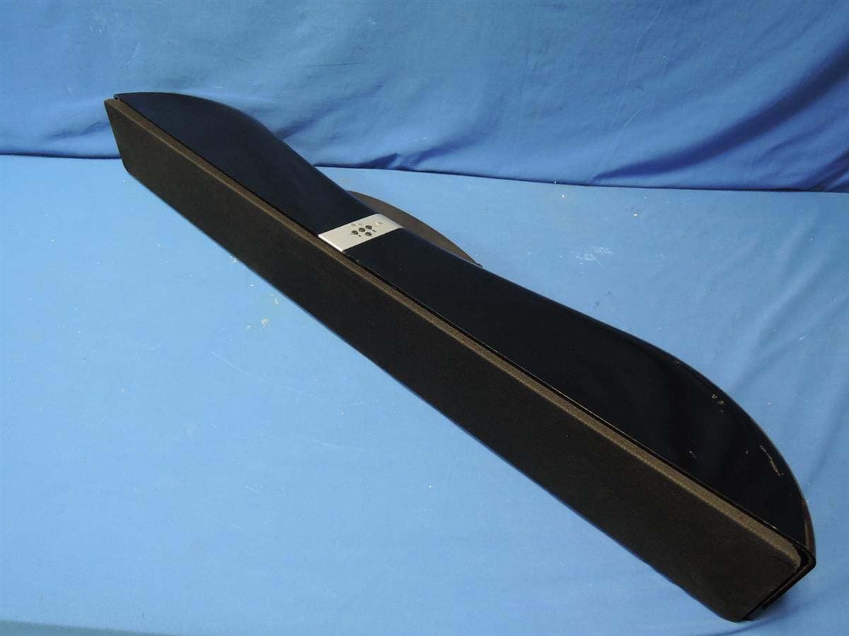
R48-SB218
Oct 29, 2015SoundBar Speaker
Equipment Class
NII - Unlicensed National Information Infrastructure TX
R48RKBTR2X
Aug 24, 2015Tabletop Stereo
Equipment Class
DSS - Part 15 Spread Spectrum Transmitter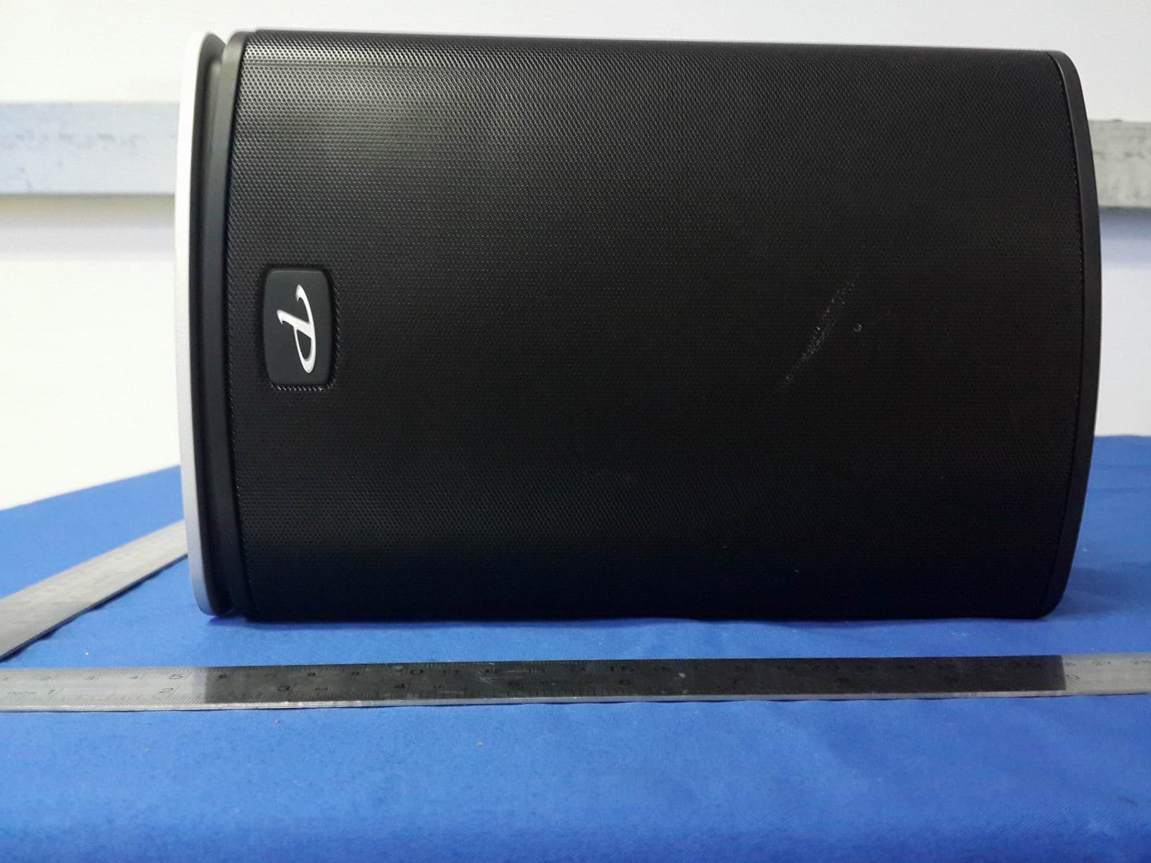
R48TT025
Aug 02, 2015active loudspeaker
Equipment Class
NII - Unlicensed National Information Infrastructure TX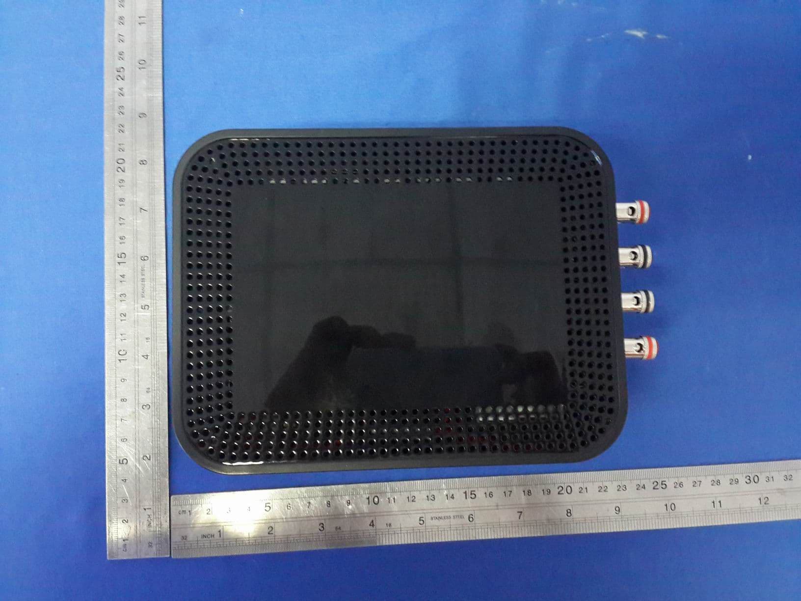
R48MP025
Jul 27, 2015active loudspeaker
Equipment Class
NII - Unlicensed National Information Infrastructure TX
R48RKBTMR1
Apr 08, 2015Active Bluetooth Speakers
Equipment Class
DSS - Part 15 Spread Spectrum Transmitter