R48KWTLSKorners Sub
Meiloon Industrial Co., Ltd.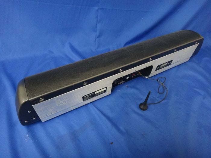
Click to zoom
Application Details
- Equipment Class
- DTS - Digital Transmission System
- Date of Grant
- Oct 22, 2013
- Application Purpose
- Original Equipment
- Date of Application
- Oct 21, 2013
- Equipment Note
- Korners Sub
- Frequency Range
- 5730.00000000 - 5822.50000000
- Company
- Meiloon Industrial Co., Ltd.
- Country
- Taiwan
Documents & Files
Document Text
Text extracted from the exhibit documents filed with the FCC. Open a document above to read the original.
Users Manual
Korners Sub English Designed and Engineered by K orners UUSER MAN AL 300-Watt Peak Wireless-Ready Subwoofer C ongratulations ! Thank you for selecting the Korners Sub by AudioXperts. The Korners Sub was designed specifically to complement our Korners collection of loudspeakers. Great care was taken to design a very compact but powerful subwoofer that has a multitude of positioning and hookup options. We are sure you will find it delivers a powerful bass experience, is built to the highest quality standards, and is designed to provide you with years of enjoyment. This user manual provides you with all the important information regarding the setup and use of your new powered subwoofer. Please keep this manual and all packaging materials stored in a safe place in case you need access to them at a later date. Key F eatures : • 300-watt Peak amplifier • Position in corner or against wall • RCA Line Level input • Optional Korners Konnect wireless transmitter for placement flexibility • Optional Korners Sub Connector for dual subwoofer configuration • Designed and engineered by AudioXperts Technical S pecications What’s included: For the latest product information, please visit: www.audioxperts.com/support Frequency Response (±3dB): 40Hz-300Hz Drivers: Six 4-1/2” (114mm) SSHO woofers Amplifier Power: 150 watts RMS, 300 watts PEAK Dimensions (HxWxD): 36 x 6-1/2 x 6-1/2” (914 x 165 x 165mm) Weight: 30 lbs. (13.6 Kg) Korners Sub 1- Subwoofer Stand 6- Mounting Screws for Subwoofer Stand 4- Floor Spikes 1- Power Cord 1- RF Antenna 1- User Manual Specifications are subject to change without notice. • Precision all digital signal flow and equalization • Variable parametric notch filter for room mode compensation Placement Options The Korners Sub is designed for both vertical and horizontal placement. For Vertical Placement, use the included floor stand to lift the bottom of the sub off the floor or carpet and place in corner for the best performance. The Korners Sub comes with 4 adjustable spikes that are to be used in conjunction with the floor stand. The spikes are meant for greater de-coupling and stability when the subwoofer is situated on a soft floor covering, like carpet. To attach the floor stand: 1. Align the holes on the stand with the Korners Sub. 2. Insert the 6 supplied mounting screws and tighten with a Philips-head screwdriver. For Horizontal Placement, place the subwoofer on the floor where it meets with a wall near your main speakers. For Both Positions, the sound is best when the subwoofer is within 15’ (4.5m) of the main speakers. The level of bass output will vary at different positions in a room. When placed near walls, its output is enhanced. Also, corner placement delivers maximum bass output. You can always adjust the level of the subwoofer from the sub’s built in volume control. vertical in a corner horizontal on floor IMPORTANT: Do not place your subwoofer where there is a chance of contact with furniture or curtains. 2 1 Control Panel POWER INPUT: AC120V/230V~50/60Hz Dip Gain Dip Freq 0 10 5 50 90 70 0 -8 -4 80 160 120 120V 230V Antenna VolumeCrossover In Out 0 180 1 2 3 4 Wireless Code Phase Single Double Wireless Line ON OFF T5AL/250V 1 6 5 4 3 2 10 9 8 13 12 11 1 7 6 5 4 3 2 10 9 8 13 12 11 Volume - Controls volume level. Dip Freq - Used for adjusting the frequency to correct Dip Gain - Used for adjusting the gain to correct Crossover - Adjusts the frequency of the low pass filter. In - Analog RCA cable input connection. Wireless/Line - Set to Line when using the RCA input. Set to Wireless when using the optional Korners Konnect Wireless Transmitter. 7 14 Out - Analog RCA cable output connection. Antenna - Connector for RF Antenna for wireless Wireless Code - Set to same channel as optional Korners Konnect wireless Transmitter. Voltage Switch - Set to 120V or 230V depending on your location. Single/Double - Set to Single for normal use. Set to Double when using two Korners Subs together. AC Input - Connect to wall power outlet. Power Switch - Main power on and off. 14 Phase Switch - 0 (normal) or 180 (inverted) Set this switch to deliver the fullest, most dynamic bass. The effect of phase is most audible with a repeating bass line. standing waves in the room. standing waves in the room. 15 15 Status Light - Solid Green when On, Solid Red when in Low Power State, LED blinks Green when wireless link is lost. operation. POWER INPUT: AC120V/230V~50/60Hz Dip Gain Dip Freq 0 10 5 50 90 70 0 -8 -4 80 160 120 120V 230V Antenna VolumeCrossover In Out 0 180 1 2 3 4 Wireless Code PhaseSingle Double Wireless Line ON OFF T5AL/250V Connections Note: Make sure the subwoofer is turned off before Preparation After the Korners Sub is properly placed you can now connect it to your system. The inputs for your Korners Sub are located on the back of the unit. Do not lay the unit on the grille side, as it may damage the grilles. Placing the unit on a padded surface can also prevent damage during setup. Line In Connect one end of the included RCA connection cable to the Subwoofer Out or LFE on the receiver or other audio component and the other end to the Line In RCA connection on the Korners Sub. AV Receiver Subwoofer Out or LFE POWER INPUT: AC120V/230V~50/60Hz Dip Gain Dip Freq 0 10 5 50 90 70 0 -8 -4 80 160 120 120V 230V Antenna VolumeCrossover In Out 0 180 1 2 3 4 Wireless Code Phase Single Double Wireless Line ON OFF T5AL/250V POWER INPUT: AC120V/230V~50/60Hz Dip Gain Dip Freq 0 10 5 50 90 70 0 -8 -4 80 160 120 120V 230V Antenna VolumeCrossover In Out 0 180 1 2 3 4 Wireless Code Phase Single Double Wireless Line ON OFF T5AL/250V Korners Sub 1 Korners Sub 2 Line Out The Line Out is used to send the input signal to another Korners Sub when connecting two subs together. To physically connect two Korners Subs together, you’ll need the optional Korners Sub Connector. Note: Line Out only works when RCA cable is connected to Line In Wireless (Optional Korners Konnect Wireless Transmitter) To enabl…
Text truncated - open the document above for the full version.
Users Manual
Panel de Control POWER INPUT: AC120V/230V~50/60Hz Dip Gain Dip Freq 0 10 5 50 90 70 0 -8 -4 80 160 120 120V 230V Antenna VolumeCrossover In Out 0 180 1 2 3 4 Wireless Code Phase Single Double Wireless Line ON OFF T5AL/250V 1 6 5 4 3 2 10 9 8 13 12 11 1 7 6 5 4 3 2 10 9 8 13 12 11 Volume - Controla el nivel de volumen. Dip Freq -Se utiliza para ajustar la frecuencia para Dip Gain - Se utiliza para ajustar la ganancia para Crossover - Ajusta la frecuencia del filtro de paso bajo. In - Cable analógico RCA de entrada de conexión. Wireless/Line - Se establece en la línea cuando se utiliza la RCA de entrada. Se establece en Wireless cuando se utiliza la opción Korners Konnect transmisor inalámbrico. 7 14 Out - Cable analógico RCA de salida de conexión. Antenna - Conector para antena RF para el Wireless Code - Se establece en el mismo canal como opcional Korners Konnect wireless Transmitter. Voltage Switch - Ajuste a 120 V o 230 V para su ubicación. Single/Double - Se establece en Single para el uso normal. Se establece en Double cuando utilizando dos Korners Subs juntos. Entrada AC - Conecte a la toma de corriente de la pared. Power - La alimentación principal encendido y apagado. 14 Phase - 0 (normal) o 180 (invertida) Sitúe este interruptor en Deiver más lleno, más dinámico de graves. el efecto fase de es más audible con una línea de bajo repetitiva. 15 15 Status Light - Verde fijo cuando Red On, sólido cuando está en estado de bajo consumo, LED parpadea en verde cuando la conexión inalámbrica está perdido. corregir las ondas estacionarias en la habitación. corregir las ondas estacionarias en la habitación. funcionamiento inalámbrico POWER INPUT: AC120V/230V~50/60Hz Dip Gain Dip Freq 0 10 5 50 90 70 0 -8 -4 80 160 120 120V 230V Antenna VolumeCrossover In Out 0 180 1 2 3 4 Wireless Code PhaseSingle Double Wireless Line ON OFF T5AL/250V Conexiones Nota: Asegúrese de que el subwoofer está apagado antes de realizar las conexiones. Preparación Después de la Korners Sub está correctamente colocado ahora puede conectarse a su sistema. Las entradas para su Korners Sub están situados en la parte posterior de la unidad. No coloque la unidad en el lado de la parrilla, ya que puede dañar el rejillas. Coloque la unidad sobre una superficie acolchada también puede prevenir el daño durante la instalación. En línea - Conecte un extremo del cable de conexión RCA incluido a la Salida de subwoofer o LFE del receptor o componente de audio y el otro extremo a la entrada de línea de conexión RCA en el Korners Sub. Receptor Subwoofer Out or LFE POWER INPUT: AC120V/230V~50/60Hz Dip Gain Dip Freq 0 10 5 50 90 70 0 -8 -4 80 160 120 120V 230V Antenna VolumeCrossover In Out 0 180 1 2 3 4 Wireless Code Phase Single Double Wireless Line ON OFF T5AL/250V POWER INPUT: AC120V/230V~50/60Hz Dip Gain Dip Freq 0 10 5 50 90 70 0 -8 -4 80 160 120 120V 230V Antenna VolumeCrossover In Out 0 180 1 2 3 4 Wireless Code Phase Single Double Wireless Line ON OFF T5AL/250V Korners Sub 1 Korners Sub 2 Salida de línea - La salida de línea se utiliza para enviar la señal de entrada a otro Korners Sub Al conectar dos subwoofers juntos. para físicamente conectar dos Suplentes Korners juntos, tendrá la opción Korners Sub Connector. Nota: La línea de salida sólo funciona cuando está conectado el cable RCA para entrada de línea y una señal presente. Opcional Korners Konnect Cable de alimentación LRLFE DC 5V 4 3 2 1 Input L R Subwoofer Wireless CODE 1 2 3 4 Wireless CODE 1 2 3 4 Korners Konnect Korners Sub = Receptor Wireless (Opcional Korners Konnect Transmisor Inalámbrico) Para activar el subwoofer Korners para recibir audio de forma inalámbrica,usted tendrá que comprar el Wireless Korners Konnect opcional Transmisor de un distribuidor autorizado AudioXperts. 1. Conecte la fuente de alimentación a la Korners Konnect y luego conecte el otro extremo a una toma de corriente de la pared. 2. A continuación, conecte un extremo del cable RCA a la En la línea de conexión de la Korners Konnect y el otro extremo a la Subwoofer o LFE salida de su receptor o componente de audio. 3. Una vez que el Konnect Korners es toda la configuración, conecte la antena inalámbrica al panel de conexión Korners Sub. 4. A continuación coloque el interruptor Wireless / Line con "inalámbrico" en la Korners Sub 5. Asegúrese de que el interruptor de código inalámbrico está configurado en el mismo canal tanto en el número Korners Sub y KornersKonnect. ADVERTENCIA: No conecte la fuente de audio al mismo subwoofer y Korners Konnect transmisor inalámbrico al mismo tiempo. Conexión de la alimentación Conecte el cable de alimentación a la entrada de alimentación. Asegúrese de que la potencia selector de voltaje esté en la posición correcta para el voltaje local alimentación de red. A continuación, conecte el cable de alimentación directamente a una toma de corriente. Algunos receptores AV y componentes proporcionar energía auxiliar puntos de venta, pero por favor evite el uso de ellos. Puede que no sean capaces de proporcionar el nivel de corriente requerida por el Korners Sub. POWER IN AC120V/23H z Dip Gain Dip Freq 0 10 5 50 90 70 0 -8 -4 80 160 120 120V 230V Antenna VolumeCrossover In Out 0 180 1 2 3 4 Wireless Code PhaseSingle Double Wireless Line ON OFF Uso del panel de control Volume Utilice el control de volumen para ajustar el nivel de salida que usted prefiera. Dip Freq y Dip Gain La mayoría de los ajustes de la habitación y las instalaciones subwoofer resultado en un gran pico en la respuesta de frecuencia del sistema debido a las ondas estacionarias en la habitación. Se ha incluido un mecanismo de ajuste simple ayudar a aliviar esta condición. Si después de la instalación inicial y la escucha, usted siente que hay una prominencia de la energía de baja frecuencia que no puede ajustarse para el uso de los controles de nivel o polaridad, entonces no es probable que un pico para corregir. Los picos en una habitación caen generalmente entre 50 y 90 Hz. Para empezar, establezca …
Text truncated - open the document above for the full version.
Users Manual
kan uppstå på grund av farlig spänning. användaren bör läsa alla säkerhetsmeddelanden som 1. Läs dessa instruktioner. 2. Behåll dessa instruktioner. 3. Respektera alla varningar. 4. Följ alla instruktioner. 5. Använd inte apparaten i närheten av vatten. 6. Rengör endast med en torr torkduk. 7. Blockera inte några ventilationsöppningar. Installera i enlighet med tillverkarens instruktioner. 8. Installera inte i närheten av värmekällor som element, värmespjäll, spisar eller andra apparater (inklusive förstärkare) som alstrar värme. 9. Försumma inte säkerhetsfunktionen hos polariserade eller jordade stickkontakter. En polariserad stickkontakt har två blad, det ena bredare än det andra. En stickkontakt av jordad typ har två blad och en tredje jordpinne. Det breda bladet och den tredje pinnen tillhandahålls för din säkerhet. Om den medföljande stickkontakten inte passar i ditt uttag, rådfråga en elektriker för byte av uttaget. 10. Skydda strömkabeln så att man inte snavar över den eller att den skadas, i synnerhet vid kontakter, fasta honkontakter och där kabeln lämnar apparaten. VIKTIG SÄKERHETSINFORMATION Denna symbol på utrustningen visar dubbelisolering. Varning! För att reducera risken för eldsvåda eller elektriska stötar, utsätt inte denna apparat för regn eller fukt. 11. av tillverkaren. 12. Koppla apparaten under åskväder eller när den inte ska används under en längre tidsperiod.ur 13. krävs när apparaten har skadats på något sätt, till exempel om strömkabeln eller kontakten har skadats, vätska har spillts ut eller föremål har fallit ned på apparaten, om apparaten har utsatts för regn eller fukt, inte fungerar normalt eller har tappats. 14. Håll ett minsta avstånd på runt apparatens framsida, baksida och sidor, för att möjliggöra tillräcklig ventilation. Ventilationen ska inte förhindras genom att täcka över ventilationsöppningar eller placering av föremål som tidningar, dukar eller gardiner runt eller på apparaten 50 mm2 in. 15. placeras på apparaten. 16. Apparaten bör inte utsättas för dropp eller stänk. Inga föremål fyllda med vätskor, som exempelvis blomvaser, bör placeras på apparaten. 17. Antingen strömanslutningen på baksidan av apparaten eller strömkontakten på väggen måste förbli åtkomliga, för att man ska kunna koppla bort strömmen från apparaten. 18. För att fullständigt koppla bort apparaten från elnätet, koppla bort strömkontakten från strömuttaget. I Frankrike får denna utrustning enbart användas inomhus. I Italien får denna utrustning enbart användas i ägarens lokaler. I LU är denna utrustning enbart avsedd för privat bruk. Får inte användas inom en radie på 20 km från Ny-Ålesund centrum i NO. Härmed AudioXperts, Inc. 505 Paradise Rd. Ste. 397, Swampscott, MA 01907 USA att denna Korners Sub är i överensstämmelse med de väsentliga egenskapskrav och övriga relevanta bestämmelser som framgår av direktiv 1999/5/EG. En kopia av försäkran om överensstämmelse (DOC) kan erhållas från: Mark Nazar AudioXperts,Inc. 505 Paradise Rd. Ste. 397 Swampscott, MA 01907 USA AT CZ FI IS LT PT SE FR BE DK DE IE MT SK CH IT EE GR LV NL SI TR LU CY HU PL ES GB NO RLAN - Radio Local Area Network Equipment (lokal radionätverksutrustning) Denna digitala klass B-apparat uppfyller kanadensisk ICES-003 Cet appareil numérique de classe B est conforme á la norme NMB-003 du Canada. OBS! Utrustningen har testats och överrensstämmer med begränsningarna för digitala apparater tillhörande Klass B, i enlighet med del 15 av FCC-reglerna. Dessa begränsningar är utvecklade för att tillhandahålla rimligt skydd mot skadlig inverkan i hushållet. Denna utrustning generar, använder och kan avge radiofrekvensen- ergi och kan, om den inte installeras och används i enlighet med instruktionerna, orsaka skadliga störningar på radiokommunika- negativa störningar för radio- eller TV-mottagning, vilket kan bekräftas genom att stänga av och sätta på utrustningen, uppmanas användaren att försöka korrigera störningen med hjälp av en eller • Ändra antennens riktning eller placering. • Öka avståndet mellan utrustningen och mottagaren. • Anslut utrustningen till ett uttag som ligger på en annan ledning än den som receivern är ansluten till. . Försiktighet: Försiktighet: Ej auktoriserade ändringar eller auktoritet att använda utrustningen. Användare i USA: Kanadensiska användare: Europeiska användare:
External Photos
Report No.: 136006R-RFUSP42V01 Page : 1 of 3 Attachment 2 : EUT Detailed Photographs (1) EUT Photo (2) EUT Photo Report No.: 136006R-RFUSP42V01 Page : 2 of 3 (3) EUT Photo (4) EUT Photo Report No.: 136006R-RFUSP42V01 Page : 3 of 3 (5) EUT Photo
ID Label/Location Info
Meiloon Industrial Co., Ltd. FCC ID.: R48KWTLS NO. 77, LANE 1775, CHUEN-RYH ROAD, TAOYUAN CITY, TAIWAN Tel : 88633261611 The FCC ID Label will be placed on the equipment as shown in the photograph below.
ID Label/Location Info
Meiloon Industrial Co., Ltd. FCC ID.: R48KWTLS NO. 77, LANE 1775, CHUEN-RYH ROAD, TAOYUAN CITY, TAIWAN Tel : 88633261611 FCC ID Label
Internal Photos
Report No.: 136006R-RFUSP42V01 Page : 1 of 8 Attachment 2 : EUT Detailed Photographs (6) EUT Photo (7) EUT Photo Report No.: 136006R-RFUSP42V01 Page : 2 of 8 (8) EUT Photo (9) EUT Photo Report No.: 136006R-RFUSP42V01 Page : 3 of 8 (10) EUT Photo (11) EUT Photo Report No.: 136006R-RFUSP42V01 Page : 4 of 8 (12) EUT Photo (13) EUT Photo Report No.: 136006R-RFUSP42V01 Page : 5 of 8 (14) EUT Photo (15) EUT Photo Report No.: 136006R-RFUSP42V01 Page : 6 of 8 (16) EUT Photo (17) EUT Photo Report No.: 136006R-RFUSP42V01 Page : 7 of 8 (18) EUT Photo (19) EUT Photo Report No.: 136006R-RFUSP42V01 Page : 8 of 8 (20) EUT Photo (21) EUT Photo
RF Exposure Info
Report No. 136006R-RFUSP42V01 Page: 1 of 3 RF Exposure Evaluation declaration Product Name Korners Sub Model No. Korners Sub FCC ID R48KWTLS Applicant Meiloon Industrial Co., Ltd. Address NO. 77, LANE 1775, CHUEN-RYH ROAD, TAOYUAN CITY, TAIWAN Date of Receipt May 27, 2013 Date of Declaration Aug. 29, 2013 Report No. 136006R-RFUSP42V01 The declaration results relate only to the samples calculated. The declaration shall not be reproduced except in full without the written approval of QuieTek Corporation. This report must not be used to claim product endorsement by TAF any agency of the U.S. Government Report No. 136006R-RFUSP42V01 Page: 2 of 3 1. RF Exposure Evaluation 1.1. Limits According to FCC 1.1310: The criteria listed in the following table shall be used to evaluate the environment impact of human exposure to radio frequency (RF) radiation as specified in 1.1307(b) LIMITS FOR MAXIMUM PERMISSIBLE EXPOSURE (MPE) Frequency Range (MHz) Electric Field Strength (V/m) Magnetic Field Strength (A/m) Power Density (mW/cm 2 ) Average Time (Minutes) (A) Limits for Occupational/ Control Exposures 300-1500 -- -- F/300 6 1500-100,000 -- -- 5 6 (B) Limits for General Population/ Uncontrolled Exposures 300-1500 -- -- F/1500 6 1500-100,000 -- -- 1 30 F= Frequency in MHz Friis Formula Friis transmission formula: Pd = (Pout*G)/(4*pi*r 2 ) Where Pd = power density in mW/cm 2 Pout = output power to antenna in mW G = gain of antenna in linear scale Pi = 3.1416 R = distance between observation point and center of the radiator in cm Pd id the limit of MPE, 1 mW/cm 2 . If we know the maximum gain of the antenna and the total power input to the antenna, through the calculation, we will know the distance r where the MPE limit is reached. 1.2. Test Procedure Software provided by client enabled the EUT to transmit and receive data at lowest, middle and highest channel individually. The temperature and related humidity: 18°Cand 78% RH. Report No. 136006R-RFUSP42V01 Page: 3 of 3 1.3. Test Result of RF Exposure Evaluation Product : Korners Sub Test Item : RF Exposure Evaluation Test Site : No.3 OATS Operation Frequency 5730~5822.5MHz Maximum Conducted output power 10.65dBm Antenna gain 3.8dBi Output Power Into Antenna & RF Exposure Evaluation Distance: Output Power to Antenna (mW) Power Density at R = 20 cm (mW/cm2) 11.6145 0.005543 Power density in column 4 is much lower than the limit (1 mW/cm 2 ).
Test Report
Report No. 136006R-RFUSP42V01 Page: 1 of 43 FCC Test Report Product Name Korners Sub Model No Korners Sub FCC ID. R48KWTLS Applicant Meiloon Industrial Co., Ltd. Address NO. 77, LANE 1775, CHUEN-RYH ROAD, TAOYUAN CITY, TAIWAN Date of Receipt May 27, 2013 Issue Date Aug. 29, 2013 Report No. 136006R-RFUSP42V01 Report Version V1.0 The test results relate only to the samples tested. The test report shall not be reproduced except in full without the written approval of QuieTek Corporation. This report must not be used to claim product endorsement by TAF or any agency of the U.S. Government. Report No. 136006R-RFUSP42V01 Page: 2 of 43 Test Report Certification Issue Date: Aug. 29, 2013 Report No.: 136006R-RFUSP42V01 Product Name Korners Sub Applicant Meiloon Industrial Co., Ltd. Address NO. 77, LANE 1775, CHUEN-RYH ROAD, TAOYUAN CITY, TAIWAN Manufacturer AudioXperts Model No. Korners Sub EUT Rated Voltage AC 100-240V, 50/60Hz EUT Test Voltage AC 120V/60Hz Trade Name Applicable Standard FCC CFR Title 47 Part 15 Subpart C: 2012 ANSI C63.4: 2003, ANSI C63.10: 2009, KDB 558074 Test Result Complied The test results relate only to the samples tested. The test report shall not be reproduced except in full without the written approval of QuieTek Corporation. This report must not be used to claim product endorsement by TAF or any agency of the U.S. Government Documented By : ( Senior Adm. Specialist / Joanne Lin ) Tested By : (Assistant Engineer / Nowal Kuo ) Approved By : ( Manager / Vincent Lin) Report No. 136006R-RFUSP42V01 Page: 3 of 43 TABLE OF CONTENTS Description Page 1. GENERAL INFORMATION .....................................................................................................5 1.1. EUT Description............................................................................................................................5 1.2. Operational Description ................................................................................................................6 1.3. Tested System Details....................................................................................................................8 1.4. Configuration of Tested System ....................................................................................................8 1.5. EUT Exercise Software .................................................................................................................8 1.6. Test Facility ...................................................................................................................................9 2. Conducted Emission..................................................................................................................10 2.1. Test Equipment............................................................................................................................10 2.2. Test Setup ....................................................................................................................................10 2.3. Limits ..........................................................................................................................................11 2.4. Test Procedure .............................................................................................................................11 2.5. Uncertainty ..................................................................................................................................11 2.6. Test Result of Conducted Emission.............................................................................................12 3. Peak Power Output ...................................................................................................................14 3.1. Test Equipment............................................................................................................................14 3.2. Test Setup ....................................................................................................................................14 3.3. Limits ..........................................................................................................................................14 3.4. Test Procedure .............................................................................................................................14 3.5. Uncertainty ..................................................................................................................................14 3.6. Test Result of Peak Power Output...............................................................................................15 4. Radiated Emission .....................................................................................................................16 4.1. Test Equipment............................................................................................................................16 4.2. Test Setup ....................................................................................................................................17 4.3. Limits ..........................................................................................................................................18 4.4. Test Procedure .............................................................................................................................19 4.5. Uncertainty ..................................................................................................................................19 4.6. Test Result of Radiated Emission................................................................................................20 5. RF antenna conducted test........................................................................................................24 5.1. Test Equipment............................................................................................................................24 5.2. Test Setup ..........................................................…
Text truncated - open the document above for the full version.
Test Setup Photos
Report No.: 136006R-RFUSP42V01 Page : 1 of 4 Attachment 1: EUT Test Setup Photographs Front View of Conducted Test Back View of Conducted Test Report No.: 136006R-RFUSP42V01 Page : 2 of 4 Front View of Radiated Test Back View of Radiated Test Report No.: 136006R-RFUSP42V01 Page : 3 of 4 Front View of Radiated Test (Horn) Back View of Radiated Test (Horn) Report No.: 136006R-RFUSP42V01 Page : 4 of 4 Front View of Radiated Test (Horn) Back View of Radiated Test (Horn)
Contact Information
Applicant
Peter Pan(Electric Engineer)
Technical Contact
QuieTek CorporationSabina Chen
[email protected]886-2-8601-3788
No. 5-22, Rueishu Keng, Linkou Dist., · New Taipei · Taiwan
Test Firm
DEKRA Testing and Certification Co., Ltd.Sky Hsu
Technical Specifications
| # | Rule Parts | Frequency Range | Power Output |
|---|---|---|---|
| 1 | 15C | 5.73 GHz - 5.82 GHz | 11.60 mW |
Other Applications from Meiloon Industrial Co., Ltd.
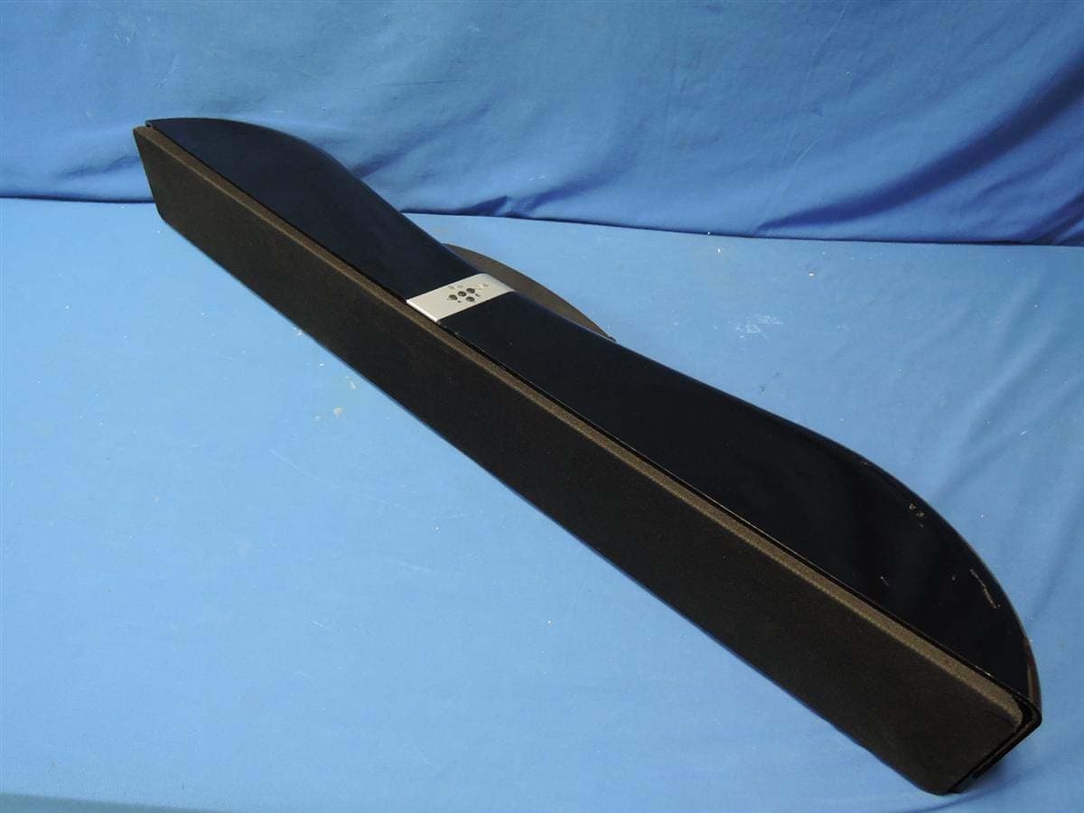
R48-SB218
Oct 29, 2015SoundBar Speaker
Equipment Class
NII - Unlicensed National Information Infrastructure TX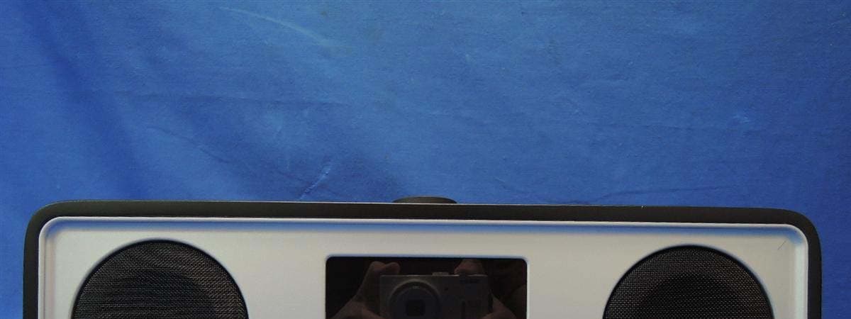
R48RKBTR2X
Aug 24, 2015Tabletop Stereo
Equipment Class
DSS - Part 15 Spread Spectrum Transmitter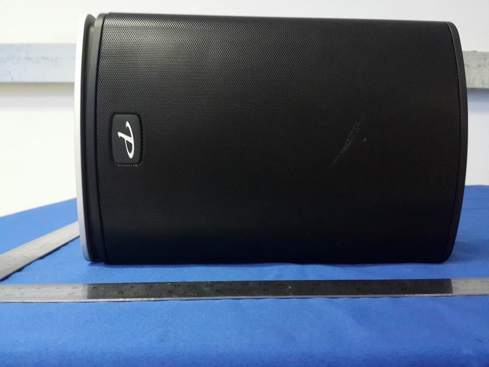
R48TT025
Aug 02, 2015active loudspeaker
Equipment Class
NII - Unlicensed National Information Infrastructure TX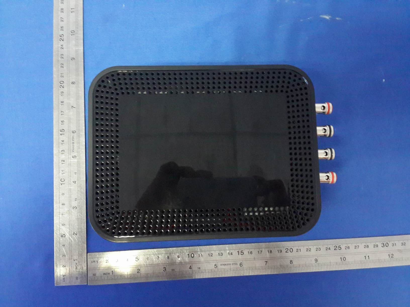
R48MP025
Jul 27, 2015active loudspeaker
Equipment Class
NII - Unlicensed National Information Infrastructure TX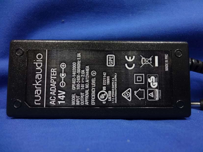
R48RKBTMR1
Apr 08, 2015Active Bluetooth Speakers
Equipment Class
DSS - Part 15 Spread Spectrum Transmitter