R4T-WISARF01Communication Module
ABB Stotz-Kontakt GmbH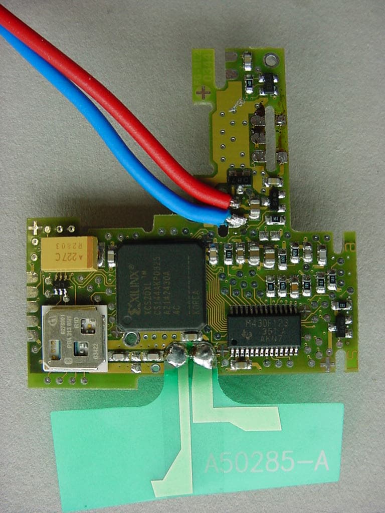
Click to zoom
Application Details
- Equipment Class
- DSS - Part 15 Spread Spectrum Transmitter
- Date of Grant
- Jul 27, 2006
- Application Purpose
- Original Equipment
- Date of Application
- Jul 27, 2006
- Equipment Note
- Communication Module
- Frequency Range
- 2402.00000000 - 2478.00000000
- Company
- ABB Stotz-Kontakt GmbH
- Country
- Germany
Documents & Files
Document Text
Text extracted from the exhibit documents filed with the FCC. Open a document above to read the original.
Users Manual
ABB STOTZ-KONTAKT GmbH, Eppelheimer Straße 82, 69123 Heidelberg, http://www.abb.de/stotz-kontakt Von/From Name Telefon/Phone Fax Seite/Page STO/CA Alexander Bock +49 6221/701- 1287 +49 6221/701- 1344 1/1 Datum/Date 2006-07-19 Implementation instruction for Wireless communication module WISARF01 The wireless communication module WISARF01 is only be allowed to be implemented into other devices under license and instruction of ABB Stotz-Kontakt GmbH. General: This device complies with Part 15 of the FCC Rules and with RSS-210 of Industry Canada. Operation is subject to the following two conditions: (1) this device my not cause harmful interference, and (2) this device must accept any interference received, including interference that may cause undesired operation. Warning: Changes or modifications made to this equipment not expressly approved by ABB Stotz-Kontakt GmbH may void the FCC authorization to operate this equipment. This equipment has been tested and found to comply with the limits for a Class B digital device, pursuant to Part 15 of the FCC Rules. These limits are designed to provide reasonable protection against harmful interference in a residential installation. This equipment generates, uses and can radiate radio frequency energy and, if not installed and used in accordance with the instructions, may cause harmful interference to radio communications. However, there is no guarantee that interference will not occur in a particular installation. If this equipment does cause harmful interference to radio or television reception, which can be determined by turning the equipment off and on, the user is encouraged to try to correct the interference by one or more of the following measures: • Reorient or relocate the receiving antenna. • Increase the separation between the equipment and receiver. • Connect the equipment into an outlet on a circuit different from that to which the receiver is connected. • Consult the dealer or an experienced radio/TV technician for help.
Cover Letter(s)
CONFIDENTIALITY REQUEST Federal Communication Commission Equipment Authorization Division, Application Processing Branch 7435 Oakland Mills Road Columbia, MD 21048 June 23, 2006 TO WHOM IT MAY CONCERN Pursuant to Paragraphs §0.457 and 0.459 of the Commission’s Rules (47 C.F.R.) and Section §552(b)(4) of the Freedom of Information Act, ABB Stotz-Kontakt GmbH requests confidentiality for the following products: FCC ID Number Product Title/Model R4T-WISARF01 WISARF01 For the product stated above, we request that the following information be held confidential: 1. Circuit diagrams, BOM, and PCBs submitted as Equipment Authorization Electronic Filing attachment: "schematics”. 2. Block diagram submitted as Equipment Authorization Electronic Filing attachment: “blockdiagram”. 3. Operational description submitted as Equipment Authorization Electronic Filing attachment: “operational description” The above exhibits contain ABB Stotz-Kontakt GmbH trade secrets and proprietary information that could be of benefit to our competitors regarding the design of our mobile handset. This material is not customarily available to the general public and we request that it be withheld from public inspection. If you have any questions, please feel free to contact me at the address shown below. Sincerely, Name: Alexander Bock Company: ABB Stotz-Kontakt GmbH Address: Eppelheimer Strasse 82; 69123 Heidelberg; Germany Phone: +49 6221 / 701 1287 Email: [email protected]
Cover Letter(s)
1. The modular transmitter must have its own RF shielding. This is intended to ensure that the module does not have to rely upon the shielding provided by the device into which it is installed in order for all modular transmitter emissions to comply with Part 15 limits. It is also intended to prevent coupling between the RF circuitry of the module and any wires or circuits in the device into which the module is installed. Such coupling may result in noncompliant operation. The transmitter used in the system is a standard Bluetooth radio (PBA 313 05) with equipped with a shielding box on the upper side. Shielding on the PCB-side is assured by a GND plane in one of the inner layers of the PCB. 2. The modular transmitter must have buffered modulation/data inputs (if such inputs are provided) to ensure that the module will comply with Part 15 requirements under conditions of excessive data rates or over-modulation. The radio frequency characteristics of the module are identical to those of Bluetooth. A Gaussian-shaped, binary FSK modulation is applied with a BT product of 0.5. The modulation index is between 0.28 and 0.35, corresponding to a frequency deviation of 140 kHz to 175 kHz. This is a characteristic of the used transmitter which can not be influenced. The module is made for industrial applications with specified maximum data rate. There are two interfaces implemented. One is a 1-bit logical input and the other on is a SPI-interface able to handle 32bit information in in- and outputdirection. If the trigger rate is to high the module is able to store one event until the last event is transmitted. If there would be a second event during this time the module would transmit an error message. 3. The modular transmitter must have its own power supply regulation. This is intended to ensure that the module will comply with Part 15 requirements regardless of the design of the power supplying circuitry in the device into which the module is installed. The 10V is connected to a DC/DC converter to create a regulated 3V (nominal) supply voltage for the module. The 10V is monitored at the module. The 3V regulator on the module will be turned on at a voltage of >7,6V and turned off at a voltage of <3,6V. The supply voltage for the transmitter its own is generated with a low-dropout regulator out of the regulated 3V supply and is slightly lower than the 3V. In practice it’s also possible to feed the system with a regulated 3.1V supply where also the supply for the transmitter will be generated by the low-dropout regulator. 4. The modular transmitter must comply with the antenna requirements of Section 15.203 and 15.204(c). The antenna must either be permanently attached or employ a “unique” antenna coupler (at all connections between the module and the antenna, including the cable). Any antenna used with the module must be approved with the module, either at the time of initial authorization or through a Class II permissive change. The “professional installation” provision of Section 15.203 may not be applied to modules. The connection pads for the antenna are especially designed for a customized antenna made for this module. There are no additional antenna connectors mounted. The antenna is part of the module. 5. The modular transmitter must be tested in a stand-alone configuration, i.e., the module must not be inside another device during testing. This is intended to demonstrate that the module is capable of complying with Part 15 emission limits regardless of the device into which it is eventually installed. Unless the transmitter module will be battery powered, it must comply with the AC line conducted requirements found in Section 15.207. AC or DC power lines and data input/output lines connected to the module must not contain ferrites, unless they will be marketed with the module (see Section 15.27(a)). The length of these lines shall be length typical of actual use or, if that length is unknown, at least 10 centimeters to insure that there is no coupling between the case of the module and supporting equipment. Any accessories, peripherals, or support equipment connected to the module during testing shall be unmodified or commercially available (see Section 15.31(i)). Tests have been done at CETECOM test laboratories in Saarbrücken, Germany. 6. The modular transmitter must be labeled with its own FCC ID number, and, if the FCC ID is not visible when the module is installed inside another device, then the outside of the device into which the module is installed must also display a label referring to the enclosed module. This exterior label can use wording such as the following: “Contains Transmitter Module FCC ID: XYZMODEL1” or “Contains FCC ID: XYZMODEL1.” Any similar wording that expresses the same meaning may be used. The Grantee may either provide such a label, an example of which must be included in the application for equipment authorization, or, must provide adequate instructions along with the module which explain this requirement. In the latter case, a copy of these instructions must be included in the application for equipment authorization confirmed by picture 7. The modular transmitter must comply with any specific rule or operating requirements applicable to the transmitter and the manufacturer must provide adequate instructions along with the module to explain any such requirements. A copy of these instructions must be included in the application for equipment authorization. For example, there are very strict operational and timing requirements that must be met before a transmitter is authorized for operation under Section 15.231. For instance, data transmission is prohibited, except for operation under Section 15.231(e), in which case there are separate field strength level and timing requirements. Compliance with these requirements must be assured. The RF behaviour of the module is defined by the used standard BT Radio. This can’t be influenced (shielding effects neglected) fro…
Text truncated - open the document above for the full version.
External Photos
CETECOM ICT Services GmbH Untertürkheimer Str. 6-10, 66117 Saarbruecken Phone: +49 (0) 681 598-0 Fax: -9075 RSC-Laboratory Phone: +49 (0) 681 598-0 Fax: -9075 Test report no.: 4-1982-02-02/06 Date: 2006-04-04 Page 47 of 48 Photo 3: CETECOM ICT Services GmbH Untertürkheimer Str. 6-10, 66117 Saarbruecken Phone: +49 (0) 681 598-0 Fax: -9075 RSC-Laboratory Phone: +49 (0) 681 598-0 Fax: -9075 Test report no.: 4-1982-02-02/06 Date: 2006-04-04 Page 48 of 48 Photo 4:
Internal Photos
CETECOM ICT Services GmbH Untertürkheimer Str. 6-10, 66117 Saarbruecken Phone: +49 (0) 681 598-0 Fax: -9075 RSC-Laboratory Phone: +49 (0) 681 598-0 Fax: -9075 Test report no.: 4-1982-02-02/06 Date: 2006-04-04 Page 47 of 48 Photo 3: CETECOM ICT Services GmbH Untertürkheimer Str. 6-10, 66117 Saarbruecken Phone: +49 (0) 681 598-0 Fax: -9075 RSC-Laboratory Phone: +49 (0) 681 598-0 Fax: -9075 Test report no.: 4-1982-02-02/06 Date: 2006-04-04 Page 48 of 48 Photo 4:
Test Report
CETECOM ICT Services GmbH Untertürkheimer Str. 6-10, 66117 Saarbruecken Phone: +49 (0) 681 598-0 Fax: -9075 RSC-Laboratory Phone: +49 (0) 681 598-0 Fax: -9075 Test report no.: 4-1982-02-02/06 Date: 2006-04-04 Page 1 of 48 O:\06\1982_2\Task2(SRD)\4-1982-02-02_06_pdf.doc Recognized by the Federal Communications Commission Anechoic chamber registration no.: 90462 (FCC) Anechoic chamber registration no.: 3463 (IC) TCB ID: DE 0001 Accredited by the German Accreditation Council DAR–Registration Number DAT-P-176/94-D1 Independent ETSI compliance test house ETSI Accredited Bluetooth ® Test Facility (BQTF) Test report no. : 4-1982-02-02/06 Applicant : ABB Stotz-Kontakt GmbH Type : Wireless Communication Module Test Standard : FCC Part 15.247 RSS210 FCC ID : R4T-WISARF01 Certification No. IC : 5082A-WISARF01 CETECOM ICT Services GmbH Untertürkheimer Str. 6-10, 66117 Saarbruecken Phone: +49 (0) 681 598-0 Fax: -9075 RSC-Laboratory Phone: +49 (0) 681 598-0 Fax: -9075 Test report no.: 4-1982-02-02/06 Date: 2006-04-04 Page 2 of 48 Table of contents 1. ADMINISTRATIVE DATA ...................................................................................................................................... 3 1.1. ADMINISTRATIVE DATA OF THE TEST FACILITY..................................................................................................... 3 1.1.1 Identification of the testing laboratory ......................................................................................................... 3 1.1.2 Organizational items..................................................................................................................................... 3 1.1.3 Applicant ́s details ........................................................................................................................................ 4 1.2 ADMINISTRATIVE DATA OF MANUFACTURER / MEMBER........................................................................................ 4 1.3 DESCRIPTION OF THE EQUIPMENT UNDER TEST (EUT) .......................................................................................... 5 1.3.1 EUT: Type, S/N etc. ...................................................................................................................................... 5 1.3.2 If RF component testing only, describtion of additional used HW/SW ......................................................... 5 1.3.3 Additional EUT information For IC Canada (appendix 2)...........................................................................6 1.3.4 EUT operating modes ................................................................................................................................... 7 1.3.5 Extreme conditions testing values................................................................................................................. 7 2. TESTSTANDARD & SUMMARY LIST OF ALL PERFORMED TEST CASES .............................................. 8 3. RF MEASUREMENT TESTING ............................................................................................................................. 9 3.1 DESCRIPTION OF TEST SET-UP................................................................................................................................9 3.1.1 Radiated measurements ................................................................................................................................ 9 3.1.2 Conducted measurements ............................................................................................................................. 9 3.2 REFERENCED DOCUMENTS................................................................................................................................... 10 3.3 ADDITIONAL COMMENTS..................................................................................................................................... 10 3.4 ANTENNA GAIN................................................................................................................................................... 10 3.5 CARRIER FREQUENCY SEPARATION §15.247(A)(1) .............................................................................................. 11 3.6 NUMBER OF HOPPING CHANNELS §15.247(A)(1).................................................................................................. 12 3.7 TIME OF OCCUPANCY (DWELL TIME) §15.247(A)(1)(III)...................................................................................... 14 3.8 POWER SPECTRAL DENSITY (HYBRID SYSTEM IN INQUIRY MODE/PAGE SCAN) §15.247(E) ................................. 15 3.9 SPECTRUM BANDWIDTH OF A FHSS SYSTEM / 20DB BANDWITH §15.247(A)(1)................................................. 18 3.10 MAXIMUM OUTPUT POWER (CONDUCTED) § 15.247 (B)(1) .................................................................................. 20 3.11 MAX. PEAK OUTPUT POWER (RADIATED) § 15.247 (B)(1) .................................................................................... 22 3.12 BAND-EDGE COMPLIANCE OF CONDUCTED EMISSIONS §15.247 (D) ..................................................................... 23 3.13 BAND-EDGE COMPLIANCE OF RADIATED EMISSIONS §15.205 .............................................................................. 25 3.14 SPURIOUS EMISSIONS - CONDUCTED (TRANSMITTER) § 15.247 (C)(1) ................................................................ 28 3.15 SPURIOUS EMISSIONS > 30 MHZ- RADIATED (TRANSMITTER) § 15.247 (C)(1) .................................................... 30 3.16 SPURIOUS EMISSIONS - RADIATED (RECEIVER) § 15.109 ..................................................................................... 35 3.17 SPURIOUS EMISSIONS < 30 MHZ - TRANSMITTER RADIATED § 15.209 ................................................................ 38 3.17 SPURIOUS EMISSIONS < 30 MHZ - TRANSMITTER RADIATED § 15.209 ................................................................ 38 3.18…
Text truncated - open the document above for the full version.
Test Setup Photos
CETECOM ICT Services GmbH Untertürkheimer Str. 6-10, 66117 Saarbruecken Phone: +49 (0) 681 598-0 Fax: -9075 RSC-Laboratory Phone: +49 (0) 681 598-0 Fax: -9075 Test report no.: 4-1982-02-02/06 Date: 2006-04-04 Page 42 of 48 4 Photographs of Test Set-up Photo 1: Radiated Emissions CETECOM ICT Services GmbH Untertürkheimer Str. 6-10, 66117 Saarbruecken Phone: +49 (0) 681 598-0 Fax: -9075 RSC-Laboratory Phone: +49 (0) 681 598-0 Fax: -9075 Test report no.: 4-1982-02-02/06 Date: 2006-04-04 Page 43 of 48 Photo 2: Radiated Emissions
Contact Information
Applicant
Alexander Bock
Test Firm
cetecom advanced GmbHGerald Schmidt
Technical Specifications
| # | Rule Parts | Frequency Range | Power Output |
|---|---|---|---|
| 1 | 15C | 2.40 GHz - 2.48 GHz | 1.11 mW |
Other Applications from ABB Stotz-Kontakt GmbH
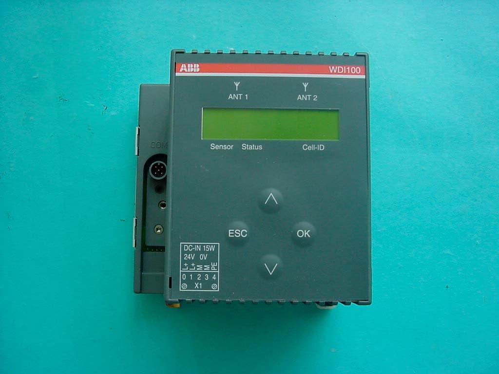
R4T-WDI100
Jun 06, 2004FHSS Transceiver
Equipment Class
DSS - Part 15 Spread Spectrum Transmitter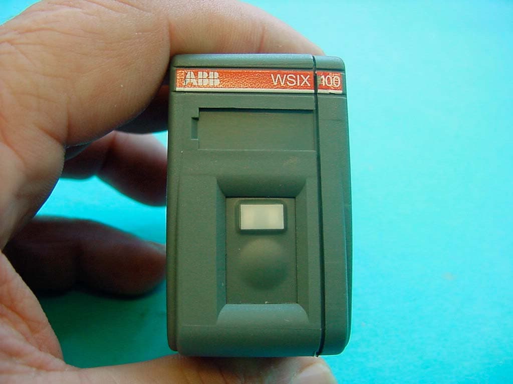
R4T-WSIX100
Jun 06, 2004FHSS Transceiver
Equipment Class
DSS - Part 15 Spread Spectrum Transmitter