R7PER6R1S2M120 Module
Landis+Gyr Technology, Inc.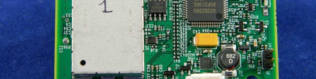
Click to zoom
Application Details
- Equipment Class
- DXT - Part 15 Low Power Transceiver, Rx Verified
- Date of Grant
- Jun 22, 2015
- Application Purpose
- Original Equipment
- Date of Application
- Jun 22, 2015
- Equipment Note
- M120 Module
- Frequency Range
- 902.30000000 - 927.50000000
- Company
- Landis+Gyr Technology, Inc.
- Country
- United States
Documents & Files
Document Text
Text extracted from the exhibit documents filed with the FCC. Open a document above to read the original.
Users Manual
5015 B.U. Bowman Drive Buford, GA 30518 USA Voice: 770-831-8048 Fax: 770-831-8598 Certification Exhibit FCC ID: R7PER6R1S2 FCC Rule Part: 15.247, 15.249 ACS Project Number: 15-0174 Manufacturer: Landis+Gyr Technology, Inc. Model: M120 LANDIS+GYR CONFIDENTIAL INFORMATION M120 Module User Guide Publication: 98-1718 Rev AA Limitation on Warranties and Liability Information in this document is subject to change without notice. This manual or any part of it thereof may not be re- produced in any form unless permitted by contract or by written permission of Landis+Gyr. In no event will Landis+Gyr be liable for any incidental, indirect, special, or consequential damages (including lost prof- its) arising out of or relating to this publication or the information contained in it, even if Landis+Gyr has been advised, knew, or should have known of the possibility of such damages. © 2015 Landis+Gyr, Inc. All Rights Reserved M120 Module User Guide Publication: 98-1718 Revision History Modification DateRevisionDescriptionAuthor 06/09/2015AAReleasedCharlie Goerges © 2015 Landis+Gyr • All rights reserved. User Guide98-1718 Rev AA3 M120 Module User Guide Introduction The M120 is a battery operated module designed for automated gas meter reading. The M120 is capable of recording gas consumption data from residential gas meters. It has a 2-way radio that is compatible with electric meters, routers, and mesh extenders for relaying sensor data to the utility. Federal Communication Commission (FCC) Compliance Notice This device complies with Part 15 of the FCC rules. Operation is subject to the following two conditions: 1.This device may not cause harmful interference, and 2.This device must accept any interference received, including interference that may cause undesired operation. This equipment has been tested and found to comply with the limits for a Class B digital device, pursuant to Part 15 of the FCC Rules. These limits are designed to provide reasonable protection against harmful interference in a residential installation. This equipment generates, uses, and can radiate radio frequency energy and, if not installed and used in accordance with the instructions, may cause harmful interference to radio communications. However, there is no guarantee that interference will not occur in a particular installation. If this equipment does cause harmful interference to radio or television reception, which can be determined by turning the equipment off and on, the user is encouraged to try to correct the interference by one or more of the following measures: 1.Reorient or relocate the receiving antenna. 2.Increase the separation between the equipment and receiver. 3.Consult Landis+Gyr or an experienced radio technician for help. UWARNING: Changes or modifications to this device not expressly approved by Landis+Gyr will void the equipment warranty. M120 Module User GuideLandis+Gyr 498-1718 Rev AAUser Guide Host FCC Label Requirements The host label(s) must be clearly visible after the device is installed, and display the module FCC ID in the following format: Contains FCC ID: R7PER6R1S2 The following statement must also be clearly visible: This device complies with part 15 of the FCC Rules. Operation is subject to the following two conditions: (1) This device may not cause harmful interference, and (2) this device must accept any interference received, including interference that may cause undesired operation. RF Exposure Information In accordance with FCC requirements of human exposure to radio frequency fields, the radiating element shall be installed such that a minimum separation distance of 20 centimeters (8 inches) will be maintained. Electrical Characteristics Battery: •Battery type: Lithium-Manganese Dioxide •Nominal voltage: 3.0 V •Capacity: 4800 mAh •Landis+Gyr Part number: 40-1235 DC Characteristics: •Operating Voltage Range: 2.4 V - 3.3 V •Typical Sleep Current: 7 uA Radio Characteristics: •Typical Antenna Gain: 0 dBi •Frequency Range: 902 MHz - 928 MHz •Modulation Format: FSK •Transmit Output Power (typical) •Single Channel Mode: - 27 dBm •Frequency Hopping Mode: 24 dBm •Receive sensitivity (typical) Landis+GyrM120 Module User Guide User Guide98-1718 Rev AA5 •9.6 kbps: -112 dBm •19.2 kbps: -110 dBm •38.4 kbps: -108 dBm •115.2 kbps: -101 dBm •Max Input Power, No Damage: 10 dBm Functional Description The M120 is a wireless battery endpoint for the application of automatic gas meter reading. The primary function of the module is to record pulses that represent measurement of gas consumption, and then deliver the data to the utility for processing. The block diagram below demonstrates this operation. Figure 1. Operation Block Diagram The module is designed to record pulses from a Form-C type pulse initiator. The pulse initiator is a sensor board that measures gas volume flow and relays the measurement to the M120 in the form of electrical pulses. The radio has two operating modes, frequency hopping and single channel. The frequency hopping mode is the normal operating mode for network communication. The single channel mode is a low power mode, and is primarily used for field diagnostic purposes. M120 Module User GuideLandis+Gyr 698-1718 Rev AAUser Guide Host Installation The battery is connected to the battery connector. The sensor board is connected to the M120 through a flex-cable. See picture below. Figure 2. Sensor Board and Battery Connection to M120 Module The M120 module and sensor board (pulse initiator) are designed to be heat-staked inside a plastic enclosure. See picture below. Figure 3. M120 Module and Sensor Board Staking Locations Battery Connector Sensor Board Flex Cable M120 Module HEAT STAKE THESE PINS TO HOLD SENSOR BOARD TO HOST HEAT STAKE THESE PINS TO HOLD FLEX-CABLE TO HOST HEAT STAKE THESE TWO PINS TO HOLD M120 TO HOST
Cover Letter(s)
30000 Mill Creek Avenue, Suite 100 | Alpharetta, GA 30022 Tel: +1 678 258 1637 | Fax: +1 678 258 1681 Date: June 10, 2015 Federal Communications Commission Equipment Authorization Branch 7435 Oakland Mills Rd. Columbia, MD 21046 Dear Sir or Madam: I hereby appoint Sam Wismer at Advanced Compliance Solutions, Inc. to act as our agent in the preparation of an application for equipment authorization of FCC ID: R7PER6R1S2 to the FCC Rules and Regulations. I certify that all exhibits contained within this filing properly describe the device or system for which authorization is sought. I further certify that appropriate arrangements have been made to assure that production units of this equipment bearing the name and FCC IDENTIFIER listed in this application will continue to comply with the Commission's requirements. I further certify by signature below that no party (per 47 CFR 1.2002(b)) to the application is subject to a denial of Federal benefits, including FCC benefits, pursuant to Section 5301 of the Anti-Drug Abuse Act of 1988, 21 U.S.C. 853(a). This appointment also includes the authority to complete FCC Form 731 on our behalf and sign the application as an authorized agent. Sincerely, Name: Richard Timko Title: Quality Engineer
Cover Letter(s)
30000 Mill Creek Avenue, Suite 100 | Alpharetta, GA 30022 Tel: +1 678 258 1637 | Fax: +1 678 258 1681 CONFIDENTIALITY REQUEST Federal Communications CommissionDate: June 10, 2015 Equipment Authorization Branch 7435 Oakland Mills Road Columbia, MD 21046 Gentlemen: Landis+Gyr Technology, Inc. respectfully requests confidentiality of certain materials provided with the submission of the “M120” under FCC ID: R7PER6R1S2 in accordance with 47 CFR 0.457(d) and 47 CFR 0.459. The confidentiality request applies to the System Block Diagram, Schematics, and Theory of Operation contained in this filing and included in the following files. 15-0174 – Schematics.pdf 15-0174 – System Block Diagram.pdf 15-0174 – Theory of Operation.pdf The “M120” has been developed at considerable effort and expense by Landis+Gyr Technology, Inc. These items are considered as Trade Secrets and therefore public access to the proprietary material could possibly result in duplication of equipment that could severely damage the company's business advantage. I appreciate your assistance in this matter. Sincerely, Name: Richard Timko Title: Quality Engineer
Cover Letter(s)
5015 B. U. Bowman Dr. Buford, GA 30518 June 11, 2015 ACS TCB 5015 B.U. Bowman Drive Buford, GA 30518 Re: FCC ID: R7PER6R1S2 To Whom It May Concern: The following application is submitted on behalf of our client, Landis+Gyr Technology, Inc., for evaluation of their model M120 for certification under FCC Part 15.247 and 15.249. The M120 is a battery operated module operating in the 902 – 928 MHz frequency band. The M120 is designed for automated gas meter reading and has a 2-way radio that is compatible with electric meters, routers, and mesh extenders for relaying sensor data to the utility. The M120 operates utilizing a high power frequency hopping mode under FCC Part 15.247 and low power single channel mode under FCC Part 15.249. The M120 was tested in full to the requirements of the aforementioned rules and was found to be in compliance. Sincerely, Sam Wismer Vice President, Technology Advanced Compliance Solutions, Inc.
Cover Letter(s)
30000 Mill Creek Avenue, Suite 100 | Alpharetta, GA 30022 Tel: +1 678 258 1637 | Fax: +1 678 258 1681 To:File From:Richard Timko Subject:M120, FCC ID: R7PER6R1S2 Modular Approval RequestJune 10, 2015 Scope 47CFR 15.212 communicates requirements for products requesting modular approval. In particular, eight requirements are enumerated along with a request that each of the eight be explained for any product requesting such approval. It is the purpose of this document to respond to those eight requirements in regard to the Landis+Gyr product: M120. Modular Approval Requirements 1.1 RF Shielding The M120 module is self-shielding and is not dependent on any component or characteristic of the device into which it is embedded. Shielding is accomplished through a combination of metallic self-shielding components, copper planes, guards, and vias in the PCB. The result is a design that has been proven to be neither sensitive to outside influence nor capable of introducing interference into outside components. 1.2Buffered Modulation / Data Inputs The M120 module does not have external modulation or data inputs. Rather, the RF sections are driven by an on-board microprocessor which directly controls the RF data lines and operates so as to not allow excessive modulation. 1.3Power Supply Regulation The M120 module uses linear, low-dropout regulators to provide all the electronics with a supply that is fixed, even when the input voltage is varied. 1.4Antenna Requirement The M120 module utilizes an internal, integrated, inverted-F antenna. 1.5Stand-Alone Testing All testing on the M120 module was conducted standalone. No shields or enclosures were used, other than those fully integrated into the modules themselves. No ferrites were used on data or power lines during testing. These devices are DC powered, and exceed applicable conducted emission requirements. 1.6Labeling As indicated, each M120 module will have its own FCC ID label. In addition, devices into which they are placed will have labels indicating that this module is contained within. Exact text will be as specified in 47CFR 15.212. 1.7Specific Rules and Operating Requirements The M120 module complies with all pertinent rules for its section. 1.8RF Exposure Requirements The M120 module complies with all exposure requirements. As a component used in the Utility industry, this product is not intended for use near human operators. 2.0In Reference to 15.212(b) The M120 module is always professionally installed and is not sold to the general public. This module undergoes continuous, rigorous testing to ensure that full compliance is always maintained. Sincerely, Title: Quality Engineer
External Photos
5015 B.U. Bowman Drive Buford, GA 30518 USA Voice: 770-831-8048 Fax: 770-831-8598 Certification Exhibit FCC ID: R7PER6R1S2 FCC Rule Part: 15.247, 15.249 ACS Project Number: 15-0174 Manufacturer: Landis+Gyr Technology, Inc. Model: M120 Model: M120FCC ID: R7PER6R1S2 ACS Project: 15-0174Advanced Compliance SolutionsPage 2 Figure 1: External Photo Figure 2: External Photo
ID Label/Location Info
5015 B.U. Bowman Drive Buford, GA 30518 USA Voice: 770-831-8048 Fax: 770-831-8598 Certification Exhibit FCC ID: R7PER6R1S2 FCC Rule Part: 15.247, 15.249 ACS Project Number: 15-0174 Manufacturer: Landis+Gyr Technology, Inc. Model: M120
Internal Photos
5015 B.U. Bowman Drive Buford, GA 30518 USA Voice: 770-831-8048 Fax: 770-831-8598 Certification Exhibit FCC ID: R7PER6R1S2 FCC Rule Part: 15.247, 15.249 ACS Project Number: 15-0174 Manufacturer: Landis+Gyr Technology, Inc. Model: M120 Model: M120FCC ID: R7PER6R1S2 ACS Project: 15-0174Advanced Compliance SolutionsPage 2 Figure 1: Internal Photo – Shield Removed Figure 2: Internal Photo – Shield Removed
Test Report
5015 B.U. Bowman Drive Buford, GA 30518 USA Voice: 770-831-8048 Fax: 770-831-8598 Certification Test Report FCC ID: R7PER6R1S2 FCC Rule Part: 15.249 ACS Report Number: 15-0174.W03.2A Manufacturer: Landis+Gyr Technology, Inc. Model: M120 Test Begin Date: May 7, 2015 Test End Date: May 8, 2015 Report Issue Date: June 11, 2015 FOR THE SCOPE OF ACCREDITATION UNDER LAB Code 200612-0 This report must not be used by the client to claim product certification, approval, or endorsement by NVLAP, NIST, or any agency of the Federal Government. Reviewed by: Kirby Munroe Director, Wireless Certifications ACS, Inc. This test report shall not be reproduced except in full. This report may be reproduced in part with prior written consent of ACS, Inc. The results contained in this report are representative of the sample(s) submitted for evaluation. This report contains 15 pages 5015 B.U. Bowman Drive Buford, GA 30518 USA Voice: 770-831-8048 Fax: 770-831-8598 TABLE OF CONTENTS 1 GENERAL ............................................................................................................................................ 3 1.1 PURPOSE .......................................................................................................................................... 3 1.2 PRODUCT DESCRIPTION ................................................................................................................... 3 1.3 TEST METHODOLOGY AND CONSIDERATIONS ................................................................................. 4 2 TEST FACILITIES .............................................................................................................................. 5 2.1 LOCATION ....................................................................................................................................... 5 2.2 LABORATORY ACCREDITATIONS/RECOGNITIONS/CERTIFICATIONS ................................................ 5 2.3 RADIATED EMISSIONS TEST SITE DESCRIPTION .............................................................................. 6 2.3.1 Semi-Anechoic Chamber Test Site .......................................................................................... 6 2.3.2 Open Area Tests Site (OATS) ................................................................................................. 7 2.4 CONDUCTED EMISSIONS TEST SITE DESCRIPTION ........................................................................... 8 3 APPLICABLE STANDARD REFERENCES .................................................................................... 8 4 LIST OF TEST EQUIPMENT ............................................................................................................ 9 5 SUPPORT EQUIPMENT ...................................................................................................................10 6 EQUIPMENT UNDER TEST SETUP BLOCK DIAGRAM ..........................................................10 7 SUMMARY OF TESTS ......................................................................................................................11 7.1 ANTENNA REQUIREMENT – FCC 15.203 ........................................................................................11 7.2 POWER LINE CONDUCTED EMISSIONS – FCC 15.207 .....................................................................11 7.3 20DB BANDWIDTH – FCC 15.215 ..................................................................................................11 7.3.1 Measurement Procedure ........................................................................................................11 7.3.2 Measurement Results .............................................................................................................11 7.4 FUNDAMENTAL FIELD STRENGTH – FCC 15.249(A) .......................................................................13 7.4.1 Measurement Procedure ........................................................................................................13 7.4.2 Measurement Results .............................................................................................................13 7.5 RADIATED SPURIOUS EMISSIONS – FCC 15.249(A)(D)(E) ..............................................................14 7.5.1 Measurement Procedure ........................................................................................................14 7.5.2 Measurement Results .............................................................................................................14 7.5.3 Sample Calculation: ..............................................................................................................14 8 CONCLUSION ....................................................................................................................................15 Model: M120 FCC ID: R7PER6R1S2 ACS Report: 15-0174.W03.2A Advanced Compliance Solutions Page 3 1 GENERAL 1.1 Purpose The purpose of this report is to demonstrate compliance with Part 15 Subpart C of the FCC’s Code of Federal Regulations for modular approval certification. 1.2 Product description The M120 is a battery operated module operating in the 902 – 928 MHz frequency band. The M120 is designed for automated gas meter reading and has a 2-way radio that is compatible with electric meters, routers, and mesh extenders for relaying sensor data to the utility. Technical Information: The model M120 provides two distinct modes of operation; frequency hopping mode at high power, and single channel mode at low power. This report addresses the single channel mode as outlined below. Mode of Operation Frequency Range (MHz) Number of Channels Channel Separation (kHz) Data Rates Supported (kbps) 1 902.3 - 927.5 64 400 115.2 Modulation Format: FSK/GFSK Antenna Type / Gain: Inverted F / 2dBi gain Operating Voltage: 3VDC (Internal Battery) Manufacturer Information: Landis+Gyr Technology, Inc. 30000 Mill Creek Ave., Suite 100 Alpharetta, GA 30022 EUT Serial Number…
Text truncated - open the document above for the full version.
Test Setup Photos
5015 B.U. Bowman Drive Buford, GA 30518 USA Voice: 770-831-8048 Fax: 770-831-8598 Certification Exhibit FCC ID: R7PER6R1S2 FCC Rule Part: 15.247, 15.249 ACS Project Number: 15-0174 Manufacturer: Landis+Gyr Technology, Inc. Model: M120 Model: M120FCC ID: R7PER6R1S2 ACS Project: 15-0174Advanced Compliance SolutionsPage 2 Figure 1: Radiated Emissions – XPOS Figure 2: Radiated Emissions – XPOS Model: M120FCC ID: R7PER6R1S2 ACS Project: 15-0174Advanced Compliance SolutionsPage 3 Figure 3: Radiated Emissions – YPOS Figure 4: Radiated Emissions – YPOS Model: M120FCC ID: R7PER6R1S2 ACS Project: 15-0174Advanced Compliance SolutionsPage 4 Figure 5: Radiated Emissions – YPOS Figure 6: Radiated Emissions – ZPOS Model: M120FCC ID: R7PER6R1S2 ACS Project: 15-0174Advanced Compliance SolutionsPage 5 Figure 7: Radiated Emissions – ZPOS
Contact Information
Applicant
James L Stortz(Director of Hardware Engineering)
Test Firm
Advanced Compliance Solutions, Inc.Randy Abernathy
Technical Specifications
| # | Rule Parts | Frequency Range | Power Output |
|---|---|---|---|
| 1 | 15C | 902.3 MHz - 927.5 MHz | - |
Other Applications from Landis+Gyr Technology, Inc.
R7PMGZW1A1
May 01, 2026S2 EIC WiFi Chip
Equipment Class
DTS - Digital Transmission System
R7PMGBM2B1
Jan 08, 2024Series-6 Gen-2 MCM0
Equipment Class
DTS - Digital Transmission System
R7PNG0R1X8
Jul 18, 2022Electricity Meter Module
Equipment Class
DSS - Part 15 Spread Spectrum Transmitter
R7PNG0R1S5
Aug 19, 2020Series 5 mPCIe Module
Equipment Class
DSS - Part 15 Spread Spectrum Transmitter
R7PEG1R1S7
May 20, 2020LTE-M Cellular Communication Module
Equipment Class
DTS - Digital Transmission System