R7PMGBM2B1Series-6 Gen-2 MCM0
Landis+Gyr Technology, Inc.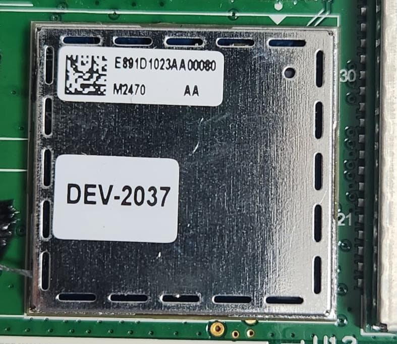
Click to zoom
Application Details
- Equipment Class
- DTS - Digital Transmission System
- Date of Grant
- Jan 08, 2024
- Application Purpose
- Original Equipment
- Date of Application
- Dec 17, 2023
- Equipment Note
- Series-6 Gen-2 MCM0
- Frequency Range
- 902.80000000 - 926.80000000
- Company
- Landis+Gyr Technology, Inc.
- Country
- United States
Documents & Files
Document Text
Text extracted from the exhibit documents filed with the FCC. Open a document above to read the original.
Users Manual
D8051 Draft Data Sheet Series-6 Gen-2 MCM0.docx D8051 Rev AA Friday, December 08, 2023 Landis+Gyr Draft 08.12.2023 Series-6 Gen-2 MCM0 Data Sheet D8051 Draft Data Sheet Series-6 Gen-2 MCM0.docx D8051 Rev AA Friday, December 08, 2023 Landis+Gyr Limitation on Warranties and Liability Information in this document is subject to change without notice. This manual or any part of it thereof may not be reproduced in any form unless permitted by contract or by written permission of Landis+Gyr. In no event will Landis+Gyr be liable for any incidental, indirect, special, or consequential damages (including lost profits) arising out of or relating to this publication or the information contained in it, even if Landis+Gyr has been advised, knew, or should have known of the possibility of such damages. Covered by both issued and pending patents. For further patent information see: https://www.landisgyr.com/about/patent-notices/ © 2022 Landis+Gyr, Inc. | Proprietary + Confidential Contact Us: To provide feedback about this document, email us at [email protected] Customer Support: 1-888-390-5733 | [email protected] D8051 Rev AA | Series-6 Gen-2 MCM0 (S6G2-MCM0) Data Sheet | Release Date Pending D8051 Draft Data Sheet Series-6 Gen-2 MCM0.docx D8051 Rev AA Friday, December 08, 2023 Landis+Gyr Introduction Landis+Gyr's Series-6 Gen-2 MCM0 (S6G2-MCM0) is key to building a single, integrated IoT network for your utility future. This product is a fully functional Network Interface Card (NIC) in a multi-chip module form-factor to enable low- cost network and sensor device integration. This technology is foundational to Landis+Gyr's industry-leading utility IoT networking solution, Gridstream® Connect. Furthermore, the S6G2-MCM0 provides the flexibility to grow the value of your IoT platform over time with proven Wi-SUN FAN interoperability as you integrate todays and future AMI or DA networking equipment and third-party IoT devices. The device supports RF Mesh (GSP), Mesh IP (SBS) and Wi-SUN (WSN) FW stacks. Figure 1. Series-6 Gen-2 MCM 0 Table - 1. Technical Specifications Element Description Radio Model Series-6 Gen-2 MCM0 Communication Protocol (PHY) IEEE 802.15.4-2020 MAC/PHY Features MAC Automatic selection of ‘best’ Band based on Link Quality Automatic selection of ‘best’ Modulation based on Link Quality PHY Adaptive Power Control Precision Output Power Management Clear Channel Assessment Hardware Capabilities RF Modulation IEEE 802.15.4 SUN FSK & OFDM RF Bands 902 – 928 MHz D8051 Draft Data Sheet Series-6 Gen-2 MCM0.docx D8051 Rev AA Friday, December 08, 2023 Landis+Gyr Table - 1. Technical Specifications (Continued) Element Description RF Ports 1 Table - 2. Sub-GHz Band Characteristics: North America Network Operating Mode RF Mesh IP Series 5 Compatible RF Mesh IP Green Field Wi-SUN Frequency Range (Fc) 902.4 MHz - 927.6 MHz 904 MHz - 926.8 MHz 902.2 MHz – 927.8 MHz Channel Width 400 KHz 1200 kHz 200, 400, 800 & 1200 kHz Number of Channels 64 20 129, 64, 31 & 21 Multicast Modulation 2-FSK 50 kbps OFDM Option 1 MCS0 (100 kbps) 2-FSK 50 kbps 2-FSK: 50 - 200 kbps 2-FSK: 50 - 200 kbps OFDM Option 3: MCS2 - MCS3 (100 - 200 kbps) Unicast Modulation Support OFDM Option 3: MCS3 - MCS6 OFDM Option 1: MCS0 - MCS6 OFDM Option 2: MCS3 - MCS5 (400 - 800 kbps) OFDM Option 1: MCS5 - MCS6 (1600 - 2400 kbps) Data Rate Coverage 50 kbps - 600 kbps 100 kbps - 2400 kbps 50 kbps - 2400 kbps Transmitter Output Power 10 mW - 631 mW (peak) 10 mW - 200 mW 10 mW - 631 mW (peak) Receiver Sensitivity (IEEE 802.15.4) TBD TBD TBD D8051 Draft Data Sheet Series-6 Gen-2 MCM0.docx D8051 Rev AA Friday, December 08, 2023 Landis+Gyr S6G2-MCM0 Outline The PCB outline is shown below: Figure 2. PCB Outline 1 Figure 3. PCB Outline 2 D8051 Draft Data Sheet Series-6 Gen-2 MCM0.docx D8051 Rev AA Friday, December 08, 2023 Landis+Gyr FCC and Industry Canada Compliance FCC ID for Series-6 Gen-2 MCM0: R7PMGBM2B1 ISED for Series-6 Gen-2 MCM0:5294A-MGBM2B1 FCC Class B This device complies with Part 15 of the FCC rules. Operation is subject to the following two conditions: • This device may not cause harmful interference, and • This device must accept any interference received, including interference that may cause undesired operation. This equipment has been tested and found to comply with the limits for a Class B digital device, pursuant to Part 15 of the FCC Rules. These limits are designed to provide reasonable protection against harmful interference in a residential installation. This equipment generates, uses, and can radiate radio frequency energy and, if not installed and used in accordance with the Instructions, may cause harmful interference to radio communications. However, there is no guarantee that interference will not occur in a particular installation. If this equipment does cause harmful interference to radio or television reception, which can be determined by turning the equipment off and on, the user is encouraged to try to correct the interference by one or more of the following measures: • Reorient or relocate the receiving antenna. • Increase the separation between the equipment and receiver. • Consult Landis+Gyr or an experienced radio technician for help. WARNING: Changes or modifications to this device not expressly approved by Landis+Gyr could void the user’s authority to operate the equipment. D8051 Draft Data Sheet Series-6 Gen-2 MCM0.docx D8051 Rev AA Friday, December 08, 2023 Landis+Gyr RF Exposure This equipment complies with FCC radiation exposure limits set forth for an uncontrolled environment. This equipment should be installed and operated with minimum distance 20 cm between the radiator and your body. The antenna(s) used for this transmitter must not transmit simultaneously with any other antenna or transmitter, except in accordance with FCC multi-transmitter product procedures. Cet équipement est conforme aux limites FCC/ISED d'exposition aux radiations définies pour un environnement no…
Text truncated - open the document above for the full version.
Attestation Statements
30000 Mill Creek Avenue, Suite 100 | Alpharetta, GA 30022 Tel: +1 678 258 1637 | Fax: +1 678 258 1681 Federal Communications Commission Authorization and Evaluation Division 7435 Oakland Mills Rd. Columbia, MD 21046 USA August 21, 2023 Ref: Attestation Statements Part 2.911(d)(5)(i) and Part 2.911(d)(5)(ii) Filing Re. KDB 986446 D01 FCC ID: R7PMGBM2B1 Dear Sir or Madam, Landis+Gyr Technology, Inc (“the applicant”) certifies that the equipment for which authorization is sought is not “covered” equipment prohibited from receiving an equipment authorization pursuant to section 2.903 of the FCC rules. We also certify that, as of the date of the filing of the application, the applicant is not identified on the Covered List as an entity producing “covered” equipment. If you have any questions, please contact us. Sincerely, James L. Stortz Title: Head of Communication Hardware Delivery Landis+Gyr Technology, Inc 30000 Mill Creek Ave, Suite 100, Alpharetta GA 30022 [email protected] (678) 258 1434
Attestation Statements
30000 Mill Creek Avenue, Suite 100 | Alpharetta, GA 30022 Tel: +1 678 258 1637 | Fax: +1 678 258 1681 Federal Communications Commission Authorization and Evaluation Division 7435 Oakland Mills Rd. Columbia, MD 21046 USA August 21, 2023 Ref: Attestation Statements Part 2.911(d)(7) Filing FCC ID: R7PMGBM2B1 Landis+Gyr Technology, Inc (“the applicant”) certifies that, as of the date of the filing of the application, Landis+Gyr Technology, Inc is our designated U.S. agent for service of process for the above referenced FCC ID. Landis+Gyr Technology, Inc accepts to maintain an agent for no less than one year after the grantee has terminated all marketing and importation or the conclusion of any Commission-related proceeding involving the equipment. Landis+Gyr Technology, Inc accepts, as of the date of the filing of the application, the obligation of the designated U.S. agent for service of process for the above referenced FCC ID. Designated U.S. Agent Information: Name: Landis+Gyr Technology, Inc Address: 30000 Mill Creek Ave, Suite 100, Alpharetta GA 30022 Contact Person: James L. Stortz Tel.: (678) 258 1434 Email: [email protected] FRN: 0011025368 Sincerely, Landis+Gyr Technology, Inc James L. Stortz Title: Head of Communication Hardware Delivery
Cover Letter(s)
30000 Mill Creek Avenue, Suite 100 | Alpharetta, GA 30022 Tel: +1 678 258 1637 | Fax: +1 678 258 1681 Date: August 07, 2023 Federal Communications Commission Equipment Authorization Branch 7435 Oakland Mills Rd. Columbia, MD 21046 Dear Sir or Madam: I hereby appoint Mr. Raghavendra Kulkarni at TUV Rheinland India Pvt Ltd. to act as our agent in the preparation of an application for equipment authorization of FCC ID: R7PMGBM2B1 to the FCC Rules and Regulations. I certify that all exhibits contained within this filing properly describe the device or system for which authorization is sought. I further certify that appropriate arrangements have been made to assure that production units of this equipment bearing the name and FCC IDENTIFIER listed in this application will continue to comply with the Commission's requirements. I further certify by signature below that no party (per 47 CFR 1.2002(b)) to the application is subject to a denial of Federal benefits, including FCC benefits, pursuant to Section 5301 of the Anti-Drug Abuse Act of 1988, 21 U.S.C. 853(a). This appointment also includes the authority to complete FCC Form 731 on our behalf and sign the application as an authorized agent. Sincerely, James L. Stortz Title: Head of Communication Hardware Delivery
Cover Letter(s)
Printed Inverted F Antenna Data Sheet Antenna Model Number: Printed Inverted F Technical details of Antenna provided below: Dielectric constant: 4.3 +/-0.2 @ 1GHz. Isolation between S6G2-MCM0 & PCB Printed IFA: S6G2-MCM0 RF Port is connected to Host Printed IFA without any RF pad attenuator in between. Procedure for Antenna Design Verification: Below is the list of tests performed to verify Antenna’s design performance. 1. S-parameters characterization 2. Radiation Pattern Measurement 3. ERP measurement 4. Radiated Sensitivity measurement Shown below are the dimensions of Printed Inverted F Antenna. Radiation Pattern results of this Antenna are shown below. Tx Radiated Power PSET = 27 dBm Mode = F2B50 Freq (MHz) 902.4 Frequency Antenna Type Max Gain (dBi) Impedance (Typical) 902-928 MHz PCB Printed Inverted F Antenna 1.0 50 ohms Freq (MHz) 914.8 Freq (MHz) 927.6
Cover Letter(s)
30000 Mill Creek Avenue, Suite 100 | Alpharetta, GA 30022 Tel: +1 678 258 1637 | Fax: +1 678 258 1681 CONFIDENTIALITY REQUEST Date: August 07, 2023 Federal Communications Commission Equipment Authorization Branch 7435 Oakland Mills Road Columbia, MD 21046 Gentlemen: Landis+Gyr Technology, Inc. respectfully requests confidentiality of certain materials provided with the submission of the Series-6 Gen-2 MCM0 under FCC ID: R7PMGBM2B1 in accordance with FCC Regulations 0.459. The confidentiality request applies to the System Block Diagram, Schematics, Parts List, and Theory of Operation contained in this filing. Series-6 Gen-2 MCM0 has been developed at considerable effort and expense by Landis+Gyr Technology, Inc. These items are considered as Trade Secrets and therefore public access to the proprietary material could possibly result in duplication of equipment that could severely damage the company's business advantage. I appreciate your assistance in this matter. Sincerely, James L. Stortz Title: Head of Communication Hardware Delivery
Cover Letter(s)
30000 Mill Creek Avenue, Suite 100 | Alpharetta, GA 30022 Tel: +1 678 258 1637 | Fax: +1 678 258 1681 To: File From: James L. Stortz Subject: Series-6 Gen-2 MCM0, FCC ID: R7PMGBM2B1 Modular Approval Request August 29, 2023 Scope 47CFR 15.212 communicates requirements for products requesting modular approval. In particular, eight requirements are enumerated along with a request that each of the eight be explained for any product requesting such approval. It is the purpose of this document to respond to those eight requirements in regard to the Landis+Gyr product: Series-6 Gen-2 MCM0. Modular Approval Requirements 1.1 RF Shielding The Series-6 Gen-2 MCM0 module is self-shielding and is not dependent on any component or characteristic of the device into which it is embedded. Shielding is accomplished through a combination of metallic self-shielding components, copper planes, guards, and vias in the PCB. The result is a design that has been proven to be neither sensitive to outside influence nor capable of introducing interference into outside components. 1.2 Buffered Modulation / Data Inputs The Series-6 Gen-2 MCM0 module does not have external modulation or data inputs. Rather, the RF sections are driven by an on-board microprocessor which directly controls the RF data lines and operates so as to not allow excessive modulation. 1.3 Power Supply Regulation The Series-6 Gen-2 MCM0 module uses linear, low-dropout regulators to provide all the electronics with a supply that is fixed, even when the input voltage is varied. 1.4 Antenna Requirement The Series-6 Gen-2 MCM0 module is does not come with an antenna. It is designed to be integrated with a host board that provides the antenna. 1.5 Stand-Alone Testing All testing on the Series-6 Gen-2 MCM0 module was conducted standalone, on a host board. No shields or enclosures were used, other than those fully integrated into the modules themselves. No ferrites were used on data or power lines during testing. These devices are DC powered, and exceed applicable conducted emission requirements. 1.6 Labeling The Series-6 Gen-2 MCM0 is a small printed-circuit board module that will be supplied on reel. The FCC ID will be on a label placed on the reel. In addition, devices into which they are placed will have labels indicating that this module is contained within. Exact text will be as specified in 47CFR 15.212. 1.7 Specific Rules and Operating Requirements The Series-6 Gen-2 MCM0 module complies with all pertinent rules for its section. 1.8 RF Exposure Requirements The Series-6 Gen-2 MCM0 module complies with all exposure requirements. As a component used in the Utility industry, this product is not intended for use near human operators. 2.0 In Reference to 15.212(b) The Series-6 Gen-2 MCM0 module is always professionally installed and is not sold to the general public. This module undergoes continuous, rigorous testing to ensure that full compliance is always maintained. Sincerely, James L. Stortz Title: Head of Communication Hardware Delivery
External Photos
Produkte Products www.tuv.com External Photos Reference Test Report No: IN23VZM3 001 & IN23RA4Z 001 Seite 1 von 2 Page 1 of 2 External Photos Photo 1: DUT Front View Photo 2: DUT Front View Produkte Products www.tuv.com External Photos Reference Test Report No: IN23VZM3 001 & IN23RA4Z 001 Seite 2 von 2 Page 2 of 2 Photo 3: DUT with Evaluation board
ID Label/Location Info
Series-6 Gen-2 MCM0 FCC/IC Label Information Series-6 Gen-2 MCM0 is a modular approved radio module. The label requirement is as follows. For the Series-6 Gen-2 MCM0, the label will be populated with the FCC/IC information below. Model: Series-6 Gen-2 MCM0 FCC ID: R7PMGBM2B1 IC: 5294A-MGBM2B1 Due to size limitations this label is placed on the reel and packaging material containing the module.
Internal Photos
Produkte Products www.tuv.com Internal Photos Reference Test Report No: IN23VZM3 001 & IN23RA4Z 001 Seite 1 von 2 Page 1 of 2 Internal Photos Device Front View Device Rear View Produkte Products www.tuv.com Internal Photos Reference Test Report No: IN23VZM3 001 & IN23RA4Z 001 Seite 2 von 2 Page 2 of 2 Module With Shield Module Without Shield
RF Exposure Info
Prüfbericht – Produkte Test Report - Products Prüfbericht-Nr.: Test report no.: IN23RA4Z 001 & IN23VZM3 001 Auftrags-Nr.: Order no.: 146800530 0010 Seite 1 von 4 Page 1 of 4 Kunden-Referenz-Nr.: Client reference no.: 2142863 Auftragsdatum: Order date: 2023-06-01 Auftraggeber: Client: Landis + Gyr Technology, Inc. 30000 Mill Creek Ave., Suite 100 Alpharetta, GA 30022 Prüfgegenstand: Test item: Sub-GHz Wireless Mesh Module Bezeichnung Identification Series-6 Gen-2 MCM0 Serien -Nr.: Serial no.: D016E7A9 & D016E7BC Auftrags-Inhalt: Order content: Maximum Permissible Expsoure Prüfgrundlage: Test specification: FCC 1.1310, and RSS 102 Issue 5 KDB 447498 D01 Wareneingangsdatum: Date of sample receipt: 2023-06-19 Prüfmuster-Nr.: Test sample no: A003499438-001 & A003499438- 003 Prüfzeitraum: Testing period: 2023-06-19 - 2023-07-29 Ort der Prüfung: Place of testing: Wireless laboratory, Bangalore Prüflaboratorium: Testing laboratory: TÜV Rheinland (India) Pvt. Ltd. 27/B,2nd cross road, Electronic city Phase1, Banglore-560100, India FCC Test Site Registration No: 496599 IC Test Site Registration No: 27711 HVIN: Series-6 Gen-2 MCM0 Prüfergebnis*: Test result*: Pass geprüft von: tested by: genehmigt von: authorized by: Datum: Date: 2023-07-31 Ausstellatum: Issue date: 2023-10-16 Stellung / Position: M.V.Naveen Kumar Senior Engineer Stellung / Position: Madhu K.N Assistant Manager Sonstiges / Other: FCC ID: R7PMGBM2B1 IC : 5294A-MGBM2B1 Zustand des Prüfgegenstandes bei Anlieferung: Condition of the test item at delivery: Prüfmuster vollständig und unbeschädigt Test item complete and undamaged * Legende: 1 = sehr gut 2 = gut 3 = befriedigend 4 = ausreichend 5 = mangelhaft P(ass) = entspricht o.g. Prüfgrundlage(n) F(ail) = entspricht nicht o.g. Prüfgrundlage(n) N/A = nicht anwendbar N/T = nicht getestet * Legend: 1 = very good 2 = good 3 = satisfactory 4 = sufficient 5 = poor P(ass) = passed a.m. test specification(s) F(ail) = failed a.m. test specification(s) N/A = not applicable N/T = not tested Dieser Prüfbericht bezieht sich nur auf das o.g. Prüfmuster und darf ohne Genehmigung der Prüfstelle nicht auszugsweise vervielfältigt werden. Dieser Bericht berechtigt nicht zur Verwendung eines Prüfzeichens. This test report only relates to the a. m. test sample. Without permission of the test center this test report is not permitted to be duplicated in extracts. This test report does not entitle to carry any test mark. TÜV Rheinland (India) Pvt. Ltd, Plot No.27/B, 2nd Cross, Electronic city, Industrial Area, Phase I, Hosur Road Bangalore-560 100, India Mail: [email protected] ∙ Web: www.ind.tuv.com Produkte Products www.tuv.com Prüfbericht - Nr.: Test Report No.: IN23RA4Z 001 & IN23VZM3 001 Seite 2 von 4 Page 2 of 4 1 Maximum Permissible Exposure 1.1 RF Exposure Compliance Requirement The limit for Maximum Permissible Exposure (MPE) specified in FCC 1.1310 is followed. The gain of the antennas used in the product is extracted from the Antenna data sheets provided and also the maximum total power input to the antenna is measured. Through the Friis transmission formula and the maximum gain of the antenna, we can calculate the distance, away from the product, where the limit of MPE is reached. Although the Friis Transmission formula is far field assumption, the calculated result of that is an over-prediction for near field power density. It is taken as worst case to specify the safety range. 1.2 RF Exposure Limits: 1.2.1 For FCC 1. According to FCC Part 1 Subpart I 1.1310: The criteria listed in the following table shall be used to evaluate the environmental impact of the human exposure to radio-frequency (RF) radiation as specified in 1.1307 (b) showed in Table 1. F or ƒ = Frequency in MHz Friss Formula Friss Transmission Formula: Pd = (Pout * G) / (4*pi*r²) Where Pd = power density in mW/cm² Pout = output power to antenna in mW G = gain of antenna in linear scale Pi = 3.1416 R = Distance between observation point and the center of radiator in cm If we know the maximum gain of the antenna and the total output power to the antenna, through calculation, we will know MPE value at distance 20cm. Produkte Products www.tuv.com Prüfbericht - Nr.: Test Report No.: IN23RA4Z 001 & IN23VZM3 001 Seite 3 von 4 Page 3 of 4 Test Results: Manufacturer has declared the tune-up value as 0 dB is considered in MPE calculation. Antenna: printed Inverted-F Antenna Antenna Gain: 1.0dBi Classification Mode of Operation Frequency (MHz) Maximum measured RF output power at antenna terminal (dBm) Max power Including tune-up tolerance * (mW) Antenna Gain in linear Min Separation distance (CM) Power Density (Pd)(mW/cm²) FCC Limit (mW/cm2) DSSS 1 927.60 29.05 803.5261222 1.26 20 0.2011 0.6184 2 927.80 29.04 801.6780634 1.26 20 0.2006 0.6185 4 927.80 28.85 767.361489 1.26 20 0.1921 0.6185 5 927.50 28.83 763.835783 1.26 20 0.1912 0.6183 6 927.80 28.96 787.045789 1.26 20 0.1970 0.6185 7 915.20 24.85 305.4921113 1.26 20 0.0764 0.6101 8 915.20 24.84 304.789499 1.26 20 0.0763 0.6101 DTS 1 914.80 23.82 240.9905429 1.26 20 0.0603 0.6099 2 915.20 23.85 242.6610095 1.26 20 0.0607 0.6101 3 914.80 24.79 301.3006024 1.26 20 0.0755 0.6099 Note: Maximum conducted output power taken from test Reports: IN23RA4Z 001 & IN23VZM3 001 1.2.2 For IC According to IC RSS 102 Issue 5: The criteria listed in the following table shall be used to evaluate the environmental impact of the human exposure to radiofrequency (RF) radiation as specified in section 4 showed in Table 4. Produkte Products www.tuv.com Prüfbericht - Nr.: Test Report No.: IN23RA4Z 001 & IN23VZM3 001 Seite 4 von 4 Page 4 of 4 Classification Mode of Operation Frequency (MHz) Maximum measured RF output power at antenna terminal (dBm) Max power Including tune-up tolerance * (mW) Antenna Gain in linear Min Separation distance (CM) Power Density (Pd) (mW/cm²) RSS Limit (mW/cm2) DSSS 1 927.6 29.05 803.5261222 1.26 20 0.2013 0.2793 2 927.8 29.04 801.6780634 1.26 20 0.2009 0.2793 4 927.80 28.85 767.361489 1.…
Text truncated - open the document above for the full version.
Test Report
Prüfbericht – Produkte Test Report - Products Prüfbericht-Nr.: Test report no.: IN23RA4Z 001 Auftrags-Nr.: Order no.: 146800530 0010 Seite 1 von 58 Page 1 of 58 Kunden-Referenz-Nr.: Client reference no.: 2142863 Auftragsdatum: Order date: 2023-06-01 Auftraggeber: Client: Landis + Gyr Technology, Inc. 30000 Mill Creek Ave., Suite 100 Alpharetta, GA 30022 Prüfgegenstand: Test item: Sub-GHz Wireless Mesh Module Bezeichnung Identification Series-6 Gen-2 MCM0 Serien -Nr.: Serial no.: D016E7A9 & D016E7BC Auftrags-Inhalt: Order content: Testing and issue of Test Report and Grant Certificate Prüfgrundlage: Test specification: FCC Part 15 Subpart C 15.247,15.205, 15.207 & 15.209 RSS 247 Issue 3, RSS Gen Issue 5 Wareneingangsdatum: Date of sample receipt: 2023-06-19 Prüfmuster-Nr.: Test sample no: A003499438-001 & A003499438-003 Prüfzeitraum: Testing period: 2023-06-19 - 2023-07-29 Ort der Prüfung: Place of testing: Wireless laboratory, Bangalore Prüflaboratorium: Testing laboratory: TÜV Rheinland (India) Pvt. Ltd. 27/B,2nd cross road, Electronic city Phase1, Banglore-560100, India FCC Test Site Registration No: 496599 IC Test Site Registration No: 27711 HVIN: Series-6 Gen-2 MCM0 Prüfergebnis*: Test result*: Pass geprüft von: tested by: genehmigt von: authorized by: Datum: Date: 2023-07-31 Ausstellatum: Issue date: 2023-10-16 Stellung / Position: M.V.Naveen Kumar Senior Engineer Stellung / Position: Madhu K N Assistant Manager Sonstiges / Other: FCC ID: R7PMGBM2B1 IC: 5294A-MGBM2B1 Zustand des Prüfgegenstandes bei Anlieferung: Condition of the test item at delivery: Prüfmuster vollständig und unbeschädigt Test item complete and undamaged * Legende: 1 = sehr gut 2 = gut 3 = befriedigend 4 = ausreichend 5 = mangelhaft P(ass) = entspricht o.g. Prüfgrundlage(n) F(ail) = entspricht nicht o.g. Prüfgrundlage(n) N/A = nicht anwendbar N/T = nicht getestet * Legend: 1 = very good 2 = good 3 = satisfactory 4 = sufficient 5 = poor P(ass) = passed a.m. test specification(s) F(ail) = failed a.m. test specification(s) N/A = not applicable N/T = not tested Dieser Prüfbericht bezieht sich nur auf das o.g. Prüfmuster und darf ohne Genehmigung der Prüfstelle nicht auszugsweise vervielfältigt werden. Dieser Bericht berechtigt nicht zur Verwendung eines Prüfzeichens. This test report only relates to the a. m. test sample. Without permission of the test center this test report is not permitted to be duplicated in extracts. This test report does not entitle to carry any test mark. TÜV Rheinland (India) Pvt. Ltd, Plot No.27/B, 2nd Cross, Electronic city, Industrial Area, Phase I, Hosur Road Bangalore-560 100, India Mail: [email protected] ∙ Web: www.ind.tuv.com Produkte Products www.tuv.com Prüfbericht - Nr.: Test Report No.: IN23RA4Z 001 Seite 2 von 58 Page 2 of 58 1 Alle eingesetzten Prüfmittel waren zum angegebenen Prüfzeitraum gemäß eines festgelegten Kalibrierungsprogramms unseres Prüfhauses kalibriert. Sie entsprechen den in den Prüfprogrammen hinterlegten Anforderungen. Die Rückverfolgbarkeit der eingesetzten Prüfmittel ist durch die Einhaltung der Regelungen unseres Managementsystems gegeben. Detaillierte Informationen bezüglich Prüfkonditionen, Prüfequipment und Messunsicherheiten sind im Prüflabor vorhanden und können auf Wunsch bereitgestellt werden. The equipment used during the specified testing period was calibrated according to our test laboratory calibration program. The equipment fulfils the requirements included in the relevant standards. The traceability of the test equipment used is ensured by compliance with the regulations of our management system. Detailed information regarding test conditions, equipment and measurement uncertainty is available in the test laboratory and could be provided on request. 2 Wie vertraglich vereinbart, wurde dieses Dokument nur digital unterzeichnet. Der TÜV Rheinland hat nicht überprüft, welche rechtlichen oder sonstigen diesbezüglichen Anforderungen für dieses Dokument gelten. Diese Überprüfung liegt in der Verantwortung des Benutzers dieses Dokuments. Auf Verlangen des Kunden kann der TÜV Rheinland die Gültigkeit der digitalen Signatur durch ein gesondertes Dokument bestätigen. Diese Anfrage ist an unseren Vertrieb zu richten. Eine Umweltgebühr für einen solchen zusätzlichen Service wird erhoben. As contractually agreed, this document has been signed digitally only. TUV Rheinland has not verified and unable to verify which legal or other pertaining requirements are applicable for this document. Such verification is within the responsibility of the user of this document. Upon request by its client, TUV Rheinland can confirm the validity of the digital signature by a separate document. Such request shall be addressed to our Sales department. An environmental fee for such additional service will be charged. 3 Prüfklausel mit der Note * wurden an qualifizierte Unterauftragnehmer vergeben und sind unter der jeweiligen Prüfklausel des Berichts beschrieben. Abweichungen von Prüfspezifikation(en) oder Kundenanforderungen sind in der jeweiligen Prüfklausel im Bericht aufgeführt. Test clauses with remark of * are subcontracted to qualified subcontractors and descripted under the respective test clause in the report. Deviations of testing specification(s) or customer requirements are listed in specific test clause in the report. 4 Die Entscheidungsregel für Konformitätserklärungen in diesem Prüfbericht basiert auf der "Null-Grenzwert- Regel" und der "Einfachen Akzeptanz" gemäß ILAC G8:2019 und IEC Guide 115:2021, es sei denn, in der auf Seite 1 dieses Berichts genannten angewandten Norm ist etwas anderes festgelegt oder vom Kunden gewünscht. Dies bedeutet, dass die Messunsicherheit nicht berücksichtigt wird und daher auch nicht im Prüfbericht angegeben wird. The decision rule for statements of conformity in this test report is based on the “Zero Guard Band Rule” and “Simple Acceptance” in accordance with ILAC G8:2019 and IEC Guide 115:2021, unless otherwise specified in the appli…
Text truncated - open the document above for the full version.
Test Report
Produkte Products www.tuv.com Appendix-1 Reference Test report No: IN23RA4Z 001 & IN23VZM3 001 Seite 1 von 1 Page 1 of 1 Power levels Classification: DSSS Mode of Operation Data Rate Firmware Stack/Mode No. Of Channels Channel Separation Low Channel Power Setting Mid Channel Power Setting High Channel Power Setting 1 F2B10, F2B20 F2B50, F2B150, F2B200 MESH IP Mesh IP (SBS) (802.15.4 SUN FSK) 64 400 28 28 28 2 F2B50 WI-SUN Wi-SUN (WSN) (802.15.4 SUN FSK) 129 200 28 28 28 3 F2B150, F2B200 WI-SUN Wi-SUN (WSN) (802.15.4 SUN FSK) 64 400 28 28 28 4 F2B9K6, F2B19K2, F2B38K4 MESH (GSP) Mesh (GSP) (FSK) 86 300 28 28 28 5 F2B115K2 MESH (GSP) Mesh (GSP) (FSK) 85 300 28 28 28 6 F2B9K6, F2B19K2, F2B38K4 MESH (GSP) Mesh (GSP) (FSK) 239 100 28 28 28 7 O3M3- O3M6 MESH IP Mesh IP (SBS) (802.15.4 SUN OFDM) 64 400 22 24 22 8 O3M2- O3M3 WI-SUN Wi-SUN (WSN) (802.15.4 SUN OFDM) 64 400 22 24 22 Classification: DTS Mode of Operation Data Rate Firmware Stack/Mode No. Of Channels Channel Separation Low Channel Power Setting Mid Channel Power Setting High Channel Power Setting 1 O1M0-O1M6 MESH IP Mesh IP (SBS) (802.15.4 SUN OFDM) 20 1200 23 23 20 2 O1M5-O1M6 WI-SUN Wi-SUN (WSN) (802.15.4 SUN OFDM) 21 1200 19 23 16 3 O2M3-O2M5 WI-SUN Wi-SUN (WSN) (802.15.4 SUN OFDM) 31 800 24 24 24
Test Setup Photos
Produkte Products www.tuv.com Setup Photos Reference Test Report No: IN23VZM3 001 & IN23RA4Z 001 Seite 1 von 6 Page 1 of 6 Test Setup Photos Frequency range :9KHz–30MHz Polarization : Parallel Frequency range :9KHz–30MHz Polarization : Perpendicular Produkte Products www.tuv.com Setup Photos Reference Test Report No: IN23VZM3 001 & IN23RA4Z 001 Seite 2 von 6 Page 2 of 6 Frequency range :30MHz–200MHz Polarization : Vertical Frequency range : 30MHz–200MHz Polarization : Horizontal Produkte Products www.tuv.com Setup Photos Reference Test Report No: IN23VZM3 001 & IN23RA4Z 001 Seite 3 von 6 Page 3 of 6 Frequency range :200MHz–1GHz Polarization : Vertical Frequency range :200MHz–1GHz Polarization : Horizontal Produkte Products www.tuv.com Setup Photos Reference Test Report No: IN23VZM3 001 & IN23RA4Z 001 Seite 4 von 6 Page 4 of 6 Frequency range :1GHz–10GHz Polarization : Vertical Frequency range :1GHz–10GHz Polarization : Horizontal Produkte Products www.tuv.com Setup Photos Reference Test Report No: IN23VZM3 001 & IN23RA4Z 001 Seite 5 von 6 Page 5 of 6 Conducted Test Setup Produkte Products www.tuv.com Setu…
Text truncated - open the document above for the full version.
Contact Information
Applicant
James L Stortz(Director of Hardware Engineering)
Technical Contact
Landis Gyr Ltd.Aman Baweja
[email protected]+91-9910200444
Candor IT Park, TOWER 6, Ground Floor, · Noida · India
Test Firm
TUV Rheinland (India) Pvt. Ltd.B R Guruprasad
[email protected]+91 8046498000
Technical Specifications
| # | Rule Parts | Frequency Range | Power Output |
|---|---|---|---|
| 3 | 15C | 902.8 MHz - 926.8 MHz | 301.00 mW |
Other Applications from Landis+Gyr Technology, Inc.
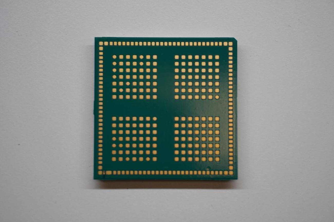
R7PMGZW1A1
May 01, 2026S2 EIC WiFi Chip
Equipment Class
DTS - Digital Transmission System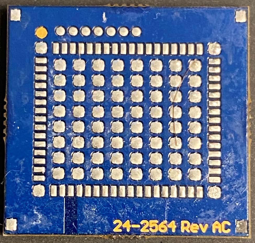
R7PNG0R1X8
Jul 18, 2022Electricity Meter Module
Equipment Class
DSS - Part 15 Spread Spectrum Transmitter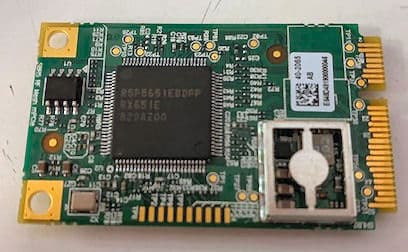
R7PNG0R1S5
Aug 19, 2020Series 5 mPCIe Module
Equipment Class
DSS - Part 15 Spread Spectrum Transmitter
R7PEG1R1S7
May 20, 2020LTE-M Cellular Communication Module
Equipment Class
DTS - Digital Transmission System
R7PNG0R1S6
Jan 28, 2020Comms Host Module
Equipment Class
DTS - Digital Transmission System