R7PFTAR2S1Communications Adapter
Landis+Gyr Technology, Inc.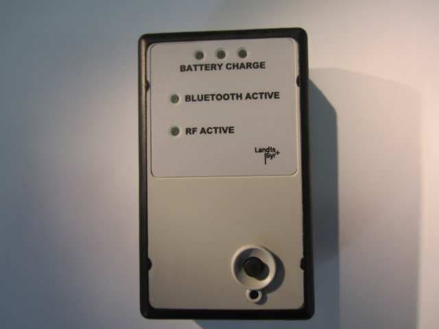
Click to zoom
Application Details
- Equipment Class
- DXT - Part 15 Low Power Transceiver, Rx Verified
- Date of Grant
- Jul 08, 2015
- Application Purpose
- Original Equipment
- Date of Application
- Jul 08, 2015
- Equipment Note
- Communications Adapter
- Frequency Range
- 902.30000000 - 927.50000000
- Company
- Landis+Gyr Technology, Inc.
- Country
- United States
Documents & Files
Document Text
Text extracted from the exhibit documents filed with the FCC. Open a document above to read the original.
Users Manual
5015 B.U. Bowman Drive Buford, GA 30518 USA Voice: 770-831-8048 Fax: 770-831-8598 Certification Exhibit FCC ID: R7PFTAR2S1 IC: 5294A-FTAR1S1 FCC Rule Part: 15.247, 15.249 IC Radio Standards Specification: RSS-210, RSS-247 ACS Project Number: 15-0159 Manufacturer: Landis+Gyr Technology, Inc. Model: Communications Adapter LANDIS+GYR CONFIDENTIAL INFORMATION Communications Adapter Quick Start Guide Publication: 98-1544 Rev AB Limitation on Warranties and Liability Information in this document is subject to change without notice. This manual or any part of it thereof may not be re- produced in any form unless permitted by contract or by written permission of Landis+Gyr. In no event will Landis+Gyr be liable for any incidental, indirect, special, or consequential damages (including lost prof- its) arising out of or relating to this publication or the information contained in it, even if Landis+Gyr has been advised, knew, or should have known of the possibility of such damages. © 2015 Landis+Gyr, Inc. All Rights Reserved C ommunications Adapter Quick Start Guide Publication: 98-1544 Rev AB Revision History Modification DateRevisionDescriptionAuthor 6/28/2015AB Released - Removed references to Field Tool Adapter Vicky Costello 6/4/2015AAReleasedVicky Costello © 2015 Landis+Gyr All rights reserved. Quick Start Guide98-1544 Rev AB3 Communications Adapter Quick Start Guide Product Description The Communications Adapter is a lightweight, compact device that is designed to ensure comfortable carrying and holding by the tool user. The adapter tool is capable of decoding one-way and two-way networks in a Gridstream environment. The device also incorporates a bluetooth module that provides communication to the tool device (tablet or laptop) and eliminates the need for serial cable connection. Two-way communication with the adapter provides the capability to transmit and receive data from AMI endpoints. One-way communication operates in a listener mode and provides ability to decode packets from AMR devices including gas and water modules. Figure 1. Communications Adapter Battery Level Indicator Bluetooth Connection Two-way and One-way Activity Power On and Off Button Module Reset Comm Adapter’s LAN ID Communications Adapter Quick Start GuideLandis+Gyr 498-1544 Rev ABQuick Start Guide NOTE: The LAN ID is a unique identifier for each endpoint. It always displays in hex. Landis+Gyr provides the LAN address. You cannot change the LAN ID of a radio. NOTE: The device was designed to operate at close range in order to minimize interference from unwanted readings while troubleshooting in the field. Landis+GyrCommunications Adapter Quick Start Guide Quick Start Guide98-1544 Rev AB5 The Communications Adapter kit includes a battery charger. Figure 2. Communications Adapter Kit Required Software For specific software and firmware questions, contact your Program/Project Manager directly or your Customer Account Representative. Communications Adapter Quick Start GuideLandis+Gyr 698-1544 Rev ABQuick Start Guide Getting Started To establish communication with the Communications Adapter, perform the following steps: 1.Press and hold the power button on the right-hand side to turn the adapter on. 2.Establish bluetooth communication with the tablet/laptop: A.From the Devices and Printers tab, locate or show the bluetooth devices. A list of bluetooth devices is displayed. B.Select Add a Device to choose the device that corresponds to Gridstream followed by the LAN ID printed on the back of the Communications Adapter. C.Enter PIN (0000) to add the device. D.Double-click the device once it is added to the Show Devices tab. E.Click the Hardware tab to obtain the COM port number that is used to set up communication with the software tools (COM port). Once the bluetooth is successfully paired/connected, the Communications Adapter’s Bluetooth Active LED will illuminate. General Usage The Communications Adapter provides field technicians with full mobility to perform field tool related activities at the site location of the endpoint. Once the tool software is activated, the Communications Adapter is ready to receive information from an electric, gas, or water meter. One- way communication is initiated by the swipe of a magnet to the unit being interrogated. Two-way communication occurs when the Communication Adapter requests information from the unit being interrogated. General Specification Communications Adapter Specifications Table 1. Product Specification ElementDescription Battery Life Normal use is 10 hours. The battery charge level is indicated on the front of the device. To view battery and charging status: - Green indicates the battery is fully charged. - Yellow indicates the battery is half charged. - Red indicates the battery is low and needs charging. RF Output Power10 milliwatts for close range connection One-Way Reception Range0 to 8 feet from water or gas meter LED 1 Green for One-Way and Two-Way (displayed on front of device) 1 Blue for Bluetooth active connection Landis+GyrCommunications Adapter Quick Start Guide Quick Start Guide98-1544 Rev AB7 FCC Compliance Information Compliance for Class B Devices This equipment has been tested and found to comply with the limits for a Class B digital device, pur- suant to Part 15 of the FCC Rules. These limits are designed to provide reasonable protection against harmful interference in a residential installation. This equipment generates, uses, and can radiate radio frequency energy and, if not installed and used in accordance with the Instructions, may cause harmful interference to radio communications. However, there is no guarantee that interference will not occur in a particular installation. If this equipment does cause harmful interference to radio or television re- ception, which can be determined by turning the equipment off and on, the user is encouraged to try to correct the interference by one or more of the following measures: •Reorient or relocate the rece…
Text truncated - open the document above for the full version.
Cover Letter(s)
30000 Mill Creek Avenue, Suite 100 | Alpharetta, GA 30022 Tel: +1 678 258 1637 | Fax: +1 678 258 1681 Date: June 23, 2015 Federal Communications Commission Equipment Authorization Branch 7435 Oakland Mills Rd. Columbia, MD 21046 Dear Sir or Madam: I hereby appoint Sam Wismer at Advanced Compliance Solutions, Inc. to act as our agent in the preparation of an application for equipment authorization of FCC ID: R7PFTAR2S1 to the FCC Rules and Regulations. I certify that all exhibits contained within this filing properly describe the device or system for which authorization is sought. I further certify that appropriate arrangements have been made to assure that production units of this equipment bearing the name and FCC IDENTIFIER listed in this application will continue to comply with the Commission's requirements. I further certify by signature below that no party (per 47 CFR 1.2002(b)) to the application is subject to a denial of Federal benefits, including FCC benefits, pursuant to Section 5301 of the Anti-Drug Abuse Act of 1988, 21 U.S.C. 853(a). This appointment also includes the authority to complete FCC Form 731 on our behalf and sign the application as an authorized agent. Sincerely, Name: Richard Timko Title: Quality Engineer
Cover Letter(s)
30000 Mill Creek Avenue, Suite 100 | Alpharetta, GA 30022 Tel: +1 678 258 1637 | Fax: +1 678 258 1681 CONFIDENTIALITY REQUEST Federal Communications CommissionDate: June 23, 2015 Equipment Authorization Branch 7435 Oakland Mills Road Columbia, MD 21046 Gentlemen: Landis+Gyr Technology, Inc. respectfully requests confidentiality of certain materials provided with the submission of the “Field Tool Adapter” under FCC ID: R7PFTAR2S1 in accordance with 47 CFR 0.457(d) and 47 CFR 0.459. The confidentiality request applies to the System Block Diagram, Schematics, and Theory of Operation contained in this filing and included in the following files. 15-0159 – System Block Diagram.pdf 15-0159 – Schematics.pdf 15-0159 – Theory of Operation.pdf The “Field Tool Adapter” has been developed at considerable effort and expense by Landis+Gyr Technology, Inc. These items are considered as Trade Secrets and therefore public access to the proprietary material could possibly result in duplication of equipment that could severely damage the company's business advantage. I appreciate your assistance in this matter. Sincerely, Name: Richard Timko Title: Quality Engineer
Cover Letter(s)
5015 B. U. Bowman Dr. Buford, GA 30518 June 23, 2015 ACS TCB 5015 B.U. Bowman Drive Buford, GA 30518 Re: FCC ID: R7PFTAR2S1 To Whom It May Concern: The following application is submitted on behalf of our client, Landis+Gyr Technology, Inc., for evaluation of their model Communications Adapter for certification under FCC Part 15.247 and 15.249. The Communications Adapter module is a battery powered “bridge” between a PC based application and the 900 MHz End Point Meter. The module contains a 900 MHz two way transceiver, a logarithmic Detector for 1 way Rx, Bluetooth transceiver and a lithium ion battery. It is contained in a belt mounted damage resistant plastic housing. The intent of the field tool is to be a close range device for trouble shooting Electric, Gas and water modules. The Bluetooth radio (FCC ID: ED9LMX9838, IC: 1520A-LMX9838) is a preapproved module enclosed in the Communications Adapter.This Bluetooth radio can transmit simultaneously with the 900 MHz transceiver; therefore, intermods were tested and were found to be compliant. The Communications Adapter operates utilizing a high power frequency hopping mode under FCC Part 15.247 and low power single channel mode under FCC Part 15.249. The Communications Adapter was tested in full to the requirements of the aforementioned rules and was found to be in compliance. Sincerely, Sam Wismer Vice President, Technology Advanced Compliance Solutions, Inc.
External Photos
5015 B.U. Bowman Drive Buford, GA 30518 USA Voice: 770-831-8048 Fax: 770-831-8598 Certification Exhibit FCC ID: R7PFTAR2S1 IC: 5294A-FTAR1S1 FCC Rule Part: 15.247, 15.249 IC Radio Standards Specification: RSS-210, RSS-247 ACS Project Number: 15-0159 Manufacturer: Landis+Gyr Technology, Inc. Model: Communications Adapter Model: Communications AdapterFCC ID: R7PFTAR2S1IC: 5294A-FTAR1S1 ACS Project: 15-0159Advanced Compliance SolutionsPage 2 Figure 1: External Photo Figure 2: External Photo Model: Communications AdapterFCC ID: R7PFTAR2S1IC: 5294A-FTAR1S1 ACS Project: 15-0159Advanced Compliance SolutionsPage 3 Figure 3: External Photo Figure 4: External Photo Model: Communications AdapterFCC ID: R7PFTAR2S1IC: 5294A-FTAR1S1 ACS Project: 15-0159Advanced Compliance SolutionsPage 4 Figure 5: External Photo
Internal Photos
5015 B.U. Bowman Drive Buford, GA 30518 USA Voice: 770-831-8048 Fax: 770-831-8598 Certification Exhibit FCC ID: R7PFTAR2S1 IC: 5294A-FTAR1S1 FCC Rule Part: 15.247, 15.249 IC Radio Standards Specification: RSS-210, RSS-247 ACS Project Number: 15-0159 Manufacturer: Landis+Gyr Technology, Inc. Model: Communications Adapter Model: Communications AdapterFCC ID: R7PFTAR2S1IC: 5294A-FTAR1S1 ACS Project: 15-0159Advanced Compliance SolutionsPage 2 Figure 1: Internal Photo Figure 2: Internal Photo Model: Communications AdapterFCC ID: R7PFTAR2S1IC: 5294A-FTAR1S1 ACS Project: 15-0159Advanced Compliance SolutionsPage 3 Figure 3: Internal Photo Figure 4: Internal Photo (without shields)
Test Report
5015 B.U. Bowman Drive Buford, GA 30518 USA Voice: 770-831-8048 Fax: 770-831-8598 Certification Test Report FCC ID: R7PFTAR2S1 IC: 5294A FTAR1S1 FCC Rule Part: 15.249 IC Radio Standards Specification: RSS 210 ACS Report Number: 15 0159.W06.1A Manufacturer: Landis+Gyr Technology, Inc. Model: Communications Adapter Test Begin Date: April 28, 2015 Test End Date: April 30, 2015 Report Issue Date: June 23, 2015 FOR THE SCOPE OF ACCREDITATION UNDER LAB Code 200612-0 This report must not be used by the client to claim product certification, approval, or endorsement by NVLAP, NIST, or any agency of the Federal Government. Reviewed by: Kirby Munroe Director, Wireless Certifications ACS, Inc. This test report shall not be reproduced except in full. This report may be reproduced in part with prior written consent of ACS, Inc. The results contained in this report are representative of the sample(s) submitted for evaluation. This report contains 20 pages 5015 B.U. Bowman Drive Buford, GA 30518 USA Voice: 770-831-8048 Fax: 770-831-8598 TABLE OF CONTENTS 1 GENERAL ............................................................................................................................................ 3 1.1 PURPOSE .......................................................................................................................................... 3 1.2 PRODUCT DESCRIPTION ................................................................................................................... 3 1.3 TEST METHODOLOGY AND CONSIDERATIONS ................................................................................. 4 2 TEST FACILITIES .............................................................................................................................. 5 2.1 LOCATION ....................................................................................................................................... 5 2.2 LABORATORY ACCREDITATIONS/RECOGNITIONS/CERTIFICATIONS ................................................ 5 2.3 RADIATED EMISSIONS TEST SITE DESCRIPTION .............................................................................. 6 2.3.1 Semi-Anechoic Chamber Test Site .......................................................................................... 6 2.3.2 Open Area Tests Site (OATS) ................................................................................................. 7 2.4 CONDUCTED EMISSIONS TEST SITE DESCRIPTION ........................................................................... 8 3 APPLICABLE STANDARD REFERENCES .................................................................................... 8 4 LIST OF TEST EQUIPMENT ............................................................................................................ 9 5 SUPPORT EQUIPMENT ...................................................................................................................10 6 EQUIPMENT UNDER TEST SETUP BLOCK DIAGRAM ..........................................................10 7 SUMMARY OF TESTS ......................................................................................................................11 7.1 ANTENNA REQUIREMENT – FCC 15.203 ........................................................................................11 7.2 POWER LINE CONDUCTED EMISSIONS – FCC 15.207; IC RSS-GEN 8.8 .........................................11 7.2.1 Measurement Procedure ........................................................................................................11 7.2.2 Measurement Results .............................................................................................................11 7.3 20DB / 99% BANDWIDTH – FCC 15.215; IC RSS-GEN 6.6.............................................................12 7.3.1 Measurement Procedure ........................................................................................................12 7.3.2 Measurement Results .............................................................................................................12 7.4 FUNDAMENTAL FIELD STRENGTH – FCC 15.249(A); IC RSS-210 A2.9(A) ....................................17 7.4.1 Measurement Procedure ........................................................................................................17 7.4.2 Measurement Results .............................................................................................................17 7.5 RADIATED SPURIOUS EMISSIONS – FCC 15.249(A)(D)(E); IC RSS-210 A2.9(A)(B) .......................18 7.5.1 Measurement Procedure ........................................................................................................18 7.5.2 Measurement Results .............................................................................................................18 7.5.3 Sample Calculation: ..............................................................................................................19 8 CONCLUSION ....................................................................................................................................20 Model: Communications Adapter FCC ID: R7PFTAR2S1 IC: 5294A FTAR1S1 ACS Report: 15 0159.W06.1A Advanced Compliance Solutions Page 3 1 GENERAL 1.1 Purpose The purpose of this report is to demonstrate compliance with Part 15 Subpart C of the FCC’s Code of Federal Regulations and Industry Canada’s Radio Standards Specification RSS-210 Certification. 1.2 Product description The Communications Adapter module is a battery powered “bridge” between a PC based application and the 900MHz End Point Meter. The module contains a 900MHz two-way transceiver, a logarithmic detector for one-way Rx, Bluetooth transceiver, and a lithium ion battery. It is contained in a belt mounted, damage resistant plastic housing. The intent of the field tool is to be a close range device for trouble shooting Electric, Gas, and Water modules. Technical Information: The model Communications Ad…
Text truncated - open the document above for the full version.
Test Setup Photos
5015 B.U. Bowman Drive Buford, GA 30518 USA Voice: 770-831-8048 Fax: 770-831-8598 Certification Exhibit FCC ID: R7PFTAR2S1 IC: 5294A-FTAR1S1 FCC Rule Part: 15.247, 15.249 IC Radio Standards Specification: RSS-210, RSS-247 ACS Project Number: 15-0159 Manufacturer: Landis+Gyr Technology, Inc. Model: Communications Adapter Model: Communications AdapterFCC ID: R7PFTAR2S1IC: 5294A-FTAR1S1 ACS Project: 15-0159Advanced Compliance SolutionsPage 2 Figure 1: Radiated Emissions Figure 2: Radiated Emissions Model: Communications AdapterFCC ID: R7PFTAR2S1IC: 5294A-FTAR1S1 ACS Project: 15-0159Advanced Compliance SolutionsPage 3 Figure 3: Conducted Emissions Figure 4: Conducted Emissions
Contact Information
Applicant
James L Stortz(Director of Hardware Engineering)
Test Firm
Advanced Compliance Solutions, Inc.Randy Abernathy
Technical Specifications
| # | Rule Parts | Frequency Range | Power Output |
|---|---|---|---|
| 1 | 15C | 902.3 MHz - 927.5 MHz | - |
Other Applications from Landis+Gyr Technology, Inc.
R7PMGZW1A1
May 01, 2026S2 EIC WiFi Chip
Equipment Class
DTS - Digital Transmission System
R7PMGBM2B1
Jan 08, 2024Series-6 Gen-2 MCM0
Equipment Class
DTS - Digital Transmission System
R7PNG0R1X8
Jul 18, 2022Electricity Meter Module
Equipment Class
DSS - Part 15 Spread Spectrum Transmitter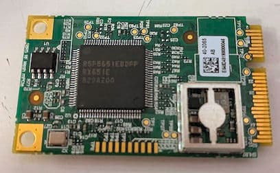
R7PNG0R1S5
Aug 19, 2020Series 5 mPCIe Module
Equipment Class
DSS - Part 15 Spread Spectrum Transmitter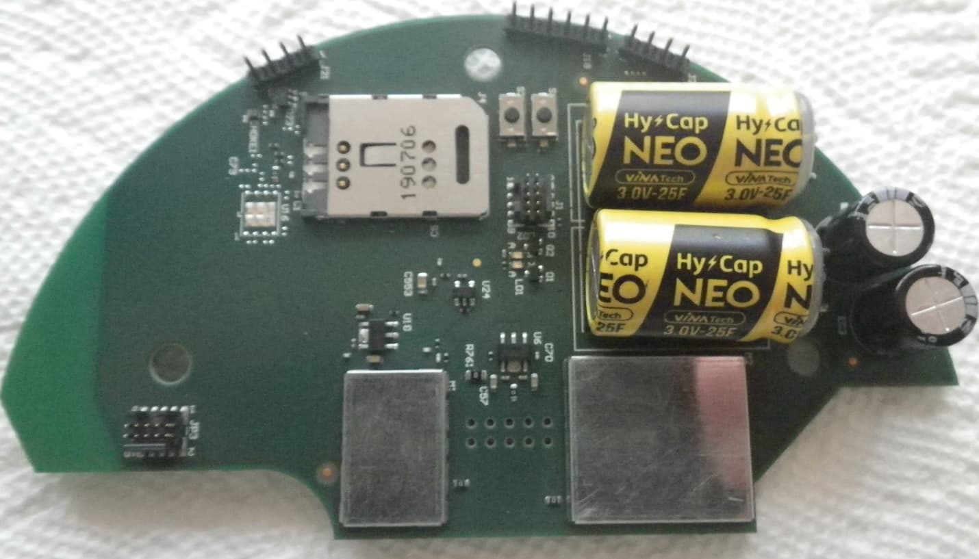
R7PEG1R1S7
May 20, 2020LTE-M Cellular Communication Module
Equipment Class
DTS - Digital Transmission System