R7RDMC23X6Surpass
VAST TECHNOLOGIES INC.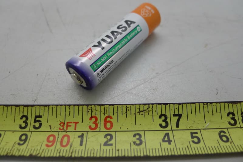
Click to zoom
Application Details
- Equipment Class
- DTS - Digital Transmission System
- Date of Grant
- Aug 03, 2015
- Application Purpose
- Original Equipment
- Date of Application
- Aug 03, 2015
- Equipment Note
- Surpass
- Frequency Range
- 2412.00000000 - 2462.00000000
- Company
- VAST TECHNOLOGIES INC.
- Country
- Taiwan
Documents & Files
Document Text
Text extracted from the exhibit documents filed with the FCC. Open a document above to read the original.
Users Manual
DMC-2316 Surpass Quick Guide Contents Parts of the Camera 1 Quick Guide USB Cable Power AdapterDMC Surpass AA Batteries 1 2 3 4 5 6 7 8 1 200X / 500X LENS (Optional) * 200X Fixed Focus Lens. * 500X Adjustable Focus Lens. 2 BATTERY SLOT 3 RESET 4 SNAPSHOT 5 FOCUS KNOB 6 LED ON/OFF 7 POWER ON/OFF 8 MICRO USB Getting Started 2 1. Using your smart device, visit the Apple App Store or Google Play to download the FREE Wi-Viewer app. 2. While the app is downloading, prepare Surpaβ by opening the battery door and inserting AA batteries in the battery compartment. (fig.1) NOTE: Follow the marking on the inside of the battery compartment to ensure the batteries are inserted correctly. (fig.1) (fig.3)(fig.4) 3. Slide the ON/OFF switcher to the ON position. The green LED will illuminate.(fig.2) *Red: Low battery. *Green: Power on and working. *Orange: Charging. NOTE: If LED indicator is illuminated red, the batteries are low on power and will need to be changed out. 4. Allow 30 seconds for the Wi-Fi network to boot up. 5. Go to your smart device's Wi-Fi setting menu and connector to the Surpaβ Wi-Fi network. (fig.6) NOTE: All Surpaβcameras create their own Wi-Fi network. Each is named "SURPAβ' follow by 5 random digits 6. To join the network, enter the default password: 12345678.(fig.7) NOTE: You can change the network's name and password in the "Setting" section of the Wi-Viewer app. for 3 seconds. 7. When connection to the network is successful, the green Wi-Fi signal LED (fig.3) will blink. 8. On your smart device, open the Wi-Viewer app. 9. If the live stream does not start automatically, touch the "ON" button.(fig.4) 10. Use AA battery *3 OR 5V/2A DC Adappter. (Please see the section on iOS/Android app operation) 3 5: Go back to main menu, and choose the Wi-viewer app. (fig.5)(fig.6)(fig.7) Touch the camera on button on the screen, you will see the live image from WiFi microscope. If you want to turn it off, touch the button again. ON/OFF: Touch the FREEZE button and the image will freeze. Touch the button again to go back to the live image. Freeze: ON OFF FREEZE Snapshot: Record/Stop Record: Play: Camera Setting: Wifi Setup:If you would like to change the default name of SSID/password, enter the alphanumeric within16, touch APPLY will store automatically and reboot. Image Setup:Set up the value of brightness/contrast/hue/saturation. Touch the Snapshot button to take a picture. Images can be found in the iPad/iphone pictures album. Record the real time video and stop record. Touch the Play icon to playback the saved videos. PLAY SNAP RECORD STOP Setting iOS app operation iOS App Function Key Listn 1. Go to the Settings Icon and choose WiFi setup.(fig.5) 2: Select Wi-Fi, and turn it on. 3. Select Wi-viewer.(fig.6) 4. Key in the password and then the connection will be established.(fig.7) Remark: The initial WiFi SSID is on the label inside of the Battery Cover The factory default password is 12345678. 4 Android App Operation Android App Function Key List 1. Go to the Settings Menu and choose WiFi setup.(fig.8) 2. Select Wi-viewer, and turn it on.(fig.9) 3. Key in the password and then the connection will be established. (fig.10) Remark: The initial WiFi SSID is on the label inside of the Battery Cover The factory default password is 12345678. 4. Go to the Home screen and choose ALL apps. 5. Choose Wi-viewer. Touch the Camera On button on the screen to view the live video image from WiFi camera. If you want to shut it down, touch the button again. ON/OFF: Record/Stop Record: Playback: Setting: Wifi Setup: If you would like to change the name of SSID/ password, please enter the alphanumeric within 16. Touch OK button, it will store automatically and reboot in the meantime. Reset SSID and Password: Set back the default value. Remark:The factory default value, please see as following, *WiFi SSID:Wi-Viewer *WiFi Password: 12345678 Snapshot: Touch the Snapshot button to take a picture. Saved images can be found in the pictures area on your android tablet or smartphone. Record the real time video and stop record. Playback the recorded videos. (fig.8)(fig.9)(fig.10) 5 Warning The battery must be charged 6 hours before rst using. FCC Statement This equipment has been tested and found to comply with the limits for a Class B digital device, pursuant to part 15 of the FCC Rules. These limits are designed to provide reasonable protection against harmful interference in a residential installation. This equipment generates, uses and can radiate radio frequency energy and, if not installed and used in accordance with the instructions, may cause harmful interference to radio communications. However, there is no guarantee that interference will not occur in a particular installation. If this equipment does cause harmful interference to radio or television reception, which can be determined by turning the equipment off and on, the user is encouraged to try to correct the interference by one or more of the following measures: - Reorient or relocate the receiving antenna. - Increase the separation between the equipment and receiver. - Connect the equipment into an outlet on a circuit different from that to which the receiver is connected. - Consult the dealer or an experienced radio/TV technician for help. FCC Radiation Exposure Statement This device complies with FCC radiation exposure limits set forth for an uncontrolled environment and it also complies with Part 15 of the FCC RF Rules. This equipment must be installed and operated in accordance with provided instructions and the antenna(s) used for this transmitter must be installed to provide a separation distance of at least 20 cm from all persons and must not be co-located or operating in conjunction with any other antenna or transmitter. End-users and installers must be provide with antenna installation instructions and consider removing the no-collocation statement. This device complies with Part 15 of the FCC Rules. Operation is subject to the following tw…
Text truncated - open the document above for the full version.
External Photos
Project No.: 1410008 Page 2 of 24 Project No.: 1410008 Page 3 of 24 Project No.: 1410008 Page 4 of 24 Project No.: 1410008 Page 5 of 24 Project No.: 1410008 Page 6 of 24
Internal Photos
Project No.: 1410008 Page 7 of 24 Project No.: 1410008 Page 8 of 24 Project No.: 1410008 Page 9 of 24 Project No.: 1410008 Page 10 of 24 Project No.: 1410008 Page 11 of 24 Project No.: 1410008 Page 12 of 24 Project No.: 1410008 Page 13 of 24 Project No.: 1410008 Page 14 of 24 Project No.: 1410008 Page 15 of 24 Project No.: 1410008 Page 16 of 24 Project No.: 1410008 Page 17 of 24 Project No.: 1410008 Page 18 of 24 Project No.: 1410008 Page 19 of 24 Project No.: 1410008 Page 20 of 24 Project No.: 1410008 Page 21 of 24 Project No.: 1410008 Page 22 of 24 Project No.: 1410008 Page 23 of 24 Project No.: 1410008 Page 24 of 24
RF Exposure Info
FCC RF EXPOSURE REPORT FCC ID: R7RDMC23X6 Project No. : 1410008 Equipment : Surpass Model : DMC-23X6 (X=0~9,A~Z) Applicant : VAST TECHNOLOGIES INC. Address : 7F, NO.80,SEC.1,KUANG FU RD.SANCHUNG,TAIPEI,TAIWAN,R.O.C. According: : FCC Guidelines for Human Exposure IEEE C95.1 BTL Inc. B1, No. 37, Lane 365, YangGuang St., NeiHu District 114, Taipei, Taiwan TEL : (0769) 8318-3000 FAX : (0769) 8319-6000 MPE CALCULATION METHOD: Calculation Method of RF Safety Distance: where: S = power density P = power input to the antenna G = power gain of the antenna in the direction of interest relative to an isotropic radiator R = distance to the center of radiation of the antenna Table for Filed Antenna Ant. Brand Model Name Antenna TypeConnector Gain(dBi) Note 1 NB0159-A100BX PCB AntennaN/A 2.2 2.4G TEST RESULTS EUT: Surpass Model Name : DMC-23X6 Temperature: 26 °C Relative Humidity: 56 % Test Voltage : AC 120V/60Hz Test Mode : TX B MODE /CH01, CH06, CH11 Antenna Gain (dBi) Antenna Gain (numeric) Peak Output Power (dBm) Peak Output Power (mW) Power Density (S) (mW/cm 2 ) Limit of Power Density (S) (mW/cm 2 ) Te s t Result 2.2 1.6596 17.05 50.6991 0.016747511 Complies 2.2 1.6596 17.58 57.2796 0.018921271 Complies 2.2 1.6596 17.65 58.2103 0.019228721 Complies EUT: Surpass Model Name : DMC-23X6 Temperature: 26 °C Relative Humidity: 56 % Test Voltage : AC 120V/60Hz Test Mode : TX G MODE /CH01, CH06, CH11 Antenna Gain (dBi) Antenna Gain (numeric) Peak Output Power (dBm) Peak Output Power (mW) Power Density (S) (mW/cm 2 ) Limit of Power Density (S) (mW/cm 2 ) Te s t Result 2.2 1.6596 19.64 92.0450 0.030405381 Complies 2.2 1.6596 20.02 100.4616 0.033185651 Complies 2.2 1.6596 19.78 95.0605 0.031401501 Complies EUT: Surpass Model Name : DMC-23X6 Temperature: 26 °C Relative Humidity: 56 % Test Voltage : AC 120V/60Hz Test Mode : TX N-20M MODE_ Total /CH01, CH06, CH11 Antenna Gain (dBi) Antenna Gain (numeric) Peak Output Power (dBm) Peak Output Power (mW) Power Density (S) (mW/cm 2 ) Limit of Power Density (S) (mW/cm 2 ) Te s t Result 2.2 1.6596 19.18 82.7942 0.027349561 Complies 2.2 1.6596 19.76 94.6237 0.031257221 Complies 2.2 1.6596 19.65 92.2571 0.030475471 Complies EUT: Surpass Model Name : DMC-23X6 Temperature: 26 °C Relative Humidity: 56 % Test Voltage : AC 120V/60Hz Test Mode : TX N-40M MODE_Total /CH03, CH06, CH09 Antenna Gain (dBi) Antenna Gain (numeric) Peak Output Power (dBm) Peak Output Power (mW) Power Density (S) (mW/cm 2 ) Limit of Power Density (S) (mW/cm 2 ) Te s t Result 2.2 1.6596 18.56 71.7794 0.023711031 Complies 2.2 1.6596 18.94 78.3430 0.025879171 Complies 2.2 1.6596 18.93 78.1628 0.025819651 Complies Note: the calculated distance is 20 cm.
Test Report
Report No.: BTL-FCCP-1-1410008 Page 1 of 123 FCC Radio Test Report FCC ID: R7RDMC23X6 This report concerns (check one): Original Grant Class II Change Project No. : 1410008 Equipment : Surpass Model Name : DMC-23X6 (X=0~9,A~Z) Applicant : VAST TECHNOLOGIES INC. Address : 7F, NO.80,SEC.1,KUANG FU RD.SANCHUNG,TAIPEI,TAIWAN,R.O.C. Date of Receipt : Oct. 07, 2014 Date of Test : Oct. 07, 2014 ~Jun. 17, 2015 Issued Date : Jun. 23, 2015 Tested by : BTL Inc. Testing Engineer : (Josh Lin) Technical Manager : (Jeff Yang) Authorized Signatory : (Andy Chiu) BTL INC. B1, No.37, Lane 365, Yang Guang St., Nei-Hu District, Taipei City 114, Taiwan. TEL: +886-2-2657-3299 FAX: +886-2-2657-3331 Report No.: BTL-FCCP-1-1410008 Page 2 of 123 Declaration BTL represents to the client that testing is done in accordance with standard procedures as applicable and that test instruments used has been calibrated with the standards traceable to National Measurement Laboratory (NML) of R.O.C, or National Institute of Standards and Technology (NIST) of U.S.A. BTL's reports apply only to the specific samples tested under conditions. It is manufacture’s responsibility to ensure that additional production units of this model are manufactured with the identical electrical and mechanical components. BTL shall have no liability for any declarations, inferences or generalizations drawn by the client or others from BTL issued reports. BTL’s report must not be used by the client to claim product certification, approval, or endorsement by NVLAP, NIST, or any agency of the Federal Government. This report is the confidential property of the client. As a mutual protection to the clients, the public and BTL-self, extracts from the test report shall not be reproduced except in full with BTL’s authorized written approval. BTL’s laboratory quality assurance procedures are in compliance with the ISO Guide 17025 requirements, and accredited by the conformity assessment authorities listed in this test report. Limitation For the use of the authority's logo is limited unless the Test Standard(s)/Scope(s)/Item(s) mentioned in this test report is (are) included in the conformity assessment authorities acceptance respective. Report No.: BTL-FCCP-1-1410008 Page 3 of 123 Table of Contents Page 1 . CERTIFICATION 6 2 . SUMMARY OF TEST RESULTS 7 2.1 TEST FACILITY 8 2.2 MEASUREMENT UNCERTAINTY 8 3 . GENERAL INFORMATION 9 3.1 GENERAL DESCRIPTION OF EUT 9 3.2 DESCRIPTION OF TEST MODES 11 3.3 TABLE OF PARAMETERS OF TEXT SOFTWARE SETTING 12 3.4 BLOCK DIAGRAM SHOWING THE CONFIGURATION OF SYSTEM TESTED 13 3.5 DESCRIPTION OF SUPPORT UNITS 13 4 . EMC EMISSION TEST 14 4.1 CONDUCTED EMISSION MEASUREMENT 14 4.1.1 POWER LINE CONDUCTED EMISSION LIMITS 14 4.1.2 TEST PROCEDURE 14 4.1.3 DEVIATION FROM TEST STANDARD 14 4.1.4 TEST SETUP 15 4.1.5 EUT OPERATING CONDITIONS 15 4.1.6 EUT TEST CONDITIONS 15 4.1.7 TEST RESULTS 15 4.2 RADIATED EMISSION MEASUREMENT 16 4.2.1 RADIATED EMISSION LIMITS 16 4.2.2 TEST PROCEDURE 17 4.2.3 DEVIATION FROM TEST STANDARD 17 4.2.4 TEST SETUP 17 4.2.5 EUT OPERATING CONDITIONS 18 4.2.6 EUT TEST CONDITIONS 18 4.2.7 TEST RESULTS (9KHZ TO 30MHZ) 19 4.2.8 TEST RESULTS (BETWEEN 30MHZ TO 1000 MHZ) 19 4.2.9 TEST RESULTS (ABOVE 1000 MHZ) 19 5 . BANDWIDTH TEST 20 5.1 APPLIED PROCEDURES 20 5.1.1 TEST PROCEDURE 20 5.1.2 DEVIATION FROM STANDARD 20 5.1.3 TEST SETUP 20 5.1.4 EUT OPERATION CONDITIONS 20 5.1.5 EUT TEST CONDITIONS 20 5.1.6 TEST RESULTS 20 Report No.: BTL-FCCP-1-1410008 Page 4 of 123 Table of Contents Page 6 . MAXIMUM PEAK CONDUCTED OUTPUT POWER TEST 21 6.1 APPLIED PROCEDURES / LIMIT 21 6.1.1 TEST PROCEDURE 21 6.1.2 DEVIATION FROM STANDARD 21 6.1.3 TEST SETUP 21 6.1.4 EUT OPERATION CONDITIONS 21 6.1.5 EUT TEST CONDITIONS 21 6.1.6 TEST RESULTS 21 7 . ANTENNA CONDUCTED SPURIOUS EMISSION 22 7.1 APPLIED PROCEDURES / LIMIT 22 7.1.1 TEST PROCEDURE 22 7.1.2 DEVIATION FROM STANDARD 22 7.1.3 TEST SETUP 22 7.1.4 EUT OPERATION CONDITIONS 22 7.1.5 EUT TEST CONDITIONS 22 7.1.6 TEST RESULTS 22 8 . POWER SPECTRAL DENSITY TEST 23 8.1 APPLIED PROCEDURES / LIMIT 23 8.1.1 TEST PROCEDURE 23 8.1.2 DEVIATION FROM STANDARD 23 8.1.3 TEST SETUP 23 8.1.4 EUT OPERATION CONDITIONS 23 8.1.5 EUT TEST CONDITIONS 23 8.1.6 TEST RESULTS 23 9 . MEASUREMENT INSTRUMENTS LIST 24 10 . EUT TEST PHOTO 26 ATTACHMENT A - CONDUCTED EMISSION 30 ATTACHMENT B - RADIATED EMISSION (9KHZ TO 30MHZ) 33 ATTACHMENT C - RADIATED EMISSION (30MHZ TO 1000MHZ) 35 ATTACHMENT D - RADIATED EMISSION (ABOVE 1000MHZ) 38 ATTACHMENT E - BANDWIDTH 87 ATTACHMENT F – MAXIMUM PEAK CONDUCTED OUTPUT POWER 96 ATTACHMENT G - ANTENNA CONDUCTED SPURIOUS EMISSION 98 ATTACHMENT H - POWER SPECTRAL DENSITY 115 Report No.: BTL-FCCP-1-1410008 Page 5 of 123 REPORT ISSUED HISTORY Issued No. Description Issued Date BTL-FCCP-1-1410008 Original Issue. Jun. 23, 2015 Report No.: BTL-FCCP-1-1410008 Page 6 of 123 1. CERTIFICATION Equipment : Surpass Brand Name : VAST Model Name : DMC-23X6 (X=0~9,A~Z) Applicant : VAST TECHNOLOGIES INC. Manufacturer : VAST TECHNOLOGIES INC. Address : 7F, NO.80,SEC.1,KUANG FU RD.SANCHUNG,TAIPEI,TAIWAN,R.O.C. Date of Test : Oct. 07, 2014 ~Jun. 17, 2015 Test Sample : ENGINEERING SAMPLE Standard(s) : FCC Part15, Subpart C: 2014 (15.247) / ANSI C63.4-2009 The above equipment has been tested and found compliance with the requirement of the relative standards by BTL Inc. The test data, data evaluation, and equipment configuration contained in our test report (Ref No. BTL-FCCP-1-1410008 ) were obtained utilizing the test procedures, test instruments, test sites that has been accredited by the Authority of TAF according to the ISO-17025 quality assessment standard and technical standard(s). Report No.: BTL-FCCP-1-1410008 Page 7 of 123 2. SUMMARY OF TEST RESULTS Test procedures according to the technical standard(s): Applied Standard(s): FCC Part15 (15.247) , Subpart C: 2014 Standard(s) Section Test Item Judgment Remark FCC 15.207 Conducted Emission PASS 15.247(d) Antenna conducted Spurious Emission PASS 15.247(…
Text truncated - open the document above for the full version.
Test Setup Photos
Report No.: BTL-FCCP-1-1410008 Page 26 of 123 10. EUT TEST PHOTO Conducted Measurement Photos Report No.: BTL-FCCP-1-1410008 Page 27 of 123 Radiated Measurement Photos 9KHz to 30MHz Report No.: BTL-FCCP-1-1410008 Page 28 of 123 Radiated Measurement Photos 30MHz to 1000MHz Report No.: BTL-FCCP-1-1410008 Page 29 of 123 Radiated Measurement Photos Above 1000MHz
Contact Information
Applicant
Bert Chang
Technical Contact
Non-Technical Contact
BTL Inc.Cathy Wang
[email protected]86-769-83183000
Test Firm
BTL Inc.Andy Chiu
Technical Specifications
| # | Rule Parts | Frequency Range | Power Output |
|---|---|---|---|
| 1 | 15C | 2.41 GHz - 2.46 GHz | 100.00 mW |
Other Applications from VAST TECHNOLOGIES INC.
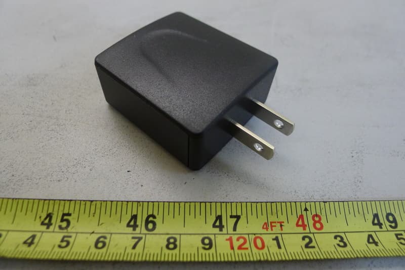
R7RDWS1113
Aug 24, 2014WIFI STATION
Equipment Class
DTS - Digital Transmission System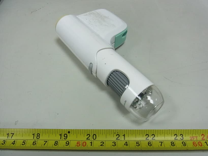
R7RDMC2313
Dec 27, 2012WiFi Microscope
Equipment Class
DTS - Digital Transmission System