R7TAMB2561Low Power Transceiver
Wuerth Elektronik eiSos GmbH & Co KG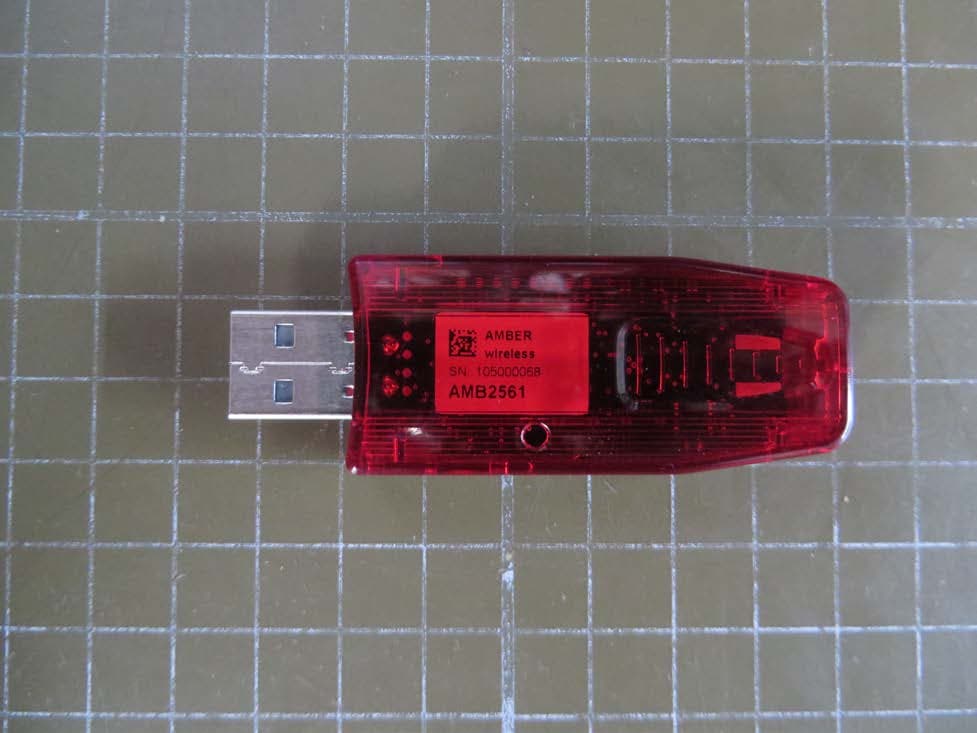
Click to zoom
Application Details
- Equipment Class
- DXT - Part 15 Low Power Transceiver, Rx Verified
- Date of Grant
- Mar 19, 2015
- Application Purpose
- Original Equipment
- Date of Application
- Mar 17, 2015
- Equipment Note
- Low Power Transceiver
- Frequency Range
- 2400.70000000 - 2482.75000000
- Country
- Germany
Documents & Files
Document Text
Text extracted from the exhibit documents filed with the FCC. Open a document above to read the original.
Users Manual
Manual AMB2561 Version 1.1 AMBER wireless GmbH Phone +49.651.993.550 Email [email protected] Internet www.amber-wireless.de AMB2561_MA_V1_0 Page 2 of 11 Date: 03/2014 Table of Contents 1 Startup „Step-by-step“ ............................................................................................... 3 2 Using the USB-Stick with a terminal program .......................................................... 4 2.1 Example Terminal.exe ..................................................................................................... 4 3 Using the configuration software “ACC” .................................................................. 5 4 Disconnecting the DTR-Signal .................................................................................. 6 5 References .................................................................................................................. 7 6 Regulatory compliance information .......................................................................... 8 6.1 Important notice ............................................................................................................... 8 6.2 Declaration of conformity ........................................... Fehler! Textmarke nicht definiert. 7 Important Information .............................................................................................. 11 7.1 Exclusion of Liability ....................................................................................................... 11 7.2 Trademarks .................................................................................................................... 11 7.3 Usage Restriction ........................................................................................................... 11 AMB2561_MA_V1_0 Page 3 of 11 Date: 03/2014 1 Startup „Step-by-step“ 1. Driver Installation The first step of the startup procedure of the USB Stick is to install the driver for the virtual COM Port. Therefor the installation zip archive for the USB IC, namely the FT231XQ, first has to be downloaded from the manufacturer website (FTDI [5]). Afterwards the extraction and installation according to the displayed guidelines takes place until the installation has successfully finished. 2. Plug in the USB-stick Now the USB stick can be connected to a free USB slot on the pc, the red power LED lights up. Windows automatically identifies the connected device. A Windows routine for the allocation of the driver starts automatically. 3. Serial Port The driver now creates a virtual serial port on your system with the following default port settings: 38400 Baud, 8 data bits, no parity and 1 stop bit. 4. Using the stick Now the USB-Stick can be accessed via serial port as described in the AMB2520 manual [1]. 5. Demo program [2] By the use two USB Sticks with the same RF settings (e.g. in default channel 79 / 2440,0MHz) and the demo program, it is possible to conduct a range measurement. The Demo program uses the default settings of 38400 baud 8n1 on the COM interface. For the range measurement the demo program has to be started for each USB stick respectively (e.g. the first stick on a PC and the second Stick on a Laptop). The corresponding COM-Port has to be opened. If the sticks are operated in close proximity of each other it may occur that the receiver amplifiers are overdriven which could result in failure of communication. By clicking on the button “Toggle Mode” both modules are set into “Command Mode”. To start the signal strength measurement click on “Start RSSI test” on one of the demo programs. If the progress bar under the button “Start RSSI test” makes no further progress you can restart the measurement by a renewed click on “Start RSSI test”. The stick has an internal LED to signal incoming data. AMB2561_MA_V1_0 Page 4 of 11 Date: 03/2014 The detailed description of the configuration possibilities, operating modes, commands, etc. can be found in the manual [1]. A “high” level on the DTR line holds the module in reset state. Some terminal programs automatically set the DTR line to “high” when opening the COM port, which prevents normal operation of the stick. The signal level on the DTR line has to be set to “low”. 2 Using the USB-Stick with a terminal program Since not all terminal programs offer the possibility to configure the DTR line, it has to be mentioned that “Terminal.exe” is a program which does offer this necessary functionality. It can be downloaded free of charge from [3]. 2.1 Example Terminal.exe The program can be started directly after haven been downloaded and extracted onto your PC, without any further installation. In the upper left corner you can select the COM port (between COM1 and COM20). If the stick is assigned to a higher port number by Windows, you may follow the instructions under [4] to release COM ports that are not in use. Thereafter the remaining settings can be selected (38400 Baud, 8n1, no handshaking), and the COM port may be opened by clicking the “Connect” button. By clicking on the DTR LED (see red arrow) it is possible to switch the DTR line to “high” or to “low” (LED is gray). With DTR set to “low” the stick is now able to transmit the data which is entered in the “send” field at the bottom. The received data is displayed in the “Receive” field above. AMB2561_MA_V1_0 Page 5 of 11 Date: 03/2014 Terminal program 3 Using the configuration software “ACC” The configuration software AMBER Config Center, ACC, is available for registered users [6]. The connection process is shown below: 1. Connect the USB-Stick to a free slot on your PC. 2. Determine the associated COM-Port in the device manager. 3. Start the ACC software and enter the correct COM-Port. 4. Click on “Connect”. ... AMB2561_MA_V1_0 Page 6 of 11 Date: 03/2014 5. Push “reset” button. 6. Now the module settings may be read and edited. 4 Disconnecting the DTR-Signal If the reset functionality via the virtual COM port is not required or it causes …
Text truncated - open the document above for the full version.
External Photos
Date: 2014-03-07 Page 1 of 7 Vers. no. 1.14 m. dudde hochfrequenz-technik Rottland 5a D-51429 Bergisch Gladbach/ Germany Tel: +49 2207-96890 Fax +49 2207-968920 Annex no. 1 External Photographs Date: 2014-03-07 Page 2 of 7 Vers. no. 1.14 m. dudde hochfrequenz-technik Rottland 5a D-51429 Bergisch Gladbach/ Germany Tel: +49 2207-96890 Fax +49 2207-968920 Photographs of the test equipment (EUT) – AMB 2561 - Upper side of unit Date: 2014-03-07 Page 3 of 7 Vers. no. 1.14 m. dudde hochfrequenz-technik Rottland 5a D-51429 Bergisch Gladbach/ Germany Tel: +49 2207-96890 Fax +49 2207-968920 Photographs of the test equipment (EUT) – AMB 2561 - Lower side of unit Date: 2014-03-07 Page 4 of 7 Vers. no. 1.14 m. dudde hochfrequenz-technik Rottland 5a D-51429 Bergisch Gladbach/ Germany Tel: +49 2207-96890 Fax +49 2207-968920 Photographs of the test equipment (EUT) – AMB 2561 – Side 1 view of unit Date: 2014-03-07 Page 5 of 7 Vers. no. 1.14 m. dudde hochfrequenz-technik Rottland 5a D-51429 Bergisch Gladbach/ Germany Tel: +49 2207-96890 Fax +49 2207-968920 Photographs of the test equipment (EUT) – AMB 2561 – Side 2 view of unit Date: 2014-03-07 Page 6 of 7 Vers. no. 1.14 m. dudde hochfrequenz-technik Rottland 5a D-51429 Bergisch Gladbach/ Germany Tel: +49 2207-96890 Fax +49 2207-968920 Photographs of the test equipment (EUT) – AMB 2561 – Top view of unit Date: 2014-03-07 Page 7 of 7 Vers. no. 1.14 m. dudde hochfrequenz-technik Rottland 5a D-51429 Bergisch Gladbach/ Germany Tel: +49 2207-96890 Fax +49 2207-968920 Photographs of the test equipment (EUT) – AMB 2561 – Bottom view of unit
ID Label/Location Info
Date: 2014-03-07 Page 1 of 3 Vers. no. 1.14 m. dudde hochfrequenz-technik Rottland 5a D-51429 Bergisch Gladbach/ Germany Tel: +49 2207-96890 Fax +49 2207-968920 Annex no. 4 Label Sample Date: 2014-03-07 Page 2 of 3 Vers. no. 1.14 m. dudde hochfrequenz-technik Rottland 5a D-51429 Bergisch Gladbach/ Germany Tel: +49 2207-96890 Fax +49 2207-968920 Label Sample of the test equipment (EUT) – AMB 2561 Date: 2014-03-07 Page 3 of 3 Vers. no. 1.14 m. dudde hochfrequenz-technik Rottland 5a D-51429 Bergisch Gladbach/ Germany Tel: +49 2207-96890 Fax +49 2207-968920 Label Location on Lower side of the test equipment (EUT) – AMB 2561
Internal Photos
Date: 2014-03-07 Page 1 of 3 Vers. no. 1.14 m. dudde hochfrequenz-technik Rottland 5a D-51429 Bergisch Gladbach/ Germany Tel: +49 2207-96890 Fax +49 2207-968920 Annex no. 2 Internal Photographs Date: 2014-03-07 Page 2 of 3 Vers. no. 1.14 m. dudde hochfrequenz-technik Rottland 5a D-51429 Bergisch Gladbach/ Germany Tel: +49 2207-96890 Fax +49 2207-968920 Photographs of the test equipment (EUT) – AMB 2561 - Upper side of AMB2561 PCB Date: 2014-03-07 Page 3 of 3 Vers. no. 1.14 m. dudde hochfrequenz-technik Rottland 5a D-51429 Bergisch Gladbach/ Germany Tel: +49 2207-96890 Fax +49 2207-968920 Photographs of the test equipment (EUT) – AMB 2561 - Lower side of AMB2561 PCB
Test Report
Date: 2014-03-07 Page 1 of 4 Vers. no. 1.14 m. dudde hochfrequenz-technik Rottland 5a D-51429 Bergisch Gladbach/ Germany Tel: +49 2207-96890 Fax +49 2207-968920 Annex no. 3 Occupied Bandwidth Plot Date: 2014-03-07 Page 2 of 4 Vers. no. 1.14 m. dudde hochfrequenz-technik Rottland 5a D-51429 Bergisch Gladbach/ Germany Tel: +49 2207-96890 Fax +49 2207-968920 20 dB bandwidth Date: 2014-03-07 Page 3 of 4 Vers. no. 1.14 m. dudde hochfrequenz-technik Rottland 5a D-51429 Bergisch Gladbach/ Germany Tel: +49 2207-96890 Fax +49 2207-968920 99 % dB bandwidth Date: 2014-03-07 Page 4 of 4 Vers. no. 1.14 m. dudde hochfrequenz-technik Rottland 5a D-51429 Bergisch Gladbach/ Germany Tel: +49 2207-96890 Fax +49 2207-968920 Out of band emissions
Test Report
Test report no. 15009804 Page 1 of 29 EUT: AMB2561 FCC ID: R7TAMB2561 FCC Title 47 CFR Part 15 C Date of issue: 2015-03-12 Date: 2015-03-11 Vers. no. 1.15 m. dudde hochfrequenz-technik Rottland 5a D-51429 Bergisch Gladbach/ Germany Tel: +49 2207-96890 Fax +49 2207-968920 Test Report acc. to FCC Title 47 CFR Part 15 relating to AMBER Wireless GmbH AMB2561 Title 47 - Telecommunication Part 15 - Radio Frequency Devices Subpart C – Intentional Radiators Measurement Procedure: ANSI C63.4-2009 Test report no. 15009804 Page 2 of 29 EUT: AMB2561 FCC ID: R7TAMB2561 FCC Title 47 CFR Part 15 C Date of issue: 2015-03-12 Date: 2015-03-11 Vers. no. 1.15 m. dudde hochfrequenz-technik Rottland 5a D-51429 Bergisch Gladbach/ Germany Tel: +49 2207-96890 Fax +49 2207-968920 MANUFACTURER Manufacturer name AMBER Wireless GmbH Manufacturer’s grantee code R7T Manufacturer’s address Rudi-Schillings-Str.31, 54296 Trier, Germany Phone +49 (0) 651 99355 0 Fax +49 (0) 651 99355 69 Email [email protected] References Mrs. Gudrun Eckhardt TESTING LABORATORY Test engineer Mr. Ralf Trepper Testing laboratory name m. dudde hochfrequenz-technik Testing laboratory address Rottland 5a, 51429 Bergisch Gladbach, Germany Phone +49 2207 96890 Fax +49 2207 968920 Email [email protected] RELEVANT STANDARD Title 47 - Telecommunication Part 15 - Radio Frequency Devices Subpart Subpart C – Intentional Radiators Measurement procedure ANSI C63.4-2009 EQUIPMENT UNDER TEST (EUT) Equipment category 2.4 GHz USB-RF Adapter / Short Range Device Trade name --- Type designation AMB2561 Serial no. 105.000149 /105.000012 / 105.000068 Variants --- Test report no. 15009804 Page 3 of 29 EUT: AMB2561 FCC ID: R7TAMB2561 FCC Title 47 CFR Part 15 C Date of issue: 2015-03-12 Date: 2015-03-11 Vers. no. 1.15 m. dudde hochfrequenz-technik Rottland 5a D-51429 Bergisch Gladbach/ Germany Tel: +49 2207-96890 Fax +49 2207-968920 1. Test results Clause Requirements headline Test result Page number 8.1 Antenna requirement Pass Fail N.t.* 9 8.2 Conducted limits Pass Fail N.t.* 10 - 12 8.3 Restricted bands of operation Pass Fail N.t.* 13 - 14 8.4 Radiated emission limits, general requirements Pass Fail N.t.* 15 - 20 8.5 Fundamental frequencies / Field strength limits Pass Fail N.t.* 21 - 24 8.6 Bandwidth Pass Fail N.t.* 25 * Not tested The equipment passed all the conducted tests Yes No Signature Name Mr. Ralf Trepper Mr. Manfried Dudde Designation Technician Laboratory-Manager Date of issue 2015-03-12 2015-03-12 Test report no. 15009804 Page 4 of 29 EUT: AMB2561 FCC ID: R7TAMB2561 FCC Title 47 CFR Part 15 C Date of issue: 2015-03-12 Date: 2015-03-11 Vers. no. 1.15 m. dudde hochfrequenz-technik Rottland 5a D-51429 Bergisch Gladbach/ Germany Tel: +49 2207-96890 Fax +49 2207-968920 Table of contents 1. Test results ........................................................................................................................................................ 3 2. Introduction ...................................................................................................................................................... 5 3. Testing laboratory ............................................................................................................................................ 5 4. Applicant .......................................................................................................................................................... 6 5. Product and product documentation ................................................................................................................ 6 6. Conclusions, observations and comments ....................................................................................................... 7 7. Operational description ..................................................................................................................................... 8 8. Compliance assessment .................................................................................................................................... 9 8.1 Antenna requirement ...................................................................................................................................... 9 8.1.2 Result .................................................................................................................................................... 9 8.2 Conducted limits ............................................................................................................................................ 10 8.2.1 Regulation ............................................................................................................................................. 10 8.2.2 Test procedures ..................................................................................................................................... 11 8.2.3 Result .................................................................................................................................................... 11 8.3 Restricted bands of operation .......................................................................................................................... 13 8.3.1 Regulation ............................................................................................................................................. 13 8.3.2 Result .................................................................................................................................................... 15 8.4 Radiated emission limits, general requirements ............................................................................................ 16 8.4.1 Regulation ............................................................................................................................................. 16 8.4.2 Test procedure ......................................................................................................................…
Text truncated - open the document above for the full version.
Test Setup Photos
Date: 2014-03-07 Page 1 of 6 Vers. no. 1.14 m. dudde hochfrequenz-technik Rottland 5a D-51429 Bergisch Gladbach/ Germany Tel: +49 2207-96890 Fax +49 2207-968920 Annex no. 6 Test Setup Photographs Date: 2014-03-07 Page 2 of 6 Vers. no. 1.14 m. dudde hochfrequenz-technik Rottland 5a D-51429 Bergisch Gladbach/ Germany Tel: +49 2207-96890 Fax +49 2207-968920 Radiated emissions Up to 1 GHz (horizontally) Up to 1 GHz (vertically) Date: 2014-03-07 Page 3 of 6 Vers. no. 1.14 m. dudde hochfrequenz-technik Rottland 5a D-51429 Bergisch Gladbach/ Germany Tel: +49 2207-96890 Fax +49 2207-968920 Radiated emissions Up to 1 GHz (horizontally) Up to 1 GHz (vertically) Date: 2014-03-07 Page 4 of 6 Vers. no. 1.14 m. dudde hochfrequenz-technik Rottland 5a D-51429 Bergisch Gladbach/ Germany Tel: +49 2207-96890 Fax +49 2207-968920 Radiated emissions Above 1 GHz (horizontally) Above 1 GHz (vertically) Date: 2014-03-07 Page 5 of 6 Vers. no. 1.14 m. dudde hochfrequenz-technik Rottland 5a D-51429 Bergisch Gladbach/ Germany Tel: +49 2207-96890 Fax +49 2207-968920 AC power line conducted emissions Laptop on standalone basis Date: 2014-03-07 Page 6 of 6 Vers. no. 1.14 m. dudde hochfrequenz-technik Rottland 5a D-51429 Bergisch Gladbach/ Germany Tel: +49 2207-96890 Fax +49 2207-968920 AC power line conducted emissions Laptop with AMB2561
Contact Information
Applicant
Gudrun Eckhardt(Manager)
Technical Contact
AMBER wireless GmbHGudrun Eckhardt
[email protected]49 (0) 651 99355 0
Rudi-Schillings-Str.31, · Germany
Non-Technical Contact
AMBER wireless GmbHHeinz Brych
[email protected]49 (0) 651 99355 0
Test Firm
m. dudde hochfrequenz-technikManfred Dudde
Technical Specifications
| # | Rule Parts | Frequency Range | Power Output |
|---|---|---|---|
| 1 | 15C | 2.40 GHz - 2.48 GHz | - |
Other Applications from Wuerth Elektronik eiSos GmbH & Co KG
R7T1501113
Jun 02, 2026LTE-M / NB-IoT Cellular Module
Equipment Class
PCB - PCS Licensed TransmitterR7T2101102
Sep 04, 2025Bluetooth LE radio module
Equipment Class
DTS - Digital Transmission System
R7T2001102
Sep 04, 2024A Bluetooth module.
Equipment Class
DTS - Digital Transmission System
R7TOPC1600
Oct 25, 2007Bluetooth Transceiver Module
Equipment Class
DXX - Part 15 Low Power Communication Device Transmitter
R7TAMB2300
Apr 10, 2007Bluetooth module BlueNiceCom IV
Equipment Class
DXX - Part 15 Low Power Communication Device Transmitter