R7TOPC1600Bluetooth Transceiver Module
Wuerth Elektronik eiSos GmbH & Co KG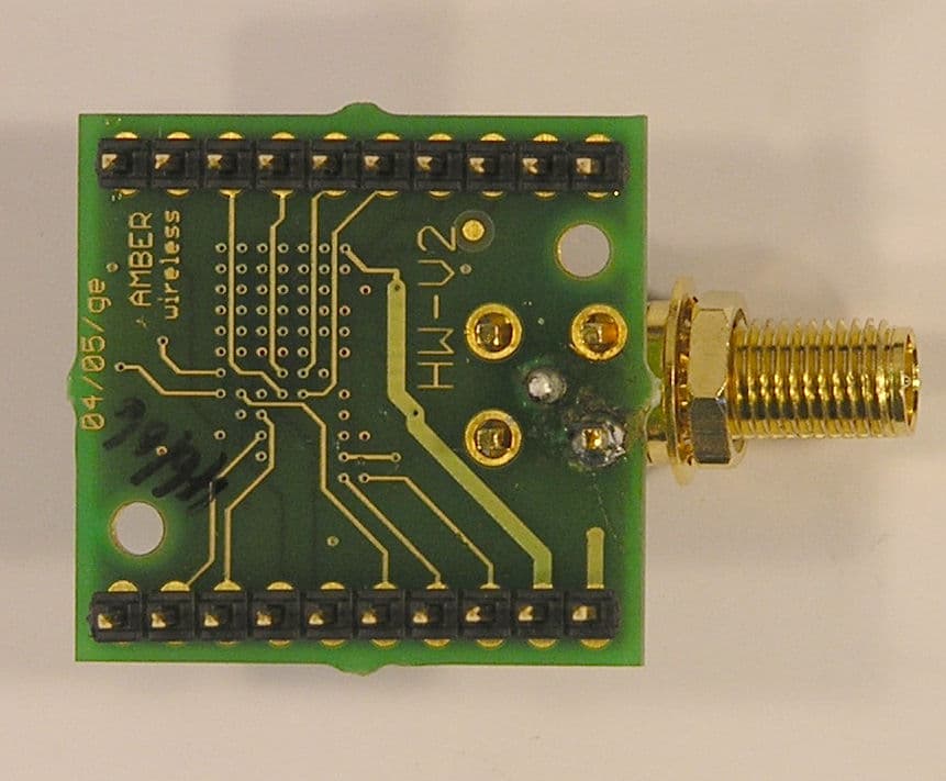
Click to zoom
Application Details
- Equipment Class
- DXX - Part 15 Low Power Communication Device Transmitter
- Date of Grant
- Oct 25, 2007
- Application Purpose
- Original Equipment
- Date of Application
- Oct 25, 2007
- Equipment Note
- Bluetooth Transceiver Module
- Frequency Range
- 2402.00000000 - 2480.00000000
- Country
- Germany
Documents & Files
Document Text
Text extracted from the exhibit documents filed with the FCC. Open a document above to read the original.
Block Diagram
Annex No.7 Page 1 of 1 Block Diagram : OPC1600 (BlueNiceCom2)
Cover Letter(s)
m. dudde hochfrequenz-technik Rottland 5a, D-51429 Bergisch-Gladbach DIN EN ISO/IEC 17025 zertifiziert Akkreditiertes Testhaus - Reg.-Nr.: TTI-P-G128/96 Tel. : +49 22 07 - 96 89 - 0 Fax : +49 22 07 - 96 89 - 20 email: [email protected] www.dudde.com Date 2007-09-19 Federal Communications Commission 7435 Oakland Mills Road Columbia, MD 21046 Subject: Request for confidentiality FCC ID:R7TOPC1600) Gentlemen: This letter is to comply with Section 0.457(d)(1)(ii) and Section 0.459 pertaining to confidential material. Amber wireless OPC1600, Albin-Köbis-Strasse 18, D-51147, Köln, Germany would like the following documents regarding this submission for FCC ID: R7TOPC1600 to be kept confidential. Amber wireless OPC1600 1. Page 2 to 3 of Annex no. 8 document “Schematics” The above material contains trade secret or technical data, which would customarily be guarded from competitors. We do not want these documents to be accessible to the general public. Sincerely, m. dudde hochfrequenz-technik Manfred Dudde
Cover Letter(s)
m. dudde hochfrequenz-technik Rottland 5a, D-51429 Bergisch-Gladbach DIN EN ISO/IEC 17025 zertifiziert Akkreditiertes Testhaus - Reg.-Nr.: DAT-P-G225/96-02 Tel. : +49 22 07 - 96 89 - 0 Fax : +49 22 07 - 96 89 - 20 email: [email protected] www.dudde.com Page 1 of 2 Date: 2007-09-26 Subject: Limited Modular Approval request To: FCC TCB Herewith we would like to apply for "Limited Modular Approval" for the following device: Applicant/manufacturer: Amber Wireless GmbH Module name: OPC1600 FCC ID: R7TOPC1600 This device is subject of this FCC application package. Justification for our request is summarized below: 1. RF shielding The module has no RF shielding and was tested without any housing. We apply for a Limited Modular Approval, constrained to be sold to Sasse Elektronik GmbH only. The product is designed for being built into user interfaces of industrial or medical equipment. There is a user manual available which instructs Sasse Elektronik GmbH how to implement the modules and use them in a way that compliance of the product is always ensured. 2. Data Inputs The module has buffered data input via SPI-bus to the onboard μ-controller (see schematic diagrams). The user has no direct access to the registers of the integrated RF module and can only set a few parameters to control frequency channel, output RF power and bit rate of the device. 3. Power supply regulation The module has its own voltage regulator integrated (see schematic diagrams). 4. Antenna The transceiver module OPC1600 may be used with one of the following antennas: - Laird Technologies WCR2400-SMRP - EAD BT-Blade™ FBT35009-RS-1K5 with 1.5m-RG174-Cable (see test report) The antenna coupler is a non-standard inverse SMA-socket. The user manual gives instruction to the antenna issue. 5. Stand alone tested The EUT has been tested in stand-alone configuration without housing or shielding. The module was connected to the serial port of a standard PC with an evaluation board. The unshielded module was found to conform to FCC Part 15 requirements (see test reports). 6. Labelling The user manual addresses the label issue and gives instructions to Sasse Elektronik GmbH how to label the device in which the modular transceiver will be implemented. The user manual shows a label sample. m. dudde hochfrequenz-technik Rottland 5a, D-51429 Bergisch-Gladbach DIN EN ISO/IEC 17025 zertifiziert Akkreditiertes Testhaus - Reg.-Nr.: DAT-P-G225/96-02 Tel. : +49 22 07 - 96 89 - 0 Fax : +49 22 07 - 96 89 - 20 email: [email protected] www.dudde.com Page 2 of 2 7. Specific Operation requirements The modular transmitter complies with all FCC rules and operating requirements. Instructions to maintain compliance are given in the user manual. The user has no direct access to internal registers of the implemented RF-transmitter. The firmware limits all user inputs to a range where compliant operation with the provision of section 15.249 is achieved. The firmware is not accessible by users. 8. RF exposure requirements The transceiver module OPC1600 is compliant with all applicable RF exposure requirements for modular transmitter devices. The maximum output power is lower than 1 mW. Instructions for Sasse Elektronik GmbH how to maintain compliance with RF exposure requirements are given in the user manual. With kind regards, R. Trepper m.dudde hochfrequenz-technik Phone: +49 2207 9689 16 email: [email protected]
External Photos
Annex No.1 Page 1 of 3 External Photographs of the Equipment Under Test OPC1600 (BlueNiceCom 2) EXTERNAL UPPER SIDE VIEW PHOTO Annex No.1 Page 2 of 3 EXTERNAL LOWER SIDE VIEW PHOTO Annex No.1 Page 3 of 3 EXTERNAL SIDE VIEW PHOTO
ID Label/Location Info
Annex No.4 Page 1 of 2 FCC ID LABEL SAMPLE SKETCH OF FCC ID LABEL LOCATION Annex No.4 Page 2 of 2 LABEL SAMPLE
Internal Photos
Annex No.2 Page 1 of 1 Internal Photographs of the Equipment under Test OPC1600 (BlueNiceCom 2) MODEL NUMBER: Bluetooth transceiver module without metal housing, only external photographs exists. (See technical descriptions)
Operational Description
Annex No.9 Page 1 of 3 Technical Description OPC1600 (BlueNiceCom 2) Subject to change without notice July 2007 AMBER wireless GmbH, Tel. 02203-369472, Fax –459883, Email [email protected]/ Internet www.amber-wireless.de BlueNiceCom 2 Bluetooth module with UART Interface • Bluetooth Class 2 module • Serial Port Profile (SPP) • UART Interface • Supports GAP & SDP x With the BlueNiceCom 2 presents AMBER wireless a Bluetooth module based on the LMX9820A. This means a compact and inexpensive solution for a serial data link with Bluetooth. The BlueNiceCom 2 contains the SPP (S erial Port Profile) and communicate with other Bluetooth modules supporting SPP. Through the serial UART interface the BlueNiceCom2 is connected directly to the processor or the end device. The external processor or host PC can manage all other available application profiles on the SPP, for example Dial up Networking Profile, Fax Profile, LAN Access Profile. For optimising the range the module contains optional a connector, for example a SMA-Jack for connecting a external antenna. The control and setting is done by the host processor. The module is simply to integrate in the application. Depending on the application and the pre-settings the BlueNiceCom 2 can work as stand alone slave module and directly be addressed by a master module. For a desired communication as cable replacement or point to multipoint (piconet) the setting through a processor is necessary to drive the LMX9820A. Up to five slaves can be organised by one master. Specifications Supply Voltage 2,85V to 3,6V Supply current typ. 65 mA Outputpower typ. 2 dBm Sensitivity typ. –77dBm Data rate UART: 9,6 kbps to 115kbps Interface according to LMX9820 Temp. range -25° to +85° Antenna connection SMA footprint Dimensions 27,5 x 26,5 mm Miscellaneous specifications meet the LMX9820A Datasheet Identifier OPC1600 Subject to change without notice July 2007 AMBER wireless GmbH, Tel. 02203-369472, Fax –459883, Email [email protected]/ Internet www.amber-wireless.de Connection and Dimensions: Corresponding offer: Evaluation kit: Software- Tools: Accessories: BlueNiceCom 2 module with mounted, 2,4GHz Antenna, batteries for supply voltage, USB-Bluetooth adapter as remote station - for immediately realising a Bluetooth link - documentation, software and the Evaluation board containing power supply, RS232 Sub-D-9 connector, LED signalling and access to all signals C-Tools for driving the BlueNiceCom 2 can be provided SMA connector fitting the footprint 2,4 GHz antenna: OPC1926
Operational Description
Annex No.10 Page 1 of 47 Technical Description LMX9820A (Bluetooth TM Serial Port Module) LMX9820A Bluetooth Se rial Port Module © 2007 National Semiconductor Corporation www.national.com February 2007 1.0 General Description The National Semiconductor LMX9820A Bluetooth Serial Port module is a highly integrated radio, baseband control- ler, and memory device implemented on an FR4 substrate. All hardware and firmware is included to provide a com- plete solution from antenna from the complete lower and upper layers of the Bluetooth stack, up to the application support layers including the Generic Access Profile (GAP), the Service Discovery Application Profile (SDAP), and the Serial Port Profile (SPP). The module includes a config- urable service database to fulfill service requests for addi- tional profiles on the host. The LMX9820A features a small form factor (10.1 x 14.1 x 2.0 mm) design, which solves many of the challenges associated with compact system integration. Moreover, the LMX9820A is pre-qualified as a Bluetooth Integrated Component. Conformance testing through the Bluetooth qualification program enables a fast time to market after system integration by ensuring a high degree of compliance and interoperability. 2.0 Functional Block Diagram UART_RX UART_TX UART_RTS# UART_CTS# UART IOVCC TX_SWITCH_P ENV0 ENV1 LSTAT_0 LSTAT_1 HOST_WU RESET_B# RESET_5100# AUX PORTS COMPACTRISC™ BASEBAND LINK MGMNT CONTROLLER JTAGRAMFLASH DIGITAL SMART RADIO SYNTHESIZER LNA PA TR SW CRYSTAL/OSCILLATOR ANTENNA DIG_GND[1:2]VCC PROCESSOR (LMP) CORE ANALOG DIGITAL VDD_ANA_OUT VDD_DIG_OUT VDD_DIG_PWR_D# VOLTAGE REGULATORS FIRMWARE (INCLUDES PROFILES AND COMMAND INTERFACE) ISEL2 ISEL1 INTERFACE SELECT ADVANCED AUDIO INTERFACE AAI_STD AAI_SRD AAI_SFS AAI_SCLK Based on National’s CompactRISC ™ 16-bit processor architecture and Digital Smart Radio technology, the LMX9820A is optimized to handle the data and link man- agement processing requirements of a Bluetooth node. The firmware supplied with this device offers a complete Bluetooth (v1.1) stack including profiles and command interface. This firmware features point-to-point and point- to-multipoint link management supporting data rates up to the theoretical maximum over RFComm of 704 kbps. The internal memory supports up to three active Bluetooth data links and one active SCO link. 1.1 APPLICATIONS ■Personal Digital Assistants ■POS Terminals ■Data Logging Systems ■Audio Gateway applications LMX9820A Bluetooth ® Serial Port Module CompactRISC is a trademark of National Semiconductor Corporation. Bluetooth is a registered trademark of Bluetooth SIG, Inc. and is used under license by National Semiconductor. www.national.com2 LMX9820A 3.0 Features ■Bluetooth version 1.1 qualified ■Implemented in CMOS technology on FR4 substrate ■Temperature Range: -40°C to +85°C ■FCC certified on LMX9820ADONGLE, FCC ID ED9LMX9820ASM 3.1 DIGITAL HARDWARE ■Baseband and Link Management processors ■CompactRISC Core ■Integrated Memory: –Flash –RAM ■UART Command/Data Port: – Support for up to 921.6k baud rate ■Auxiliary Host Interface Ports: –Link Status – Transceiver Status (Tx or Rx) – Operating Environment Control: – Default Bluetooth mode – In System Programming (ISP) mode ■Advanced Power Management (APM) features ■Advanced Audio Interface for external PCM codec 3.2 FIRMWARE ■Complete Bluetooth Stack including: – Baseband and Link Manager – L2CAP, RFCOMM, SDP –Profiles: –GAP –SDAP – SPP ■Additional Profile support on host for any SPP based profile, like – Dial Up Networking (DUN) – Facsimile Profile (FAX) – File Transfer Protocol (FTP) – Object Push Profile (OPP) – Headset (HSP) – Handsfree Profile (HFP) ■On-chip application support including: – Command Interface: – Link setup and configuration (also Multipoint) – Configuration of the module – In-System Programming (ISP) – Service database modifications – Default connections – UART Transparent mode – Different Operation modes: – Automatic mode – Command mode 3.3 DIGITAL SMART RADIO ■Accepts external clock or crystal input: –12 MHz – 20 ppm cumulative clock error required for Bluetooth – Secondary 32.768kHz oscillator for low-power modes. ■Synthesizer: – Integrated VCO and loop filter – Provides all clocking for radio and baseband func- tions ■Antenna Port (50 ohms nominal impedance): – Embedded front-end filter for enhanced out of band performance ■Integrated transmit/receive switch (full-duplex operation via antenna port) ■Typical -81 dBm input sensitivity ■0 dBm typical output power 3.4 PHYSICAL DIMENSIONS ■Compact size: 10.1mm x 14.1mm x 2.0mm ■Complete system interface provided in Land Grid Array on underside for surface-mount assembly 3www.national.com LMX9820A Table of Contents 1.0General Description . . . . . . . . . . . . . . . . . . . . . . . . . . . . 1 1.1APPLICATIONS . . . . . . . . . . . . . . . . . . . . . . . . . . . 1 2.0Functional Block Diagram . . . . . . . . . . . . . . . . . . . . . . . 1 3.0Features . . . . . . . . . . . . . . . . . . . . . . . . . . . . . . . . . . . . . . 2 3.1DIGITAL HARDWARE . . . . . . . . . . . . . . . . . . . . . . 2 3.2FIRMWARE . . . . . . . . . . . . . . . . . . . . . . . . . . . . . . 2 3.3DIGITAL SMART RADIO . . . . . . . . . . . . . . . . . . . . 2 3.4PHYSICAL DIMENSIONS . . . . . . . . . . . . . . . . . . . 2 4.0Connection Diagram . . . . . . . . . . . . . . . . . . . . . . . . . . . . 4 5.0Pad Descriptions . . . . . . . . . . . . . . . . . . . . . . . . . . . . . . 5 6.0Electrical Specifications . . . . . . . . . . . . . . . . . . . . . . . . 8 6.1GENERAL SPECIFICATIONS . . . . . . . . . . . . . . . . 8 6.2DC CHARACTERISTICS . . . . . . . . . . . . . . . . . . . 10 6.3RF PERFORMANCE CHARACTERISTICS . . . . 11 6.4PERFORMANCE DATA (TYPICAL) . . . . . . . . . . 13 7.0Functional Description . . . . . . . . . . . . . . . . . . . . . . . . . 15 7.1BASEBAND AND LINK MANAGEMENT PROCESSORS . . . . . . . . . . . . . . . . . . . . . . . . . . 15 7.1.1 Bluetooth Lower Link Controller . . …
Text truncated - open the document above for the full version.
Test Report
Test report no. 07004357 Page 1 of 31 EUT : OPC1600 FCC ID: R7TOPC1600 Date of issue: 2007-09-19 m. dudde hochfrequenz-technik Rottland 5a Vers. no. 1.06 D-51429 Bergisch Gladbach Tel.: +49 2207-9689-0 Fax: +49 2207 9689-20 e-mail: [email protected] http://www.dudde.com DAT-P-225/96-02 Test Report acc. to the relevant standard 47 CFR Part 15 C – Intentional Radiators Measurement Procedure: ANSI C63.4 - 1992 relating to AMBER wireless GmbH OPC1600 (Bluetooth Transceiver module) Measurement of Radio- Noise Emissions from Low- Voltage Electrical and Electronic Equipment Technical characteristics and test methods for radio equipment in the frequency range 9 kHz to 40 GHz Test report no. 07004357 Page 2 of 31 EUT : OPC1600 FCC ID: R7TOPC1600 Date of issue: 2007-09-19 m. dudde hochfrequenz-technik Rottland 5a Vers. no. 1.06 D-51429 Bergisch Gladbach Tel.: +49 2207-9689-0 Fax: +49 2207 9689-20 e-mail: [email protected] http://www.dudde.com Manufacturer’s details Manufacturer AMBER wireless GmbH Manufacturer’s grantee code R7T AMBER wireless GmbH Albin-Köbis-Straße 18 D-51147 Köln Germany Tel.: +49 2203 6991950 Fax : +49 2203 459883 Manufacturer’s address E-mail: [email protected] 47 CFR Part 15C - Intentional Radiators Relevant standard used ANSI C63.4-1992 Test Report prepared by Ralf Trepper m.dudde hochfrequenz-technik (laboratory) Rottland 5a 51429 Bergisch Gladbach Germany Phone: +49 2207 96890 Fax: +49 2207 968920 Technical engineer E-mail: [email protected] Equipment Under Test (EUT) Equipment category Bluetooth Transceiver module Trade name Amber Wireless Type designation OPC1600 Serial no. --- --- Variants Test report no. 07004357 Page 3 of 31 EUT : OPC1600 FCC ID: R7TOPC1600 Date of issue: 2007-09-19 m. dudde hochfrequenz-technik Rottland 5a Vers. no. 1.06 D-51429 Bergisch Gladbach Tel.: +49 2207-9689-0 Fax: +49 2207 9689-20 e-mail: [email protected] http://www.dudde.com 0 Test result CFR Section Report Chapter Requirements Headline Test result OK 15.203 10.1 Antenna requirement pass fail n.a. 15.249(a) 10.2 Field strength limits (fundamental) pass fail n.a. 15.249(d) 15.209 10.2 Radiated spurious emissions pass fail n.a. 15.207 10.3 Conducted emissions pass fail n.a. 15.215(c) 10.4 20 dB bandwidth pass fail n.a. Test requirements kept yes no Signature (Technical engineer) ........................................ Ralf Trepper Signature (Manager) ....................................... Manfried Dudde Test report no. 07004357 Page 4 of 31 EUT : OPC1600 FCC ID: R7TOPC1600 Date of issue: 2007-09-19 m. dudde hochfrequenz-technik Rottland 5a Vers. no. 1.06 D-51429 Bergisch Gladbach Tel.: +49 2207-9689-0 Fax: +49 2207 9689-20 e-mail: [email protected] http://www.dudde.com List of contents Page 0 Test result ............................................................................................................................................... 3 1 Testing laboratory ................................................................................................................................... 5 2 Introduction............................................................................................................................................ 5 3 Product................................................................................................................................................... 6 4 Test schedule .......................................................................................................................................... 6 5 Product and measurement documentation................................................................................................ 7 6 Observations and comments.................................................................................................................... 7 7 Summary ................................................................................................................................................ 7 8 Conclusions ........................................................................................................................................... 8 9 Operation description.............................................................................................................................. 9 10.1 Antenna requirement ......................................................................................................................... 10 10.1.1 Regulation ...................................................................................................................................... 10 10.1.2 Result ............................................................................................................................................. 10 10.2 Radiated emissions ........................................................................................................................... 11 10.2.1 Regulation ...................................................................................................................................... 11 10.2.2 Test equipment ............................................................................................................................... 13 10.2.2 Test procedures............................................................................................................................... 13 10.2.3 Calculation of field strength Section 15.209 below 30 MHz ........................................................... 14 10.2.3 Calculation of field strength Section 15.209 above 30 MHz ........................................................... 14 10.2.4 Calculation of average correction factor.......................................................................................... 14 10.2.5 Calculation of the field strength Section 15.249.............................................................................. 15 10.2.6 Result ...............................................…
Text truncated - open the document above for the full version.
Test Report
Annex No.3 Page 1 of 5 OCCUPIED BANDWITH PLOT (EUT antenna BT-Blade TM ) Channel 1 Channel 40 Channel 79 Annex No.3 Page 2 of 5 OCCUPIED BANDWITH PLOT (EUT antenna BT-Blade TM ) Channel 1 Channel 40 Channel 79 Annex No.3 Page 3 of 5 OCCUPIED BANDWITH PLOT (EUT antenna WCR 2400) Channel 1 Channel 40 Channel 79 Annex No.3 Page 4 of 5 OCCUPIED BANDWITH PLOT (EUT antenna WCR 2400) Channel 1 Channel 40 Channel 79 Annex No.3 Page 5 of 5 Band edge measurement under extreme conditions EUT Voltage range: 2.85 to 3.6 V DC Temperature range: -20° C to 55° C
Test Setup Photos
Annex No.6 Page 1 of 2 OPC1600 (BlueNiceCom 2) Test Setup Photos: Radiated emissions EUT antenna WCR 2400 Annex No.6 Page 2 of 2
Contact Information
Applicant
Gudrun Eckhardt(Manager)
Technical Contact
Test Firm
m. dudde hochfrequenz-technikManfred Dudde
Technical Specifications
| # | Rule Parts | Frequency Range | Power Output |
|---|---|---|---|
| 1 | 15C | 2.40 GHz - 2.48 GHz | - |
Other Applications from Wuerth Elektronik eiSos GmbH & Co KG
R7T1501113
Jun 02, 2026LTE-M / NB-IoT Cellular Module
Equipment Class
PCB - PCS Licensed TransmitterR7T2101102
Sep 04, 2025Bluetooth LE radio module
Equipment Class
DTS - Digital Transmission System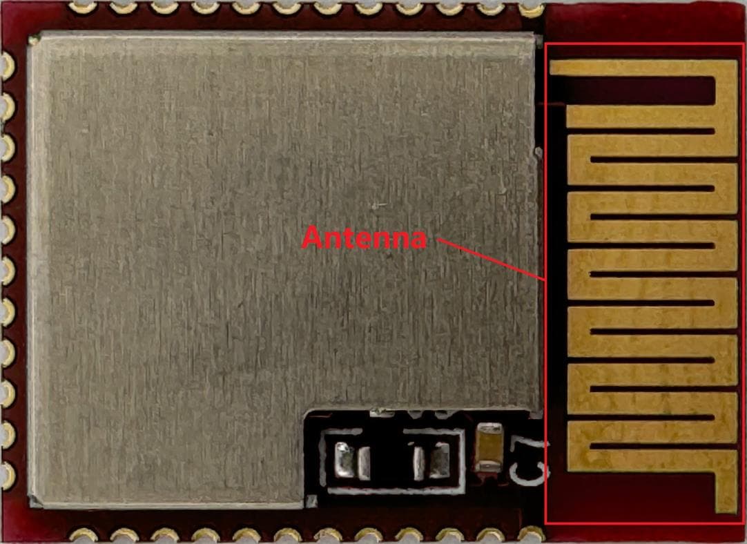
R7T2001102
Sep 04, 2024A Bluetooth module.
Equipment Class
DTS - Digital Transmission System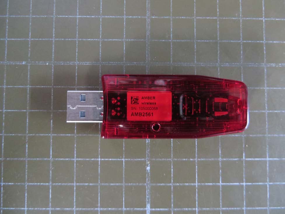
R7TAMB2561
Mar 19, 2015Low Power Transceiver
Equipment Class
DXT - Part 15 Low Power Transceiver, Rx Verified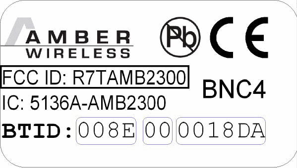
R7TAMB2300
Apr 10, 2007Bluetooth module BlueNiceCom IV
Equipment Class
DXX - Part 15 Low Power Communication Device Transmitter